Page 117 of 1002

Downloaded from www.Manualslib.com manuals search engine
- --
Cylinder Head Removal and Installation 1 --
< Remove complete air filter housing assembly with mass air
flow sensor:
Loosen
intalte duct hose clamp (A) at throttle assembly.
Loosen clamp and remove idle control line from intake duct
(B) and disconnect idle speed control valve electrical har-
ness connector.
Disconnect electrical harness connector
(C) from mass air
flow sensor.
Remove air filter housing mounting screw
(D).
Disconnect vent tube (E).
. Loosen air intalte duct clamp (F).
Carefully lifl air filter housing, mass air flow sensor, and in-
take duct hose out of engine bay.
4 Disconnect positive battery cable and remove intake rnani-
fold cover:
Remove protective cover from positive (+)jumper post.
Loosen and remove battery lead mounting nut (A).
Remove lead and push down through intake manifold.
* Remove trim covers (arrows) from fuel injector cover.
Remove cover hold down fasteners and lifl off cover.
4 Worlting above engine, disconnect the following:
Vent line from cylinder head cover. To remove, pinch clips
(arrows).
Electrical harness connector from VANOS solenoid valve
(A).
- Remove oxygen sensors and exhaust manifolds. See 180
Exhaust System.
CAUTION-
Remove oxygen sensors before removing exhaust mani-
fold to prevent damage.
Label oxygen sensor harness connectors so that they
can be reassembled correctly Do not interchange con-
nectors.
NOTE-
Front exhaust manifold must be removed before rear
manifold.
Page 118 of 1002

Downloaded from www.Manualslib.com manuals search engine
. .- -
Cylinder Head Removal and Installation
- Working at side of intake manifold near left strut tower, dis-
connect intake manifold resonance valve electrical harness
connector.
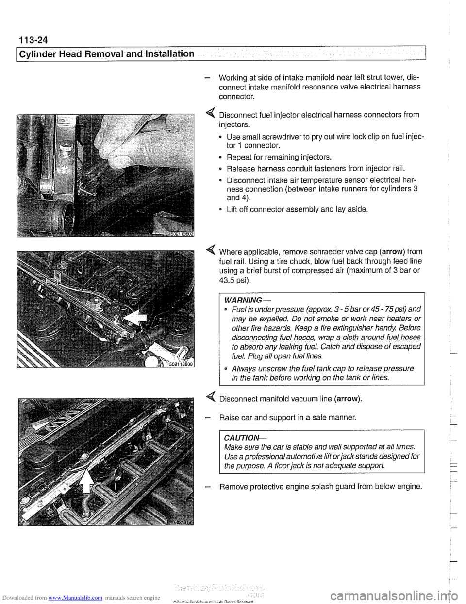
4 Disconnect fuel injector electrical harness connectors from
injectors.
- Use small screwdriver to pry out wire lock clip on fuel injec-
tor
1 connector.
Repeat for remaining injectors.
Release harness conduit fasteners from injector rail.
- Disconnect intake air temperature sensor electrical har-
ness connection (between intake runners for cylinders
3
and 4).
Lift off connector assembly and lay aside.
4 Where applicable, remove schraeder valve cap (arrow) from
fuel
ra~l. Using a tire chuck, blow fuel back through feed line
using a brief burst of compressed air (maximum of
3 bar or
43.5 psi).
WARNING-
Fuel is underpressure (approx. 3 - 5 bar or 45 - 75psi) and
may be expelled. Do not smoke or
work near heaters or
other fire hazards. Keep a fire extinguisher handy Before
d~sconnecting fuel hoses, wrap a cloth around fuel hoses
to absorb any leaking fuel. Catch and
dfspose of escaped
fuel. Plug all open fuel lines.
Always unscrew the fuel tank cap to release pressure
I in the tank before working on the tank or lines.
Disconnect manifold vacuum line (arrow)
Raise car and support in a safe manner,
CAUTION-
Make sure the car is stable and well supported at all times.
Use a professional automotive lift
orjack stands designed for
the purpose. A
floorjack is not adequate support.
Remove protective engine splash guard from below engine.
Page 123 of 1002

Downloaded from www.Manualslib.com manuals search engine
Cylinder Head Removal and Installation
4 If applicable, remove secondary air injection pump:
Disconnect hose at one-way valve
(A).
Remove bolts at support bracket on strut tower (arrows).
Disconnect electrical harness from bottom of secondary
air injection pump.
Remove mounting bracket from strut tower.
4 Remove ignition coils:
* Disconnect ignition coil harness connectors.
Remove coil mounting fasteners.
Remove coils.
* Remove ground straps.
CA UTIOI\C
Note location of all ground wires. Failure to reinstall grounds
can result in permanent damage to engine control module or
ignition system components.
Set coil harness to side of engine compartment
- Remove cylinder head cover mounting fasteners and remove
cylinder head cover.
NOTE-
The cylinder head cover mounting bolt insulators and gas-
ltets should be reinstalled in their original locations. Male
note of their arrangement during removal.
- Remove spark plugs
4 Remove oil baffle cover from above intake camshaft.
Page 124 of 1002

Downloaded from www.Manualslib.com manuals search engine
Cylinder Head Removal and installation - - .- - - - -
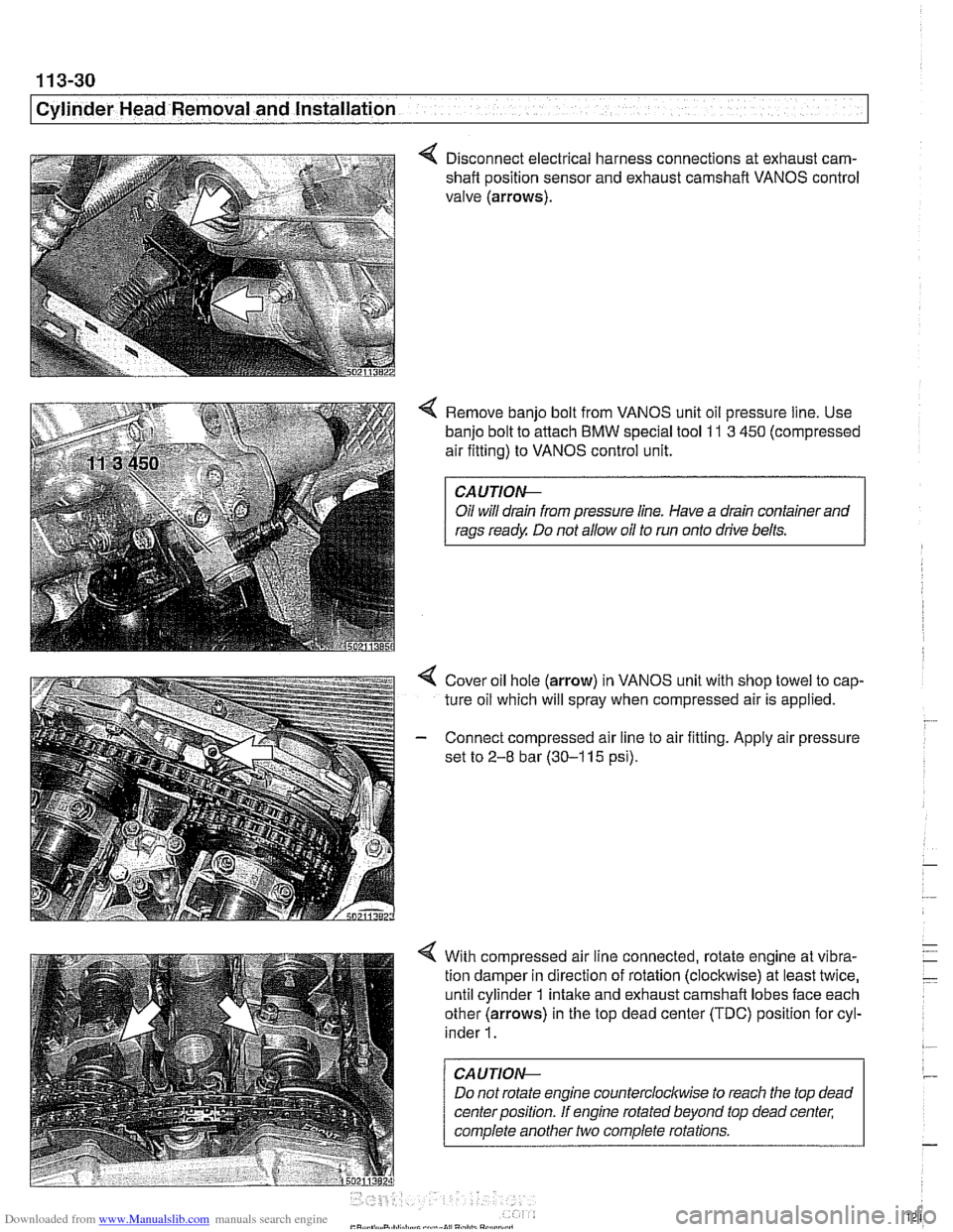
4 Disconnect electrical harness connections at exhaust cam-
shaft position sensor and exhaust camshaft VANOS control
valve (arrows).
4 Remove banjo bolt from VANOS unit oil pressure line. Use
banjo bolt to attach
BMW special tool 11 3 450 (compressed
air fitting) to VANOS control unit.
CAUTIOI\C
Oil will drain from pressure line. Have a drain container and
rags ready Do not allow oil to run onto drive belts.
4 Cover oil hole (arrow) in VANOS unit with shop towel to cap-
ture oil which will spray when compressed air is applied.
- Connect compressed air line to air fitting. Apply air pressure
set to
2-8 bar (30-1 15 psi).
4 With compressed air line connected, rotate engine at vibra-
tion damper in direction of rotation (clockwise) at least twice,
until cylinder 1 intake and exhaust camshaft lobes face each
other (arrows) in the top dead center (TDC) position for cyl-
inder
1.
CAUTION--
Do not rotate engine counterclocltwise to reach the top dead
center position. If engine rotated beyond top dead center;
complete another two complete rotations.
Page 149 of 1002

Downloaded from www.Manualslib.com manuals search engine
Cylinder Head Removal and Installation
- Install exhaust manifolds using new gaskets and nuts. Coat
manifold studs with copper paste prior to installing nuts.
Tightening torque Exhaust
maniiold to cylinder head (M7)
20 Nm (15 ft-lb)
- Install electrical harness connectors for oil pressure sender
and coolant temperature sensor before installing
intalte man-
ifold.
7 Install intake manifold:
1. Manifold mounting nuts: tighten to 15 Nm (1 1 ft-lb)
2. Fuel pipe bracltet
3. Fuel pipe bracltet
4. Vacuum pump bracltet
5. Manifold mounting bracltet
6.
Tank venting valve bracltet
7. Mounting bracket to manifold bolt (M6)
8. Mounting bracket to cylinder block nut (MIO), tighten to
47 Nm (33 fi-lb)
Intake manifold installation is reverse of removal, noting the
following:
* Use new fuel injector seals.
Carefully
check intake manifold gasket and replace if nec-
essary.
Inspect O-ring seal between mass air flow sensor and air
filter housing. To facilitate reassembly, coat seal with
acid-
free grease.
Use new fuel injector seals.
Carefully check intake manifold gasket and replace if
necessary.
CA UTIOPI-
When reattaching throttle assembly harness connector, con-
nector is fully tightened when arrows on connector
andplug
line up.
Tightening torque
lntalte manifold to cylinder
head (M7)
15 Nm (1 1 it-lb) ~ ~- Mounting bracket to cylinder bloclt (M10) 47 Nm (33 ft-lb)
Mounting bracket to intake manifold (MI?) 10 Nm (89 in-lb)
Page 150 of 1002

Downloaded from www.Manualslib.com manuals search engine
11 3-56
I Cvlinder Head Removal and Installation
- Installation of the remaining parts is reverse or removal, not-
ing the following:
- Refill cooling system as described in 170 Radiator and
Cooling System.
Change engine oil and filter as described in
020 Mainte-
nance.
If necessary, adjust accelerator cable.
a Reconnect battery.
CAUTION- To prevent damaging the engine electronic systems, installall
ground wire previously removed, including the ground wires
for the
ionition coils.
Tightening torque Coolant drain
pluq to cylinder bloclc 25 Nm (1 8 ft-lb)
Radiator cooling fan to coolant pump 40 Nm (30 ft-lb) -
Radiator drain screw to radiator 2.5
Nm (22 in-lb)
spark plug to cylinder head 25
Nm (1 8 ft-lb)
CYLINDER MEAD REMOVAL AND
INSTALLATION (M62 ENGINE)
This procedure covers cylinder head removal and installation
for the
M62 V-8 engine. Procedures forthe M62 TU VANOS
engine are not covered in this manual.
Intake manifold, left cylinder head, and right cylinder head re-
moval and installation are written as separate procedures.
The intake manifold must be removed before the cylinder
heads can be removed.
WARNING
-
Due to risk of personal injuv be sure the engine is cold be-
fore beginning the removal procedure.
Cylinder head removal and installation requires multiple spe-
cial service tools. Read the entire procedure before beginning
the repair.
Intake manifold, removal and installation,
M62 engine
- Disconnect negative (-) battery cable.
CAUTION- Prior to disconnecting the
batterj read the baitery discon-
nection cautions
in 001 General Cautions and Warnings.
Page 186 of 1002

Downloaded from www.Manualslib.com manuals search engine
Cylinder Head and Valvetrain
< Remove oil baffle cover from above intake camshaft(s)
- Rotate engine at crankshaft vibration damper center bolt in
normal direction of rotation (clockwise) until camshaft lobe of
lifter to be tested points away from the lifter, allowing valve to
be completely closed.
Use a plastic or wooden stick to press down on top of lifter
with approximately 3.5 Nm
(2.25 ft-ib) of force.
If the lifter collapses slightly as though spring loaded, air
may be trapped in the lifter.
NOTE-
Air trapped in hydraulic lifters may result from oil foaming (air
being drawn
in by the oil pump). This may be caused by a
faulty oil pump control valve O-ring; leaking oil pump pickup
gaslcet; or by oil starvation to pump.
Press down on top of lifter for
10 to 15 seconds uslng approx-
lmately 6 to 9 Nm (4.5 to 6.75 ft-lb) of force.
If anv clearance is created between the lifter and the
cam-
shafi lobe, the check valve in the lifter is not closing. Re-
place lifter.
- To replace a hydraulic lifter, remove appropriate camshaft.
Refer to camshaft removal procedures given in Camshaft
and lifter removal and installation.
Once camshaft is removed, withdraw faulty
lifter(s) and re-
place with new
lifter(s). Inspect lifter bores for wear and scor-
ing at arrows.
- Reinstall camshafts. See Camshaft and lifter removal and
installation.
Page 260 of 1002
Downloaded from www.Manualslib.com manuals search engine
1 17-24
I Camshaft Timing Chain
4 Remove banjo bolt from VANOS unit oil feed line and install
BMW special tool 11 3 450.
NOTE-
Oil will drain from oil feed line.
- Connect compressed air line (with pressure set to 2-8 bar or
30-1 10 psi.) to air fitting.
4 Measure gap (A) between secondary timing chain tensioner
and
intake camshaft sensor wheel. Make note of distance.
4 Connect cable test (BMW special tool 11 6 410) to VANOS
connector. Connect positive clip to positive battery terminal.
- Connect negative clip to battery negative terminal.
CAUTION-
Reversing terminals on special tool will damage diode on
VANOS solenoid valve.