2000 BMW 528i General wiring
[x] Cancel search: General wiringPage 387 of 1002

Downloaded from www.Manualslib.com manuals search engine
Battery, Starter, ~lternatorl
- Disconnect wiring from starter.
4 Note routing for cables. Routing varies depending on model
and transmission. When reinstalling, make sure cables do
not chafe.
- Using a long extension and universal joint from output end of
transmission, remove bolts fastening starter to transmission
bell housing and engine block.
- Remove starter from below
4 Checlc starter pinion gear and flywheel teeth for damage.
- Installation is reverse of removal.
Tightening torques
Starter to engine 47 Nrn (35 It-lb)
Starter sipport bracket to starter 5 Nrn (44 in-lb)
Starter support
bracket to engine 47 Nrn (35 ft-lb)
Wlre terminals to slarter
M5 5 Nrn (44 in-lb)
M6 7 Nrn (62 in-lb)
M8 13 Nrn (10 ft-lb)
Starter, removing and installing
(V-8 engine)
The starter is on the right (passenger) side of the engine, and
is removed from below. Access to starter bolts is difficult. Be
sure to have the proper tools on hand before proceeding.
- Disconnect negative (-) battery cable
CA UTIOW-
Prior to disconnecting the battery, read the battev discon-
nection cautions in
OOlGeneral Cautions and Warnings. -
- Raise vehicle and support safely.
/ WARNING- 1 ~ ~~ ~~ ~~~ ~
Make sure the car is stable and well supported at all times.
Use a professional automotive lift orjacltstands designed for
I the purpose. A floor jack is not adequate support I
Page 395 of 1002

Downloaded from www.Manualslib.com manuals search engine
Fuel Injection
Warnings and cautions
For personal safety, as well as the protection of sensitive
electronic components, adhere to the warnings and cautions
on the following pages.
WARNING-
Gasoline is highly flammable and its vapors are explosive.
Do not smoke or work on a car near heaters or other fire
hazards when diagnosing and repairing fuel system prob-
lems. Have a fire extinguisher available in case of an emer-
gency
Renew fuel system hoses, clamps and O-rings any
time they are removed.
When working on an open fuel system, wear suitable
hand protection, as prolonged contact
with fuel can
cause illnesses and skin disorders.
* The ignition system produces high voltages that can be
fatal. Avoid contact with exposed terminals. Use ex-
treme caution when
working on a car with the ignition
switched on or the engine running.
CAUTION-
- Disconnecting the battery may erase fault code($ storedin
memory Check for fault codes prior to disconnecting the
battery cables. Read the battery disconnection cautions in
001 General Warnings and Cautions.
a Connect and disconnect the DME system wiring and
1 test equipment leads only when the ignition is switched
off.
Wait at least 1 minute after turning off the ignition be-
fore removing the engine control module (ECM) con-
nector. If the connector is removed before this time,
residualpower in the system relay may damage the
control module.
Fuel system cleaners and other chemical additives oth-
er than those specifically recommended by BMW may
damage the catalytic converter, the oxygen sensor or
other fuel supply components.
* Do not connect any test equipment that delivers a 12-
volt power supply to terminal 15 (+) of the ignition coil.
The current flow may damage the ECM. In general,
connect test equipment only as specified by BMW or
the equipment maker.
Only use a digital
multirneter for electrical tests. Only
use an LED test light for
quiclc tests.
Page 405 of 1002

Downloaded from www.Manualslib.com manuals search engine
Fuel injectors, checking and replacing
The fuel injectors are electronically controlled solenoid valves
that provide precisely metered and atomized fuel into the en-
gine intake ports.
The injectors receive voltage from the ECM relay. The ECM
controls the opening by activating the ground circuit
forthe in-
jector valve solenoids. The ECM varies the duration (in milli-
seconds) of "opening" time to regulate the
airlfuel ratio.
For a quick
check of the injectors, run the engine and touch
each injector with a screwdriver or stethoscope. You should
feel a vibration or hear a buzzing
Remove fuel injection harness from injectors by unclipping
locking clip at each injector. Lift harness off injectors.
CA U JIOG
Be sure ignition is OFF before disconnecting or reconnecting
DME system components.
Use a multimeter to test injector coil resistance between in-
jector terminals.
l~uel injector coil resistance 16R at 20" C (68" F)
Disconnect negative
(-) battery cable
CAUTIOG
Prior to disconnecting the battery, read the battery discon-
nection cautionsgiven
in 001 General Warnings and Cau-
tions.
4 Remove plastic trim plugs (arrows) and fasteners, then re.
move cover from above fuel injectors.
- Disconnect vacuum line from fuel pressure regulator.
- Remove wiring harness duct mounting fasteners.
Page 669 of 1002

Downloaded from www.Manualslib.com manuals search engine
Steering and Wheel ~li~nrnentl
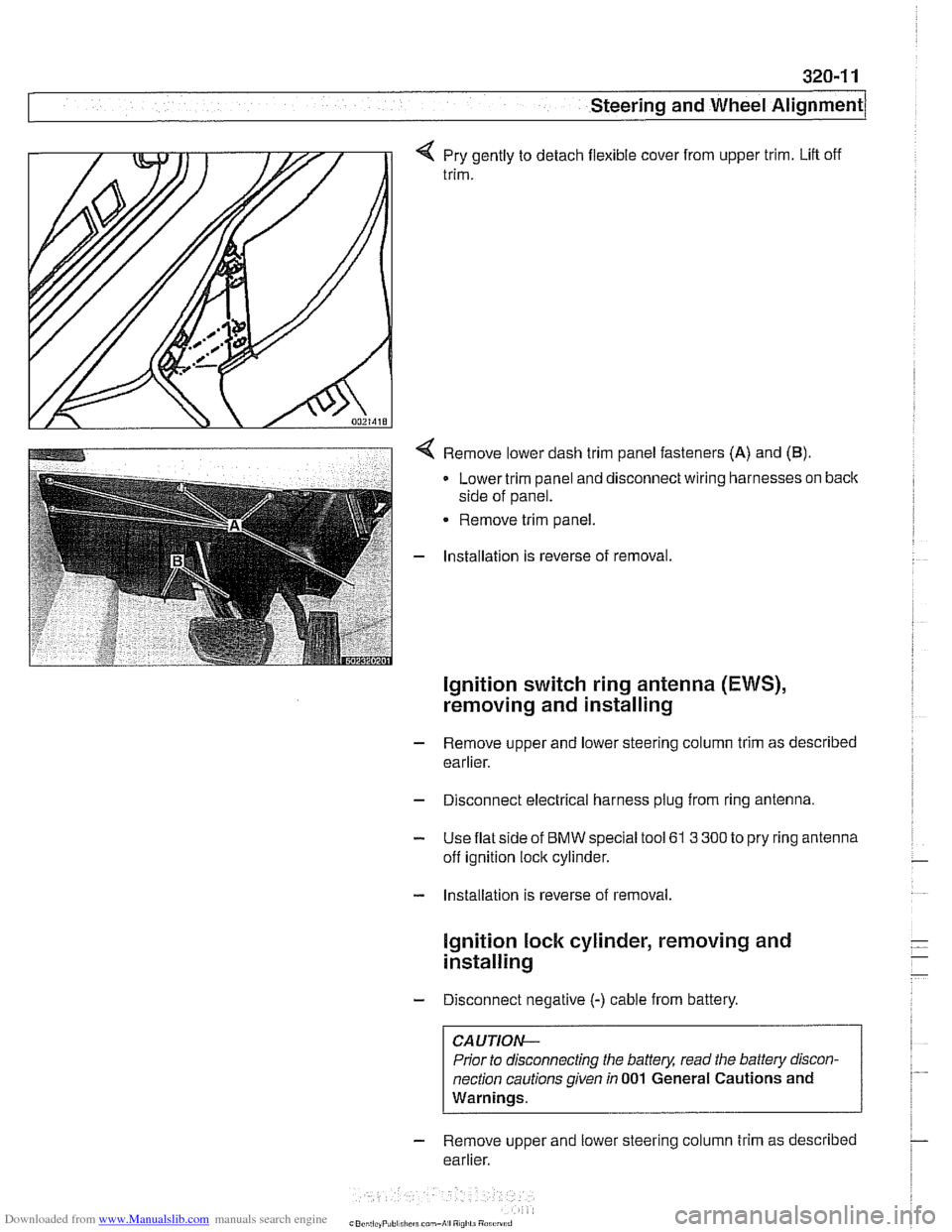
q Pry gently to detach flexible cover from upper trim. Lift off
trim.
< Remove lower dash trim panel fasteners (A) and (B).
Lower trim panel and disconnect wiring harnesses on back
side of panel.
Remove trim panel.
- Installation is reverse of removal.
Ignition switch ring antenna (EWS),
removing and installing
- Remove upper and lower steering column trim as described
earlier.
- Disconnect electrical harness plug from ring antenna.
- Use flat side of BMW special tool 61 3 300 to pry ring antenna
off ignition lock cylinder.
- Installation is reverse of removal.
lgnition lock cylinder, removing and
installing
- Disconnect negative (-) cable from battery.
CAUTION-
Prior to disconnecting the battery, read the battery discon-
nection cautions given
in 001 General Cautions and
Warnings.
- Remove upper and lower steering column trim as described
earlier.
Page 776 of 1002

Downloaded from www.Manualslib.com manuals search engine
340-1 4
Brakes
4 Apply a thin coating of BMW anti-squeal compound to caliper
contact face
(arrow).
Do not apply grease to brake pad backing plate.
Right Left
CAUTION-
Do not let calliper rubber dust sleeve come in contact with
anti-squeal compound. The rubber will swell and deteriorate.
4 Apply a thin coating of BMW anti-squeal compound to bralte
pad rests (arrows) on pad carrier.
4 When installing directional brake pads, install the marked
pads as shown.
NOTE-
BMW-supplied (OEM) front brake pads may be marked as di-
rectionalpads. Aftermarket brands are generally not labeled
as directional. When installing directional pads, be sure to in-
stall them as indicated in the illustration.
- Where applicable, insert brake pad wear sensor into cutout
in new pad. Push sensor into pad cutout until it locks into
place.
- -
- NOTE-
If brake lining indicator light illuminatedprior to brake pad re-
placement, replace wear sensor.
- Route pad wear sensor wiring through caliper opening and
under bleeder dust cap.
Page 825 of 1002

Downloaded from www.Manualslib.com manuals search engine
WARNING -
E39 cars are fitted with side-impact airbags in the front doors
and optional side impact
airbags in the rear doors. When
servicing doors, always disconnect the negative
(-) battery
terminal. See
721 Airbag System (SRS) for cautions and
procedures relating to the
airbag system.
Door trim panel, removing and installing
Disconnect negative (-) battery cable.
CAUTION--
Prior to disconnecting the battem read the batfew discon-
nection cautions given in
001 General Cautions and warn-
ings.
Q Open door, and remove screw (arrow) located
in air
duct.
< Pry out seat memory switch and disconnect wiring harness.
Page 896 of 1002

Downloaded from www.Manualslib.com manuals search engine
51 5-2
/Central Locking and Anti-Theft
This section covers repair information for door, trunk and car-
go compartment locks, central locking, electronic
immob~liza-
tion (EWS) and anti-theft alarm (DWA).
€39 cars are equipped with sophisticated self-diagnostic elec-
trical systems. When experiencing malfunctions relating to
central locking. EWS or anti-theft systems, start the diagnosis
process using the
BMW service tester DIS, GT 1, MoDiC or
equivalent scan tool. An advanced diagnostic scan tool can
usually pinpoint electrical faults quickly and safely.
Additional electrical information can be found in:
610 Electrical Component Locations
ELE Electrical Wiring Diagrams
Central locking in E39 vehicles controls the door
locks, trunk
or tailgate lock and fuel filler flap lock. The control module for
the Central Body Electronics system (ZKE
Ill), lknown as the
General Module (GM
Ill), controls central locking.
ZKE
Ill manages the following central locking related func-
tions:
Central locking
* Keyless entry
Key memory
Power trunk release
Electric opening of tailgate
DWA alarm system
Diagnosis
General Module
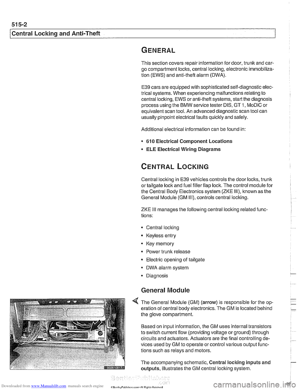
4 The General Module (GM) (arrow) is responsible for the op-
eration of central body electronics. The GM is located behind
the glove compartment.
Based on input information, the GM uses internal transistors
to switch current flow (providing voltage or ground) through
circuits and actuators. Actuators are the final controlling de-
vices used by GM to operate or control various output func-
tions such as relays and motors.
The accompanying schematic, Central locking inputs and
outputs, illustrates the GM central locking system.
Page 958 of 1002

Downloaded from www.Manualslib.com manuals search engine
721 -1 0
/Airbag System (SRS)
4 Pry up cover from top of passenger side airbag on dash-
board.
4 Remove airbag mounting bolts (arrows)
- Lift airbag and disconnect electrical harness connector. Re-
move
airbag.
WARNING-
Store the removed airbag unit with the soft pad facing up. If
stored facing down, accidental deployment could propel it vi-
olentlv into the
ail: causino inium
- Installation is reverse of removal. Make sure wiring harness
is not pinched when installing
airbag unit in dashboard.
Tightening torques
-
Passenger alr bag to 10 NM (88 in-lb)
dashboard (Me)
Door mounted side-impact airbag,
removing and installing
- Disconnect negatlve (-) cable from battery and cover nega-
tive terminal with insulating material.
CAUTION-
Prior to disconnecting the battea read the battery discon-
nection cautions given
in 001 General Warnings and Cau-
tions.
- Remove inside door panel as described in 41 1 Doors