Page 49 of 1002
Downloaded from www.Manualslib.com manuals search engine
< 6-cylinder engine with hydraulic belt tensioners.
Use long-handled wrench to turn
A/C belt tensioner (A)
clockwise. Remove AfC belt.
* Similarly, turn main engine drive belt tensioner (B)
clockwise and remove belt.
< Some models have a dust cover over belt tensioner release
lug, which must be pried off prior to removing belt.
4 6-cylinder engine with spring-loaded belt tensioners.
Use long-handled wrench to turn
AfC belt tensioner
release lug
(A) clocltwise (against spring tension).
Remove
AfC belt.
Similarly, turn main engine drive belt tensioner lug
(B)
clocltwise and remove belt.
Page 51 of 1002
Downloaded from www.Manualslib.com manuals search engine
Maintenance
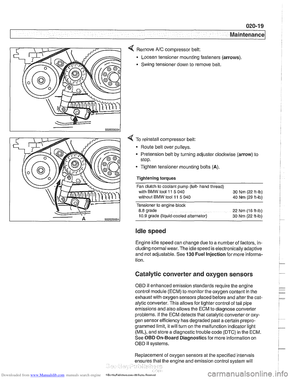
< Remove NC compressor belt:
Loosen tensioner mounting fasteners (arrows)
Swing tensioner down to remove belt.
4 To reinstall compressor belt:
Route belt over pulleys.
* Pretension belt by turning adjuster clockwise (arrow) to
stop.
- Tighten tensioner mounting bolts (A).
Tightening torques
Fan clutch to coolant pump (left- hand thread)
with BMW tool
11 5 040
30 Nm (22 ft-lb)
without BMW tool 11 5 040
40 Nm (29 ft-lb)
Tensioner to engine block
8.8 grade
22 Nm (16 ft-lb)
10.9 grade (Ilquid-cooled alternator) 30 Nm (22 ft-lb)
Idle speed
Engine idle speed can change due to a number of factors, in-
cluding normal wear. The idle speed is electronically adaptive
and not adjustable. See
130 Fuel Injection for more informa-
tion.
Catalytic converter and oxygen sensors
OBD II enhanced emission standards require the engine
control module (ECM) to monitor the oxygen content in the
exhaust with oxygen sensors placed before and after the cat-
alytic converter. This allows for tighter control of tail pipe
emissions and also allows the ECM to diagnose converter
problems. If the ECM detects that catalytic converter or oxy-
gen sensor efficiency has degraded past a certain
prepro-
grammed limit, it will turn on the malfunction indicator light
(MIL), and store a diagnostic trouble code (DTC) in the ECM.
See OBD On-Board Diagnostics for more information on
OBD
ll systems.
Replacement of oxygen sensors at the specified intervals
he engine and emission control system will
Page 80 of 1002
Downloaded from www.Manualslib.com manuals search engine
110-8
1 Engine Removal and Installation
4 M52 TU, M54 engine: Remove fasteners (arrows) retaining
wiring harness conduit to throttle body.
4 M52 TU, M54 engine: Working at throttle housing, rotate har-
ness plug (arrow) counterclockwise and remove.
4 M52 TU, M54 engine: Disconnect electrical harness connec-
tor at idle speed control valve (arrow), directly above throttle
valve.
Page 92 of 1002
Downloaded from www.Manualslib.com manuals search engine
11 0-20
Engine Removal and Installation
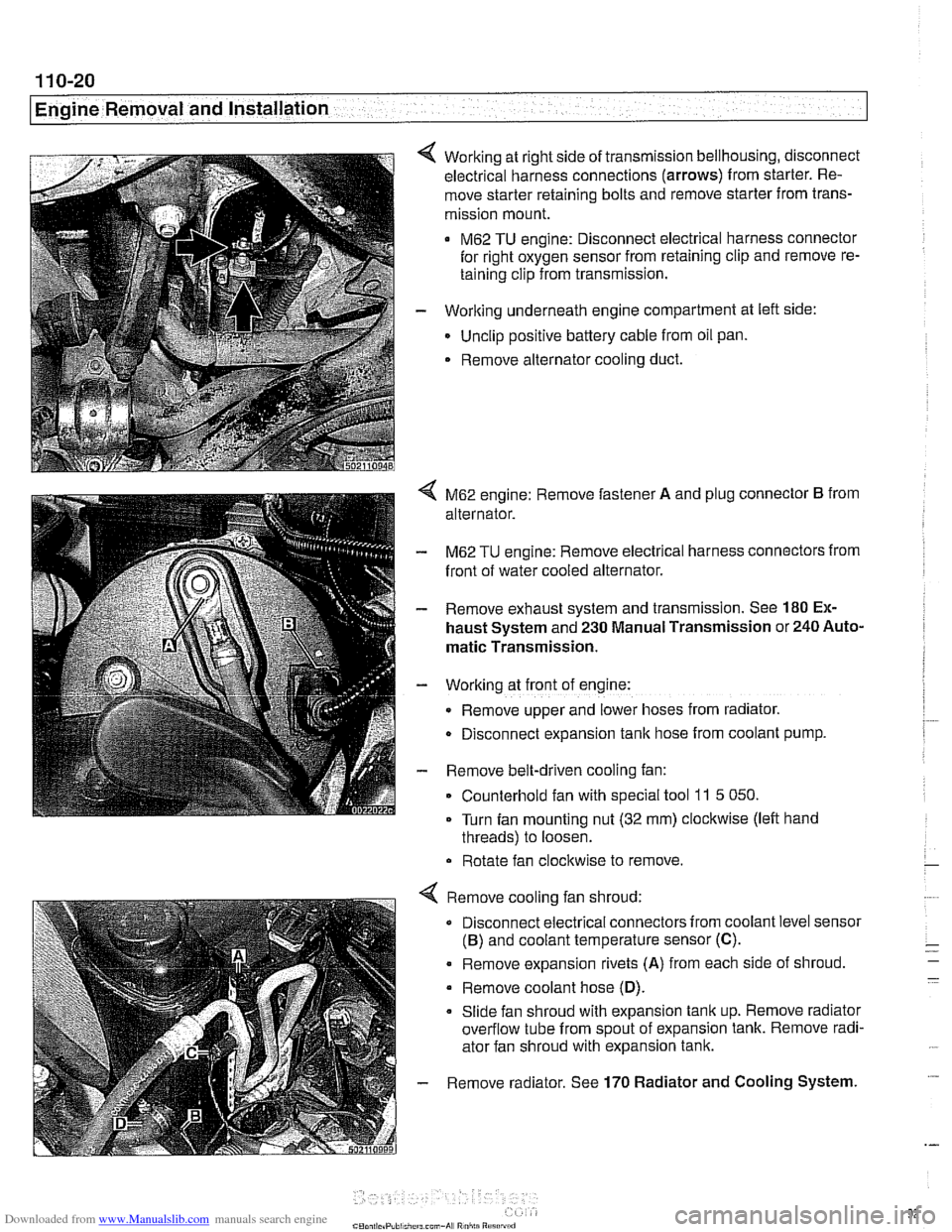
Working at right side of transmission bellhousing, disconnect
electrical harness connections (arrows) from starter. Re-
move starter retaining bolts and remove starter from trans-
mission mount.
M62 TU engine: Disconnect electrical harness connector
for right oxygen sensor from retaining clip and remove re-
taining clip from transmission.
- Working underneath engine compartment at left side:
Unclip positive battery cable from oil pan.
. Remove alternator cooling duct.
4 M62 engine: Remove fastener A and plug connector B from
alternator.
- M62 TU engine: Remove electrical harness connectors from
front of water cooled alternator.
- Remove exhaust system and transmission. See 180 Ex-
haust System and 230 Manual Transmission or 240 Auto-
matic Transmission.
- Working at front of engine:
Remove upper and lower hoses from radiator.
D~sconnect expansion tank hose from coolant pump.
- Remove belt-driven cooling fan:
Counterhold fan with special tool
11 5 050.
Turn fan mounting nut (32 mm) clockwise (left hand
threads) to loosen.
Rotate fan clockwise to remove.
Remove cooling fan shroud:
Disconnect electrical connectors from coolant level sensor
(B) and coolant temperature sensor (C).
. Remove expansion rivets (A) from each side of shroud
Remove coolant hose
(D).
Slide fan shroud with expansion tank up. Remove radiator
overflow tube from spout of expansion tank. Remove radi-
ator fan shroud with expansion tank.
Remove radiator. See
170 Radiator and Cooling System.
Page 103 of 1002
Downloaded from www.Manualslib.com manuals search engine
11 3-9
Cylinder Head Removal and Installation
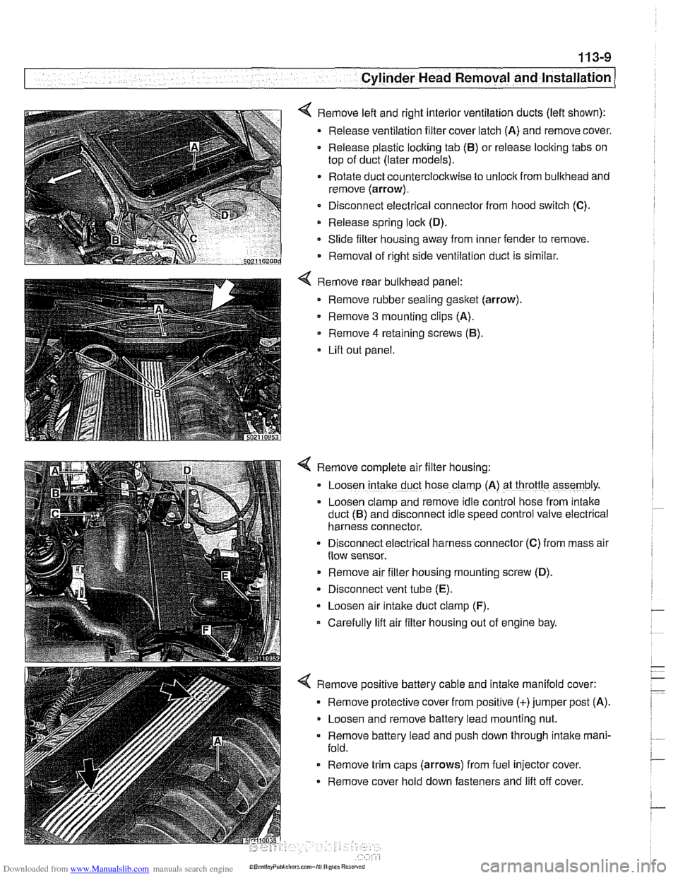
< Remove left and right interior ventilation ducts (left shown):
Release ventilation filter cover latch (A) and remove cover.
Release plastic locking tab
(6) or release locking tabs on
top of duct (later models).
Rotate duct counterclockwise to unlock from bulkhead and
remove (arrow).
Disconnect electrical connector from hood switch
(C).
Release spring lock (D).
Slide filter housing away from inner fender to remove.
Removal of right side ventilation duct is similar.
Remove rear bulkhead panel: Remove rubber sealing
gasket (arrow).
0 Remove 3 mounting clips (A).
Remove
4 retaining screws (6).
Lift out panel.
< Remove complete air filter housing:
Loosen
intake duct hose clamp (A) at throttle assembly.
Loosen clamp and remove idle control hose from
~ntake
duct (6) and disconnect Idle speed control valve electr~cal
harness connector.
Disconnect
electr~cal harness connector (C) from mass alr
flow sensor.
Remove air filter housing mounting screw (D).
Disconnect vent tube
(E).
Loosen air intake duct clamp (F).
Carefully lift air filter housing out of engine bay.
4 Remove positive battery cable and intake manifold cover:
Remove protective cover from positive (+)jumper post (A).
Loosen and remove battery lead mounting nut.
Remove battery lead and push down through intake mani-
fold.
Remove trim caps (arrows) from fuel injector cover.
Remove cover hold down fasteners and lift off cover.
Page 124 of 1002
Downloaded from www.Manualslib.com manuals search engine
Cylinder Head Removal and installation - - .- - - - -
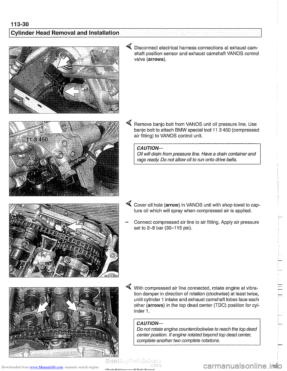
4 Disconnect electrical harness connections at exhaust cam-
shaft position sensor and exhaust camshaft VANOS control
valve (arrows).
4 Remove banjo bolt from VANOS unit oil pressure line. Use
banjo bolt to attach
BMW special tool 11 3 450 (compressed
air fitting) to VANOS control unit.
CAUTIOI\C
Oil will drain from pressure line. Have a drain container and
rags ready Do not allow oil to run onto drive belts.
4 Cover oil hole (arrow) in VANOS unit with shop towel to cap-
ture oil which will spray when compressed air is applied.
- Connect compressed air line to air fitting. Apply air pressure
set to
2-8 bar (30-1 15 psi).
4 With compressed air line connected, rotate engine at vibra-
tion damper in direction of rotation (clockwise) at least twice,
until cylinder 1 intake and exhaust camshaft lobes face each
other (arrows) in the top dead center (TDC) position for cyl-
inder
1.
CAUTION--
Do not rotate engine counterclocltwise to reach the top dead
center position. If engine rotated beyond top dead center;
complete another two complete rotations.
Page 139 of 1002
Downloaded from www.Manualslib.com manuals search engine
Cylinder Head Removal and Installation
4 While maintaining tension on timing chain, rotate crankshaft
at vibration damper from
30" before TDC in direction of rota-
tion (clockwise) until number
1 cylinder is at TDC position
with line between the
OIT (arrow) on front pulley lined up
with boss on lower timing chain cover.
Page 147 of 1002
Downloaded from www.Manualslib.com manuals search engine
Cylinder Head Removal and Installation /
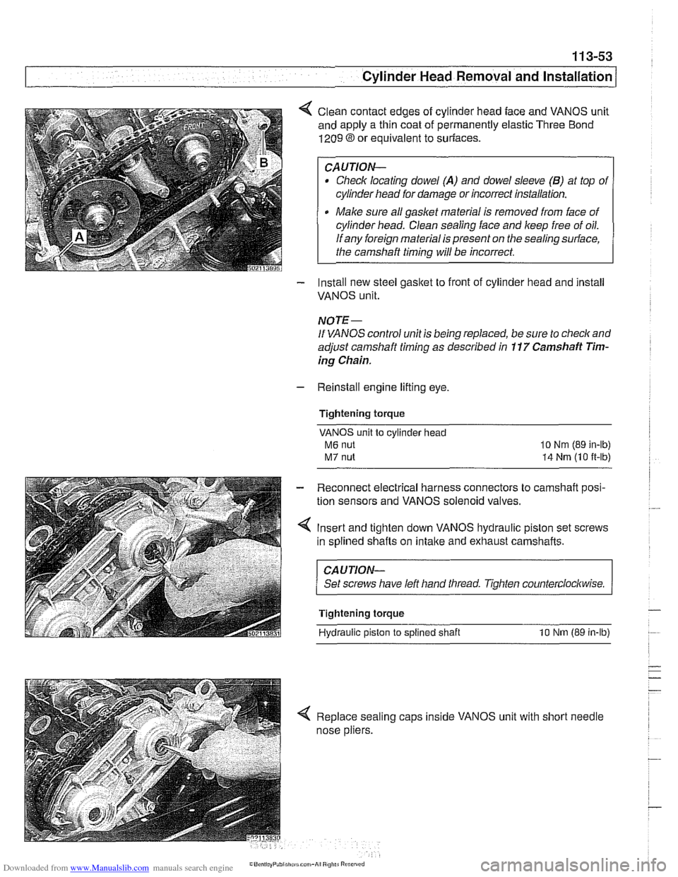
< Clean contact edges of cylinder head face and VANOS unit
and apply a thin coat of permanently elastic Three Bond
1209 8 or equivalent to suriaces.
CAUTION-
Check locating dowel (A) and dowel sleeve (B) at top of
cylinder head for damage or incorrect installation.
Make sure all gasket material is removed from face of
cylinder head. Clean sealing face and keep free of oil.
If any foreign material is present on the sealing surface,
the camshaft timing will be incorrect.
- Install new steel gasket to front of cylinder head and install
VANOS unit.
NOTE -
If VANOS control unit is being replaced, be sure to check and
adjust camshaft timing as described in
11 7 Camshaft Tim-
ing Chain.
- Reinstall engine lifting eye.
Tightening torque
VANOS unit to cylinder head
M6 nut
M7 nut
lo Nm (89 in-lb)
14 Nrn (10 it-lb)
- Reconnect electrical harness connectors to camshaft posi-
tion sensors and VANOS solenoid valves.
4 Insert and tighten down VANOS hydraulic piston set screws
in splined shafts on
intake and exhaust camshafts.
CAUJION-
Set screws have left hand tliread. Tighten counterclockwise.
Tightening torque
Hydraulic piston
to splined shaft 10 Nm (89 in-lb)
< Replace sealing caps inside VANOS unit with short needle
nose pliers.