Page 21 of 71
Servicing clutch release mechanism Servicing clutch release mechanism 1.Gearbox 2.Ball stud
◆ Tighten to 25
Nm
◆ Lubricate with MoS2-grease 3.Intermediate piece 4.Dished washer
◆ Smaller
diameter
(convex side)
to guide
sleeve
5.O-ring
◆ Replacing
6.Replace input shaft sealing ring
◆ is available
as a
replacement
part together with the guide sleeve -Item
7-
◆ Pack space
between
sealing and
dust lips half-
full with
sealing grease G 052 128 A1.
7.Guide sleeve ◆ Is available as
a replacement
part together
with the
sealing ring -
Item 6-
◆ Installation
position: The
oil drain bore
points
downwards.
◆ Before removing/fitting in order to
protect the
sealing ring -
Item 6- pull
shrink-fit hose
over the
splines on the
input shaft
8.Retaining spring Page 1 of 65-Speed Manual Gearbox 01A 4WD4.3.2014vw-wi://rl/A.en-GB.4B-S-S01AA.wi::21141314.xml?xsl=2
Page 28 of 71

plates) the hub splines.
Remove corrosion
and apply only a very thin coating of grease G 000 100 to the
splines. Then move clutch plate to and for on input shaft until
hub moves freely on
shaft. Excess grease
must be removed.
◆ Pressure plates are
protected against
corrosion and
greased. Only the
contact surface may be cleaned, otherwise the service life of the
clutch will be
considerably
reduced.
◆ Tighten securing
bolts in small steps in
diagonal sequence to
avoid damaging
centring holes in
pressure plate and
centring pins on
flywheel.
‒ Remove the gearbox
to work on the
clutch=>Page 34-35.
1.Flywheel/dual mass
flywheel
◆ Ensure that
centring pins
are a tight fit.
◆ Contact
surface for
clutch lining must be free of grooves, oil
and grease
◆ Observe
removal
instructions for
the weight-
optimised dual-
mass flywheel
=>Fig.2
◆ Removing and
installing:
=> Relevant
engine
workshop
manual,
Mechanical
components;
Repair group
13 Page 2 of 75-Speed Manual Gearbox 01A 4WD4.3.2014vw-wi://rl/A.en-GB.4B-S-S01AA.wi::21141315.xml?xsl=2
Page 29 of 71
2.Bolt for flywheel ◆ Always replace ◆ Vehicles
without dual
mass flywheel
60 Nm + turn
90° further
◆ With dual-
mass flywheel ‒ Screw length
22.5 mm
60 Nm + turn
90° further
‒ Screw length
43 mm
60 Nm + turn
180° further
3.Detach clutch plate
◆ Installation
position:
‒ Spring pack
(coil springs)
towards thrust
and gearbox
‒ Clutch lining
must make full Page 3 of 75-Speed Manual Gearbox 01A 4WD4.3.2014vw-wi://rl/A.en-GB.4B-S-S01AA.wi::21141315.xml?xsl=2
Page 31 of 71
installing:
=> Relevant
engine
workshop
manual,
Mechanical
components;
Repair group
13 → Fig.1 Centring clutch plate and removing and installing thrust plate
‒ Loosen and tighten bolts gradually in
several stages working diagonally.
Tightening torque: 25 Nm.
‒ Reverse position of retainer 3067 when
removing.
‒ Installation position of clutch plate: spring
pack (coil springs) or marking
"Getriebeseite" towards pressure plate and
gearbox.
‒ Clutch lining and contact surface of
pressure plate must make full contact with
flywheel before securing bolts are inserted. ‒ Use mandrel 3176 to centre clutch plate.
→ Fig.2 Weight-optimised dual-mass flywheel
Identification: Cheese-head bolts -B- are
countersunk in the flywheel -A-. Page 5 of 75-Speed Manual Gearbox 01A 4WD4.3.2014vw-wi://rl/A.en-GB.4B-S-S01AA.wi::21141315.xml?xsl=2
Page 42 of 71

‒ Install lower engine/gearbox securing bolts and bolts for starter. For this
purpose, insert the starter.
=> Electrical System; Repair group 27; Removing and installing starter
‒ Bolt drive shafts to flange shafts.
=> Running Gear, FWD and 4WD; Repair group 40
‒ The threaded bores in the flange
shaft of the manual gearbox for the
propshaft must be cleaned of
remaining locking fluid with a thread
tap before assembling
‒ Replace front gaskets at propshaft
=> Page 39-79 and at drive shafts.
‒ Attaching propshaft => Page 39-84.
‒ Check selector rod and push rod,
adjust if necessary => Page 34-11.
‒ Tension free alignment of exhaust
system
=> 4-cylinder Engine (5-valve turbo), Mechanical Components; Repair group 26; Removing and installing parts of exhaust system; Stress-free alignment of exhaust system
=> 6-cylinder Engine (5-valve), Mechanical Components; Repair group 26; Removing and installing parts of exhaust system; Stress-free alignment of exhaust system
‒ Check oil level in manual gearbox => Page 34-56.
‒ Electrical connections and routing:
=> Current Flow Diagrams, Electrical Fault-
finding and Fitting Locations binder
‒ Connect the battery.
Notes:
◆ If the battery is reconnected, please
ensure that the vehicle equipment
(radio, radio/navigation system,
clock, electric window lifters) is
activated as described in the
operating instructions.
◆ Deactivate the service mode of the
telematics control unit.
=> Radio, Telephone and Navigation Page 2 of 45-Speed Manual Gearbox 01A 4WD4.3.2014vw-wi://rl/A.en-GB.4B-S-S01AA.wi::21141329.xml?xsl=2
Page 46 of 71

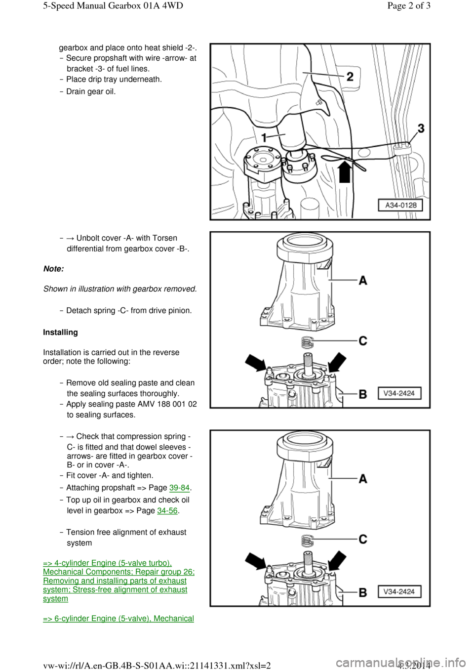
gearbox and place onto heat shield -2-. ‒ Secure propshaft with wire -arrow- at bracket -3- of fuel lines.
‒ Place drip tray underneath.
‒ Drain gear oil. ‒ → Unbolt cover -A- with Torsen
differential from gearbox cover -B-.
Note:
Shown in illustration with gearbox removed. ‒ Detach spring -C- from drive pinion.
Installing
Installation is carried out in the reverse
order; note the following:
‒ Remove old sealing paste and clean
the sealing surfaces thoroughly.
‒ Apply sealing paste AMV 188 001 02 to sealing surfaces. ‒ → Check that compression spring -
C- is fitted and that dowel sleeves -
arrows- are fitted in gearbox cover -
B- or in cover -A-.
‒ Fit cover -A- and tighten.
‒ Attaching propshaft => Page 39-84.
‒ Top up oil in gearbox and check oil
level in gearbox => Page 34-56.
‒ Tension free alignment of exhaust
system
=> 4-cylinder Engine (5-valve turbo), Mechanical Components; Repair group 26; Removing and installing parts of exhaust system; Stress-free alignment of exhaust system
=> 6-cylinder Engine (5-valve), Mechanical Page 2 of 35-Speed Manual Gearbox 01A 4WD4.3.2014vw-wi://rl/A.en-GB.4B-S-S01AA.wi::21141331.xml?xsl=2
Page 58 of 71
◆ V.A.G 1331 Torque wrench
◆ Sealant AMV 188 001 02 Notes:
◆ It is not necessary to remove the
differential to remove the above-
mentioned components => Page 34-74.
◆ Removal is only necessary when
adjustments have to be carried out
=> adjustment overview, Page 39-45.
Removing
‒ Place drip tray V.A.G 1306
underneath the gearbox.
‒ Drain gearbox oil using socket
attachment 3357.
‒ → Secure gearbox in assembly
stand VW 540. Page 2 of 115-Speed Manual Gearbox 01A 4WD4.3.2014vw-wi://rl/A.en-GB.4B-S-S01AA.wi::21141337.xml?xsl=2
Page 59 of 71
‒ → Detach clutch release lever -A-
with release bearing.
Notes:
◆ Before pulling off guide sleeve, cover input shaft splines with a shrink-fit
hose to protect oil seal.
◆ Removing oil seal from guide sleeve
=> Page 30-32.
‒ Unscrew guide sleeve -B-.
‒ Remove dished washer -C-.
‒ Remove circlip -D- in front of input
shaft ball bearing. ‒ If the ball bearing, input shaft or
gearbox housing is not to be
replaced, note the thickness of the
circlip.
‒ → Pull the input shaft ball bearing
out of the gearbox housing. Page 3 of 115-Speed Manual Gearbox 01A 4WD4.3.2014vw-wi://rl/A.en-GB.4B-S-S01AA.wi::21141337.xml?xsl=2