Page 16 of 44
01-119
DTC
VAG 1551 scan tool
display Possible cause
Corrective action
01382
Alarm Via ATW Sensor
fl
Break in attempt at left-front side window or after a
function test
False alarm- Erase DTC memory.
- Perform function test page 01
-
128
.
- Adapt sensitivity of sensors page 01
-135
.
01383
Alarm Via ATW Sensor
fr
Break in attempt at right-front side window or after a
function test
False alarm- Erase DTC memory.
- Perform function test page 01
-
128
.
- Adapt sensitivity of sensors page 01
-135
.
Pa
ge 16 of 44 Ultrasonic interior monitorin
g On Board Dia
gnostic
(OBD
)
11/20/2002 htt
p://127.0.0.1:8080/audi/servlet/Dis
play?action=Goto&t
yp
e=re
pair&id=AUDI.B5.BD04.01.4
Page 17 of 44

01-120
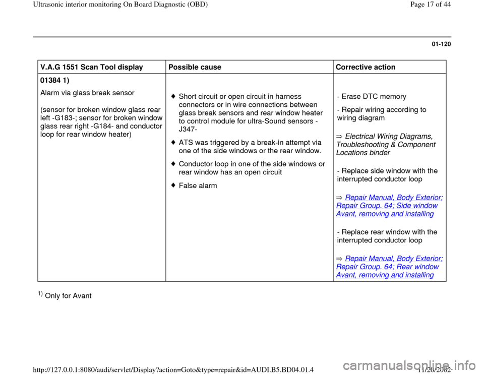
V.A.G 1551 Scan Tool display
Possible cause
Corrective action
01384 1)
Alarm via glass break sensor
(sensor for broken window glass rear
left -G183-; sensor for broken window
glass rear right -G184- and conductor
loop for rear window heater)
Short circuit or open circuit in harness
connectors or in wire connections between
glass break sensors and rear window heater
to control module for ultra-Sound sensors -
J347- ATS was triggered by a break-in attempt via
one of the side windows or the rear window. Conductor loop in one of the side windows or
rear window has an open circuit False alarm Electrical Wiring Diagrams,
Troubleshooting & Component
Locations binder
Repair Manual, Body Exterior;
Repair Group. 64; Side window Avant, removing and installing
Repair Manual, Body Exterior;
Repair Group. 64; Rear window Avant, removing and installing
- Erase DTC memory
- Repair wiring according to
wiring diagram
- Replace side window with the
interrupted conductor loop - Replace rear window with the
interrupted conductor loop
1) Only for Avant
Pa
ge 17 of 44 Ultrasonic interior monitorin
g On Board Dia
gnostic
(OBD
)
11/20/2002 htt
p://127.0.0.1:8080/audi/servlet/Dis
play?action=Goto&t
yp
e=re
pair&id=AUDI.B5.BD04.01.4
Page 18 of 44

01-121
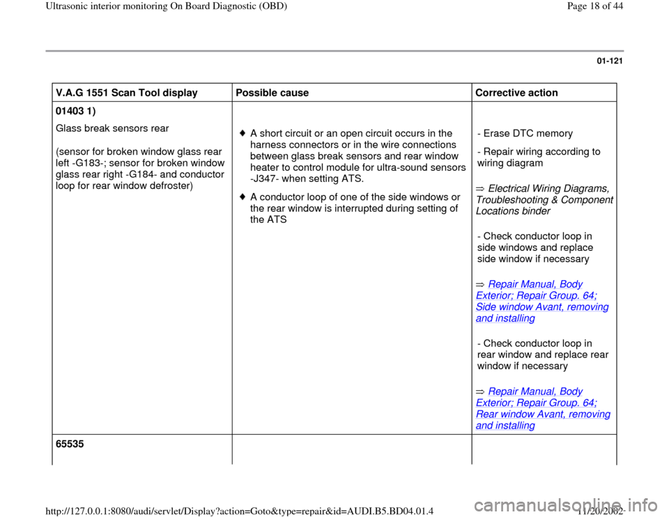
V.A.G 1551 Scan Tool display
Possible cause
Corrective action
01403 1)
Glass break sensors rear
(sensor for broken window glass rear
left -G183-; sensor for broken window
glass rear right -G184- and conductor
loop for rear window defroster)
A short circuit or an open circuit occurs in the
harness connectors or in the wire connections
between glass break sensors and rear window
heater to control module for ultra-sound sensors
-J347- when setting ATS. A conductor loop of one of the side windows or
the rear window is interrupted during setting of
the ATS Electrical Wiring Diagrams,
Troubleshooting & Component
Locations binder
Repair Manual, Body
Exterior; Repair Group. 64; Side window Avant, removing and installing
Repair Manual, Body
Exterior; Repair Group. 64; Rear window Avant, removing and installing
- Erase DTC memory
- Repair wiring according to
wiring diagram
- Check conductor loop in
side windows and replace
side window if necessary - Check conductor loop in
rear window and replace rear
window if necessary
65535
Pa
ge 18 of 44 Ultrasonic interior monitorin
g On Board Dia
gnostic
(OBD
)
11/20/2002 htt
p://127.0.0.1:8080/audi/servlet/Dis
play?action=Goto&t
yp
e=re
pair&id=AUDI.B5.BD04.01.4
Page 22 of 44
01-123
Check Control Module Versions (scan
tool function 01)
- Press buttons -0- and -1- to select "Check
Control Module Versions" function 01.
Rapid data transfer
Q
01 - Check Control Module Versions
Indicated on display
- Press -Q- button to confirm input.
4B0951173 Interior monitoring.
D00
Codin
g 00101
WSC 06812
Indicated on display
Explanation of display
4B0951173: Part No. of control moduleInterior monitoring: system identification and variationD00: software version Coding 00101: coding page 01
-131
WSC 06812: dealership number
- The program can be returned to the starting point by pressing the
button.
Rapid data transfer
HELP
Select function XX
Indicated on display
Pa
ge 22 of 44 Ultrasonic interior monitorin
g On Board Dia
gnostic
(OBD
)
11/20/2002 htt
p://127.0.0.1:8080/audi/servlet/Dis
play?action=Goto&t
yp
e=re
pair&id=AUDI.B5.BD04.01.4
Page 23 of 44
01-124
Output Diagnostic Test Mode (scan tool
function 03)
Notes:
The Output Diagnostic Test Mode may only be
performed with the vehicle stationary and the
engine not running.
Any malfunctions identified by the Output
Diagnostic Test Mode must be checked and
repaired.
Performing output Diagnostic Test Mode
(DTM):
Rapid data transfer
HELPSelect function X
X
Indicated on display:
- Press buttons -0- and -3- to select "Output Diagnostic Test Mode
(DTM)" function 03.
Rapid data transfer
Q03 - Output Dia
gnostic Test Mode
Indicated on display:
The output DTM activates the following elements in sequence: - Press -Q- button to confirm input.
Warning lamps next to door locking button on driver-side or
passenger-side door
Pa
ge 23 of 44 Ultrasonic interior monitorin
g On Board Dia
gnostic
(OBD
)
11/20/2002 htt
p://127.0.0.1:8080/audi/servlet/Dis
play?action=Goto&t
yp
e=re
pair&id=AUDI.B5.BD04.01.4
Page 26 of 44

01-126
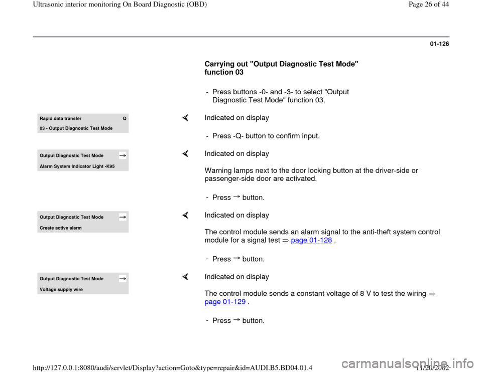
Carrying out "Output Diagnostic Test Mode"
function 03
- Press buttons -0- and -3- to select "Output
Diagnostic Test Mode" function 03. Rapid data transfer
Q
03 - Output Dia
gnostic Test Mode
Indicated on display
- Press -Q- button to confirm input.
Output Diagnostic Test Mode Alarm S
ystem Indicator Li
ght -K95
Indicated on display
Warning lamps next to the door locking button at the driver-side or
passenger-side door are activated.
-
Press button.
Output Diagnostic Test Mode Create active alarm
Indicated on display
The control module sends an alarm signal to the anti-theft system control
module for a signal test page 01
-128
.
-
Press button.
Output Diagnostic Test Mode Volta
ge suppl
y wire
Indicated on display
The control module sends a constant voltage of 8 V to test the wiring
page 01
-129
.
-
Press button.
Pa
ge 26 of 44 Ultrasonic interior monitorin
g On Board Dia
gnostic
(OBD
)
11/20/2002 htt
p://127.0.0.1:8080/audi/servlet/Dis
play?action=Goto&t
yp
e=re
pair&id=AUDI.B5.BD04.01.4
Page 27 of 44
01-127
Output Diagnostic Test Mode Wire for c
ycle si
gnal
Indicated on display
The control module sends a constant voltage of 5 V to test the wiring
page 01
-130
.
-
Press button.
Output Diagnostic Test Mode END
Indicated on display
The program is now back at its starting point. -
Press button.
Rapid data transfer
HELP
Select function XX
Indicated on display
Pa
ge 27 of 44 Ultrasonic interior monitorin
g On Board Dia
gnostic
(OBD
)
11/20/2002 htt
p://127.0.0.1:8080/audi/servlet/Dis
play?action=Goto&t
yp
e=re
pair&id=AUDI.B5.BD04.01.4
Page 29 of 44
The independent repair shop and the customer
can thereby test the functional capability of the
ultrasonic interior monitoring system.
Output Diagnostic Test Mode Create active alarm
Indicated on display
Specification: anti-theft system (turn signals and anti-theft horn) is
triggered.
Pa
ge 29 of 44 Ultrasonic interior monitorin
g On Board Dia
gnostic
(OBD
)
11/20/2002 htt
p://127.0.0.1:8080/audi/servlet/Dis
play?action=Goto&t
yp
e=re
pair&id=AUDI.B5.BD04.01.4