Page 9 of 35
17-9
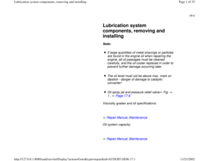
Repair Manual, Maintenance
17 -
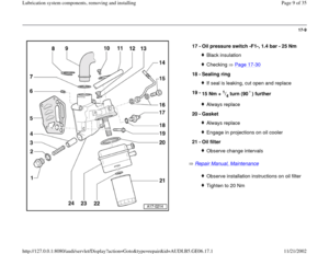
Oil pressure switch -F1-, 1.4 bar - 25 Nm
Black insulationChecking Page 17
-30
18 -
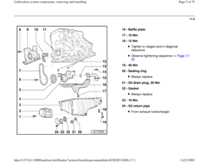
Sealing ring
If seal is leaking, cut open and replace
19 -
15 Nm +
1/4 turn (90 ) further
Always replace
20 -
Gasket Always replaceEngage in projections on oil cooler
21 -
Oil filter Observe change intervalsObserve installation instructions on oil filterTighten to 20 Nm
Pa
ge 9 of 35 Lubrication s
ystem com
ponents, removin
g and installin
g
11/21/2002 htt
p://127.0.0.1:8080/audi/servlet/Dis
play?action=Goto&t
yp
e=re
pair&id=AUDI.B5.GE06.17.1
Page 10 of 35
17-10
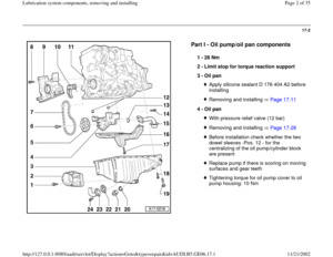
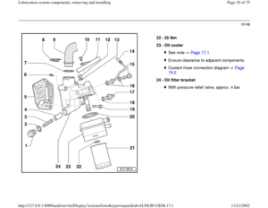
22 -
25 Nm
23 -
Oil cooler
See note Page 17
-1
Ensure clearance to adjacent componentsCoolant hose connection diagram Page 19
-2
24 -
Oil filter bracket
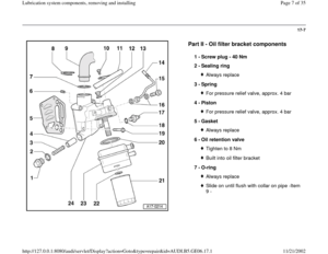
With pressure relief valve, approx. 4 bar
Pa
ge 10 of 35 Lubrication s
ystem com
ponents, removin
g and installin
g
11/21/2002 htt
p://127.0.0.1:8080/audi/servlet/Dis
play?action=Goto&t
yp
e=re
pair&id=AUDI.B5.GE06.17.1
Page 11 of 35
17-11
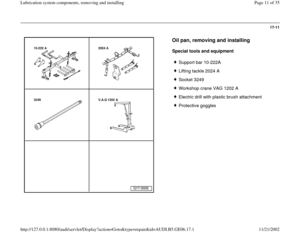
Oil pan, removing and installing
Special tools and equipment
Support bar 10-222A
Lifting tackle 2024 A
Socket 3249
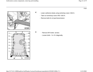
Workshop crane VAG 1202 A
Electric drill with plastic brush attachment
Protective goggles
Pa
ge 11 of 35 Lubrication s
ystem com
ponents, removin
g and installin
g
11/21/2002 htt
p://127.0.0.1:8080/audi/servlet/Dis
play?action=Goto&t
yp
e=re
pair&id=AUDI.B5.GE06.17.1
Page 12 of 35
17-12
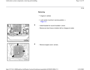
Removing
Engine in vehicle
Lock carrier must be in service position
Page 13
-1 .
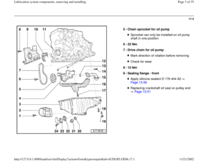
- Unbolt bracket for sound insulation -arrow-.
- Remove air duct hose on bottom left on charge air cooler.
- Remove engine cover -arrows-.
Pa
ge 12 of 35 Lubrication s
ystem com
ponents, removin
g and installin
g
11/21/2002 htt
p://127.0.0.1:8080/audi/servlet/Dis
play?action=Goto&t
yp
e=re
pair&id=AUDI.B5.GE06.17.1
Page 13 of 35
17-13
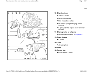
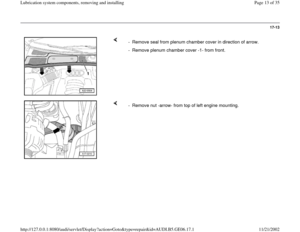
- Remove seal from plenum chamber cover in direction of arrow.
- Remove plenum chamber cover -1- from front.
- Remove nut -arrow- from top of left engine mounting.
Pa
ge 13 of 35 Lubrication s
ystem com
ponents, removin
g and installin
g
11/21/2002 htt
p://127.0.0.1:8080/audi/servlet/Dis
play?action=Goto&t
yp
e=re
pair&id=AUDI.B5.GE06.17.1
Page 14 of 35
17-14
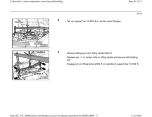
- Set up support bar 10-222 A on fender panel flanges.
- Remove lifting eye from lifting tackle 2024 A.
- Replace pin -1- in center hole on lifting tackle and secure with locking
pin.
- Engage pin on lifting tackle 2024 A on spindle of support bar 10-222 A.
Pa
ge 14 of 35 Lubrication s
ystem com
ponents, removin
g and installin
g
11/21/2002 htt
p://127.0.0.1:8080/audi/servlet/Dis
play?action=Goto&t
yp
e=re
pair&id=AUDI.B5.GE06.17.1
Page 15 of 35
17-15
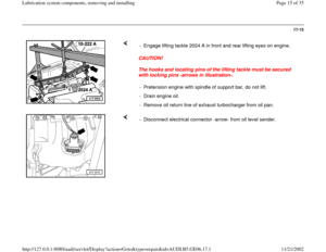
CAUTION!
The hooks and locating pins of the lifting tackle must be secured
with locking pins -arrows in illustration-. - Engage lifting tackle 2024 A in front and rear lifting eyes on engine.
- Pretension engine with spindle of support bar, do not lift.
- Drain engine oil.
- Remove oil return line of exhaust turbocharger from oil pan.
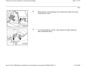
- Disconnect electrical connector -arrow- from oil level sender.
Pa
ge 15 of 35 Lubrication s
ystem com
ponents, removin
g and installin
g
11/21/2002 htt
p://127.0.0.1:8080/audi/servlet/Dis
play?action=Goto&t
yp
e=re
pair&id=AUDI.B5.GE06.17.1
Page 16 of 35
17-16
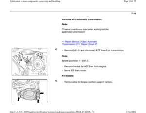
Vehicles with automatic transmission:
Note:
Observe cleanliness rules when working on the
automatic transmission:
Repair Manual, 5 Spd. Automatic
Transmission 01V, Repair Group 37
Note:
Ignore positions -1- and -2-.
All models: - Remove bolt -3- and disconnect ATF lines from transmission.
- Remove bracket for ATF lines from engine.
- Move ATF lines aside.
- Remove stop for torque reaction support -arrows-.
Pa
ge 16 of 35 Lubrication s
ystem com
ponents, removin
g and installin
g
11/21/2002 htt
p://127.0.0.1:8080/audi/servlet/Dis
play?action=Goto&t
yp
e=re
pair&id=AUDI.B5.GE06.17.1