1999 SUZUKI GRAND VITARA 7B1
[x] Cancel search: 7B1Page 4 of 656

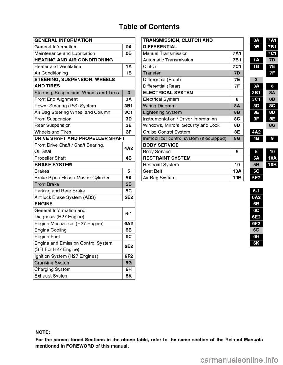
Table of Contents
GENERAL INFORMATION TRANSMISSION, CLUTCH AND
DIFFERENTIAL0A7A1
General Information0A
0B7B1
Maintenance and Lubrication0B
Manual Transmission7A1
7C1
HEATING AND AIR CONDITIONING
Automatic Transmission7B1
1A7D
Heater and Ventilation1A
Clutch7C1
1B7E
Air Conditioning1B
Transfer7D7F
STEERING, SUSPENSION, WHEELS
AND TIRESDifferential (Front)7E
3
Differential (Rear)7F
3A8
Steering, Suspension, Wheels and Tires3 ELECTRICAL SYSTEM3B18A
Front End Alignment3A
Electrical System8
3C18B
Power Steering (P/S) System3B1
Wiring Diagram8A3D8C
Air Bag Steering Wheel and Column3C1
Lightening System8B3E8D
Front Suspension3D
Instrumentation / Driver Information8C
3F8E
Rear Suspension3E
Windows, Mirrors, Security and Lock8D
8G
Wheels and Tires3F
Cruise Control System8E
4A2
DRIVE SHAFT AND PROPELLER SHAFT
Immobilizer control system (if equipped)8G4B9
Front Drive Shaft / Shaft Bearing,
Oil Seal4A2BODY SERVICE
Body Service9
510
Propeller Shaft4B RESTRAINT SYSTEM
5A10A
BRAKE SYSTEM
Restraint System10
5B10B
Brakes5
Seat Belt10A
5C
Brake Pipe / Hose / Master Cylinder5A
Air Bag System10B
5E2
Front Brake5B
Parking and Rear Brake5C
6-1
Antilock Brake System (ABS)5E2
6A2
ENGINE
6B
General Information and
Diagnosis (H27 Engine)6-1
6C
6E2
Engine Mechanical (H27 Engine)6A2
6F2
Engine Cooling6B
6G
Engine Fuel6C
6H
Engine and Emission Control System
(SFI For H27 Engine)6E2
6K
Ignition System (H27 Engines)6F2
Cranking System6G
Charging System6H
Exhaust System6K
NOTE:
For the screen toned Sections in the above table, refer to the same section of the Related Manuals
mentioned in FOREWORD of this manual.
Page 162 of 656

ENGINE GENERAL INFORMATION AND DIAGNOSIS (H27 ENGINE) 6-1-1
6-1
SECTION 6-1
ENGINE GENERAL INFORMATION AND
DIAGNOSIS (H27 ENGINE)
CONTENTS
General Information ...................................... 6-1-3
Statement of Cleanliness and Care ............ 6-1-3
General Information on Engine Service ...... 6-1-3
Precaution on Fuel System Service ............ 6-1-4
Fuel Pressure Relief Procedure .................. 6-1-5
Fuel Leakage Check Procedure .................. 6-1-5
Engine Diagnosis .......................................... 6-1-6
General Description .................................... 6-1-6
On-Board Diagnostic System (Vehicle
without Monitor Connector) ......................... 6-1-6
On-Board Diagnostic System (Vehicle with
Monitor Connector) ..................................... 6-1-9
Precaution in Diagnosing Trouble ............. 6-1-10
Engine Diagnostic Flow Table ................... 6-1-11
Malfunction Indicator Lamp (MIL) Check... 6-1-16
Diagnostic Trouble Code (DTC) Check ..... 6-1-16
Diagnostic Trouble Code (DTC) Clearance 6-1-17
Diagnostic Trouble Code (DTC) Table ...... 6-1-18For A/T system (Refer to Section 7B1
for diagnosis)......................................... 6-1-21
For immobilizer control system (Refer to
Section 8G for diagnosis) ...................... 6-1-22
Fail-Safe Table.......................................... 6-1-23
Scan Tool Data ......................................... 6-1-24
Scan tool data definitions ...................... 6-1-27
Engine Diagnosis Table ............................ 6-1-31
Inspection of PCM (ECM) and its Circuits. 6-1-36
Table A-1 Malfunction Indicator Lamp
Circuit Check – Lamp Does Not Come
“ON” or Dims at Ignition Switch ON
(But Engine at Stop).................................. 6-1-43
Table A-2 Malfunction Indicator Lamp
Circuit Check – Lamp Remains “ON” after
Engine Starts ............................................ 6-1-44
Table A-3 Malfunction Indicator Lamp
Check – MIL Flashes at Ignition Switch
ON (Vehicle with Monitor Connector) ....... 6-1-45 WARNING:
For vehicles equipped with Supplemental Restraint (Air Bag) System:
Service on and around the air bag system components or wiring must be performed only by an
authorized SUZUKI dealer. Refer to “Air Bag System Components and Wiring Location View” under
“General Description” in air bag system section in order to confirm whether you are performing ser-
vice on or near the air bag system components or wiring. Please observe all WARNINGS and “Ser-
vice Precautions” under “On-Vehicle Service” in air bag system section before performing service
on or around the air bag system components or wiring. Failure to follow WARNINGS could result in
unintentional activation of the system or could render the system inoperative. Either of these two
conditions may result in severe injury.
Technical service work must be started at least 90 seconds after the ignition switch is turned to the
“LOCK” position and the negative cable is disconnected from the battery. Otherwise, the system
may be activated by reserve energy in the Sensing and Diagnostic Module (SDM).
NOTE:
Whether following systems (parts) are used in the particular vehicle or not depends on specifications.
Be sure to bear this in mind when performing service work.
Monitor connector
CKP sensor
MAP sensor
EGR valve
Heated oxygen sensor or CO adjusting resistor
Three way catalytic converter, Warm-up three way catalytic converter
Page 174 of 656

ENGINE GENERAL INFORMATION AND DIAGNOSIS (H27 ENGINE) 6-1-13
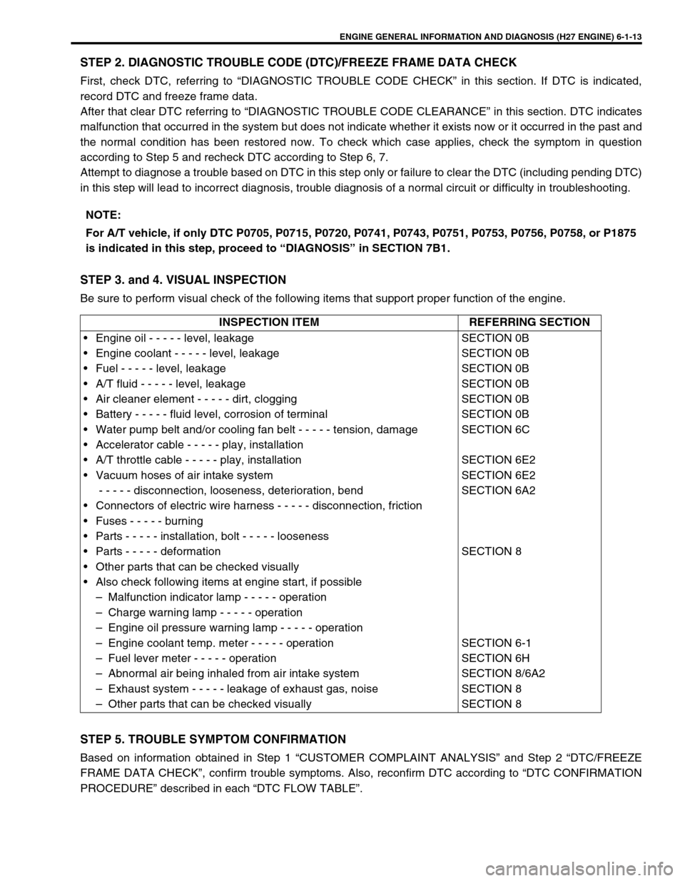
STEP 2. DIAGNOSTIC TROUBLE CODE (DTC)/FREEZE FRAME DATA CHECK
First, check DTC, referring to “DIAGNOSTIC TROUBLE CODE CHECK” in this section. If DTC is indicated,
record DTC and freeze frame data.
After that clear DTC referring to “DIAGNOSTIC TROUBLE CODE CLEARANCE” in this section. DTC indicates
malfunction that occurred in the system but does not indicate whether it exists now or it occurred in the past and
the normal condition has been restored now. To check which case applies, check the symptom in question
according to Step 5 and recheck DTC according to Step 6, 7.
Attempt to diagnose a trouble based on DTC in this step only or failure to clear the DTC (including pending DTC)
in this step will lead to incorrect diagnosis, trouble diagnosis of a normal circuit or difficulty in troubleshooting.
STEP 3. and 4. VISUAL INSPECTION
Be sure to perform visual check of the following items that support proper function of the engine.
STEP 5. TROUBLE SYMPTOM CONFIRMATION
Based on information obtained in Step 1 “CUSTOMER COMPLAINT ANALYSIS” and Step 2 “DTC/FREEZE
FRAME DATA CHECK”, confirm trouble symptoms. Also, reconfirm DTC according to “DTC CONFIRMATION
PROCEDURE” described in each “DTC FLOW TABLE”.NOTE:
For A/T vehicle, if only DTC P0705, P0715, P0720, P0741, P0743, P0751, P0753, P0756, P0758, or P1875
is indicated in this step, proceed to “DIAGNOSIS” in SECTION 7B1.
INSPECTION ITEM REFERRING SECTION
• Engine oil - - - - - level, leakage
• Engine coolant - - - - - level, leakage
• Fuel - - - - - level, leakage
• A/T fluid - - - - - level, leakage
• Air cleaner element - - - - - dirt, clogging
• Battery - - - - - fluid level, corrosion of terminal
• Water pump belt and/or cooling fan belt - - - - - tension, damage
• Accelerator cable - - - - - play, installation
• A/T throttle cable - - - - - play, installation
• Vacuum hoses of air intake system
- - - - - disconnection, looseness, deterioration, bend
• Connectors of electric wire harness - - - - - disconnection, friction
• Fuses - - - - - burning
• Parts - - - - - installation, bolt - - - - - looseness
• Parts - - - - - deformation
• Other parts that can be checked visually
• Also check following items at engine start, if possible
– Malfunction indicator lamp - - - - - operation
– Charge warning lamp - - - - - operation
– Engine oil pressure warning lamp - - - - - operation
– Engine coolant temp. meter - - - - - operation
– Fuel lever meter - - - - - operation
– Abnormal air being inhaled from air intake system
– Exhaust system - - - - - leakage of exhaust gas, noise
– Other parts that can be checked visuallySECTION 0B
SECTION 0B
SECTION 0B
SECTION 0B
SECTION 0B
SECTION 0B
SECTION 6C
SECTION 6E2
SECTION 6E2
SECTION 6A2
SECTION 8
SECTION 6-1
SECTION 6H
SECTION 8/6A2
SECTION 8
SECTION 8
Page 182 of 656

ENGINE GENERAL INFORMATION AND DIAGNOSIS (H27 ENGINE) 6-1-21
For A/T system (Refer to Section 7B1 for diagnosis)
P0505Idle air control system mal-
functionDifference between desired idle speed
and actual idle speed continues to
exceed specified value for longer than
specified time.2 driving
cyclesNot
applicable
P0601
(No.71)Internal control module mem-
ory check sum errorData write error (or check sum error)
when written into ECM1 driving
cycle1 driving
cycle
P1408Manifold absolute pressure
sensor circuit malfunctionManifold absolute pressure sensor
output voltage is higher or lower than
specified value (or sensor circuit
shorted to ground or open).2 driving
cyclesNot
applicable
P1450Barometric pressure sensor
circuit malfunctionBarometric pressure is lower or higher
than specification.1 driving
cycleNot
applicable
P1451Barometric pressure sensor
performance problemDifference between intake manifold
pressure and barometric pressure is
larger than specification.2 driving
cyclesNot
applicable
P1500Engine starter signal circuit
malfunctionEngine starts with no starter signal or
signal input during long period after
start.2 driving
cyclesNot
applicable
P1510ECM back-up power supply
malfunctionNo back-up power after starting
engine.1 driving
cycleNot
applicable DTC NO. DETECTED ITEMDETECTING CONDITION
(DTC will set when detecting : )MIL
(vehicle
without
monitor
connector)MIL
(vehicle
with
monitor
connector)
DTC NO. DETECTED ITEMDETECTING CONDITION
(DTC will set when detecting : )MIL
(vehicle
without
monitor
connector)MIL
(vehicle
with
monitor
connector)
P0705
(No.72)Transmission range switch cir-
cuit malfunctionMultiple signals inputted simulta-
neously or P, R, N, D, 2 or L range sig-
nal not inputted while running at
60km/h or more.2 driving
cyclesNot
applicable
P0715
(No.76)Input speed sensor circuit
malfunctionInput speed sensor signal is lower
than specification while running.2 driving
cyclesNot
applicable
P0720
(No.75)Output speed sensor circuit
malfunctionOutput speed sensor signal not input-
ted while VSS signal being inputted.2 driving
cyclesNot
applicable
P0741TCC (lock-up) solenoid perfor-
mance or stuck offActual TCC operation does not agree
with ON/OFF control from PCM to
TCC.2 driving
cyclesNot
applicable
P0743
(No.65)
(No.66)TCC (lock-up) solenoid electri-
calMonitor signal OFF is detected when
TCC control solenoid is ON or monitor
signal ON is detected when it is OFF.1 driving
cycleNot
applicable
P0751Shift solenoid A (#1) perfor-
mance or stuck offGear change control from PCM to A/T
does not agree with actual gear posi-
tion of A/T.2 driving
cyclesNot
applicable
Page 410 of 656

AUTOMATIC TRANSMISSION (4 A/T) 7B1-1
7B1
SECTION 7B1
AUTOMATIC TRANSMISSION (4 A/T)
CONTENTS
General Description ......................................7B1-3
Electronic Shift Control System ................... 7B1-4
Automatic gear shift diagram................... 7B1-5
Diagnosis .......................................................7B1-7
On-Board Diagnostic System
(Vehicle without monitor connector) ............ 7B1-7
On-Board Diagnostic System
(Vehicle with monitor connector) ................. 7B1-8
Precaution in Diagnosing Trouble ............... 7B1-9
Automatic Transmission Diagnostic Flow
Table ......................................................... 7B1-10
Malfunction Indicator Lamp (MIL) Check... 7B1-13
“O/D OFF” Lamp Check ............................ 7B1-13
“POWER” Lamp Check ............................. 7B1-13
Diagnostic Trouble Code (DTC) Check ..... 7B1-13
Diagnostic Trouble Code Clearance ......... 7B1-13
Diagnostic Trouble Code Table ................. 7B1-14
Fail Safe Table .......................................... 7B1-14
Visual Inspection ....................................... 7B1-14
A/T Basic Check ........................................ 7B1-14
Trouble Diagnosis Table 1 ........................ 7B1-15
Trouble Diagnosis Table 2 ........................ 7B1-15
Trouble Diagnosis Table 3 ........................ 7B1-16
Scan Tool Data ......................................... 7B1-17
Inspection of PCM and Its Circuit .............. 7B1-17Wire Harness and Connectors .................. 7B1-17
Table A-1 : No TCC Lock-Up Occurs ........ 7B1-18
Table A-2 : No Gear Shift to O/D .............. 7B1-20
Table B-1 : “O/D OFF” Light Circuit Check
(“O/D OFF” Light Doesn’t Light at Ignition
Switch ON But Engine Starts Up) ............. 7B1-22
Table B-2 : “O/D OFF” Light Circuit Check
(“O/D OFF” Light Comes ON Steadily) ..... 7B1-23
Table B-3 : “POWER” Light Circuit Check
(“POWER” Light Doesn’t Light at Ignition
Switch ON But Engine Starts Up) ............. 7B1-24
Table B-4 : “POWER” Light Circuit Check
(“POWER” Light Comes ON Steadily) ...... 7B1-25
DTC P0705 (DTC NO.72) - Transmission
Range Sensor (Switch) Circuit Malfunction7B1-26
DTC P0715 (DTC NO.76) - Input/Turbine
Speed Sensor Circuit Malfunction............. 7B1-29
DTC P0720 (DTC NO.75) Output Speed
Sensor Circuit Malfunction ........................ 7B1-32
DTC P0743 (DTC NO.65/66) -
TCC (Lock-Up) Solenoid Electrical ........... 7B1-34
DTC P0753 (DTC NO.61/62)
Shift Solenoid-A (#1) Electrical
DTC P0758 (DTC NO.63/64)
Shift Solenoid-B (#2) Electrical ................. 7B1-36 WARNING:
For vehicles equipped with Supplemental Restraint (Air Bag) System:
Service on and around the air bag system components or wiring must be performed only by an
authorized SUZUKI dealer. Refer to “Air Bag System Components and Wiring Location View” under
“General Description” in air bag system section in order to confirm whether you are performing ser-
vice on or near the air bag system components or wiring. Please observe all WARNINGS and “Ser-
vice Precautions” under “On-Vehicle Service” in air bag system section before performing service
on or around the air bag system components or wiring. Failure to follow WARNINGS could result in
unintentional activation of the system or could render the system inoperative. Either of these two
conditions may result in severe injury.
Technical service work must be started at least 90 seconds after the ignition switch is turned to the
“LOCK” position and the negative cable is disconnected from the battery. Otherwise, the system
may be activated by reserve energy in the Sensing and Diagnostic Module (SDM).
NOTE:
For the descriptions (items) not found in this section, refer to the same section of the Service Manual
mentioned in FOREWORD of this manual.
Page 411 of 656

7B1-2 AUTOMATIC TRANSMISSION (4 A/T)
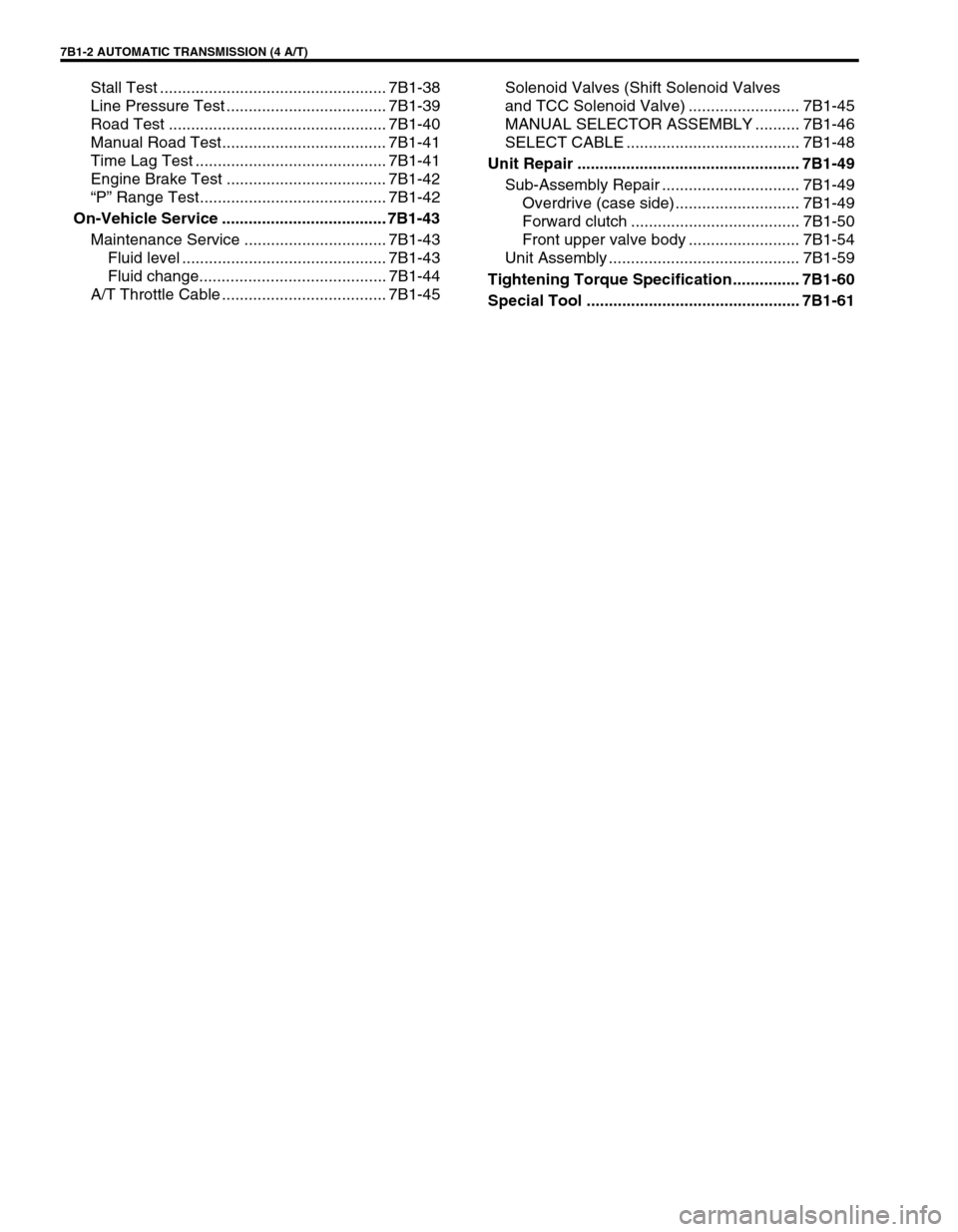
Stall Test ................................................... 7B1-38
Line Pressure Test .................................... 7B1-39
Road Test ................................................. 7B1-40
Manual Road Test..................................... 7B1-41
Time Lag Test ........................................... 7B1-41
Engine Brake Test .................................... 7B1-42
“P” Range Test.......................................... 7B1-42
On-Vehicle Service ..................................... 7B1-43
Maintenance Service ................................ 7B1-43
Fluid level .............................................. 7B1-43
Fluid change.......................................... 7B1-44
A/T Throttle Cable ..................................... 7B1-45Solenoid Valves (Shift Solenoid Valves
and TCC Solenoid Valve) ......................... 7B1-45
MANUAL SELECTOR ASSEMBLY .......... 7B1-46
SELECT CABLE ....................................... 7B1-48
Unit Repair .................................................. 7B1-49
Sub-Assembly Repair ............................... 7B1-49
Overdrive (case side) ............................ 7B1-49
Forward clutch ...................................... 7B1-50
Front upper valve body ......................... 7B1-54
Unit Assembly ........................................... 7B1-59
Tightening Torque Specification............... 7B1-60
Special Tool ................................................ 7B1-61
Page 412 of 656

AUTOMATIC TRANSMISSION (4 A/T) 7B1-3
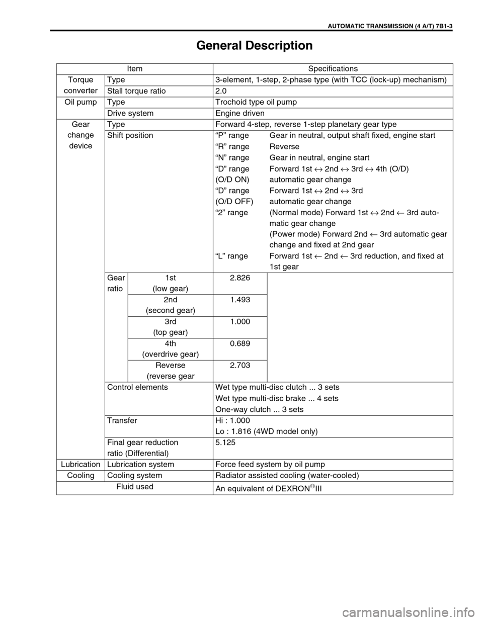
General Description
Item Specifications
Torque
converterType 3-element, 1-step, 2-phase type (with TCC (lock-up) mechanism)
Stall torque ratio 2.0
Oil pump Type Trochoid type oil pump
Drive system Engine driven
Gear
change
deviceType Forward 4-step, reverse 1-step planetary gear type
Shift position“P” range Gear in neutral, output shaft fixed, engine start
“R” range Reverse
“N” range Gear in neutral, engine start
“D” range
(O/D ON)Forward 1st ↔ 2nd ↔ 3rd ↔ 4th (O/D)
automatic gear change
“D” range
(O/D OFF)Forward 1st ↔ 2nd ↔ 3rd
automatic gear change
“2” range (Normal mode) Forward 1st ↔ 2nd ← 3rd auto-
matic gear change
(Power mode) Forward 2nd ← 3rd automatic gear
change and fixed at 2nd gear
“L” range Forward 1st ← 2nd ← 3rd reduction, and fixed at
1st gear
Gear
ratio1st
(low gear)2.826
2nd
(second gear)1.493
3rd
(top gear)1.000
4th
(overdrive gear)0.689
Reverse
(reverse gear2.703
Control elements Wet type multi-disc clutch ... 3 sets
Wet type multi-disc brake ... 4 sets
One-way clutch ... 3 sets
Transfer Hi : 1.000
Lo : 1.816 (4WD model only)
Final gear reduction
ratio (Differential)5.125
Lubrication Lubrication system Force feed system by oil pump
Cooling Cooling system Radiator assisted cooling (water-cooled)
Fluid used
An equivalent of DEXRON
III
Page 413 of 656

7B1-4 AUTOMATIC TRANSMISSION (4 A/T)
Electronic Shift Control System
1. PCM (ECM) 9. Transmission range sensor 17. MIL (“SERVICE ENGINE SOON” lamp)
2. VSS 10. Shift solenoid-A 18. O/D off switch
3. CMP sensor 11. Shift solenoid-B 19. P/N change switch
4. TP sensor 12. TCC solenoid 20. 4WD low switch
5. ECT sensor 13. Data link connector 21. Main relay
6. Stop lamp switch 14. Cruise control module 22. Ignition switch
7. Input shaft speed sensor 15.“POWER” lamp 23. Battery
8. Output shaft speed sensor 16.“O/D OFF” lamp 24. PCM (ECM) connector terminal (viewed from harness side)
5V
5V5V
5V5V
5V
5V 5V C51-1-14
C51-1-12
C51-1-13
C51-3-26
C51-3-12
C51-3-13
C51-3-9
C51-3-2
C51-3-24
C51-1-11
C51-1-10
C51-1-20 C51-1-21
C51-1-23
C51-1-22
C51-1-7
C51-1-6
C51-1-19
C51-1-18
C51-1-28
C51-1-27
C51-1-2
C51-1-1
C51-1-8
E61-13
E61-35
E61-4C51-1-26 E61-31 E61-33 E61-21 E61-20 E61-7
C51-3-20
E61-2
E61-9
C51-3-4
C51-3-15
C51-3-6
C51-3-17
C51-2-7
12V
12V 12V 12V
12V
12V
12V
12V
5V
12V
BLU/YEL
YEL/GRN
YEL/BLU
GRY/YEL
GRY/YEL
GRY/RED
RED/GRN
ORN/BLU
GRY/YEL
BLU/YEL
BLU/GRN
WHT
ORN
ORN/GRN
RED P
R
N
D
2
LORN/BLU
YEL/GRN
GRN/ORN
GRN/BLU
GRN
GRN/RED
GRN/YEL
PPL/RED
PNK/BLU
GRY
PPL/YEL
WHT/BLK
GRY/BLU
YEL/RED
ORN/BLU
WHT
BLU
BLU/BLK
BLU/BLK
BLK/GRN
BLK/ORN
BLK/GRNBLK/WHT ORN/WHT
8
7
23 22
35 346
20 21
335
19
3218
3117
3016 15
2914
284
13
273
12
26112
10
256
5
17 16
26 252
1
98
21 202
1
98
22 21 1
9
247
20
306
19
2918
27 17
2816 15
2614
25 5
13 4
12
24113
10
23 7
19
28654 3
18
2717 16
2615 14
2513
2412
2311
2210 4
15 14
2413
2312
2211 10 9 8 7
213
202
191
18
24
E61 C51-3 C51-1 C51-2 14
13
B+
B+
17
16
15
18
19
20
22
21
23
BB+
IG1
B+
IG2
1 2
3
4
5
7 6
8
IG1
9
10
11
12
BB+
E61-34 GRN/WHT
BB+