Page 361 of 656

6E2-28 ENGINE AND EMISSION CONTROL SYSTEM (SEQUENTIAL MULTIPORT FUEL INJECTION FOR H27 ENGINE)
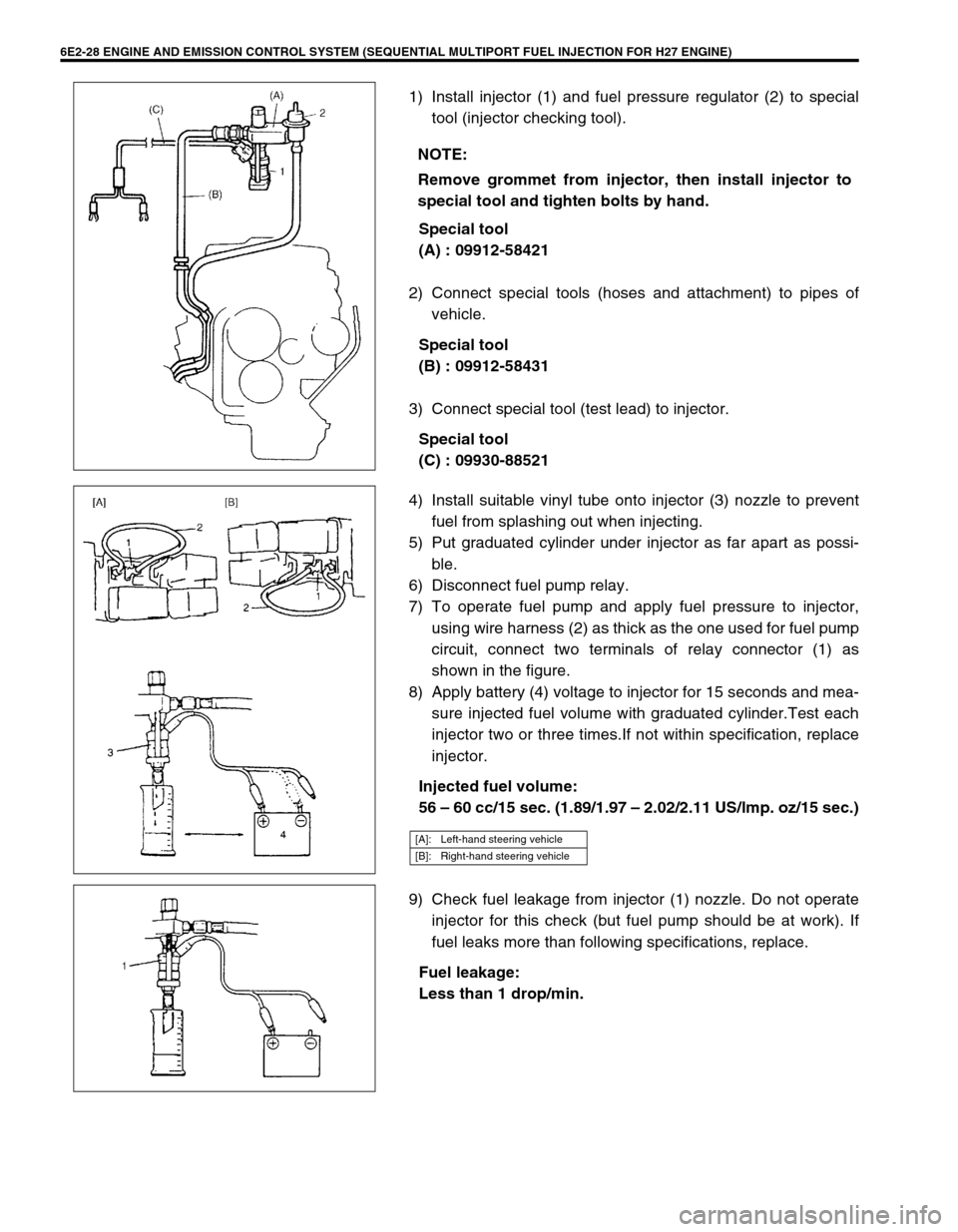
1) Install injector (1) and fuel pressure regulator (2) to special
tool (injector checking tool).
Special tool
(A) : 09912-58421
2) Connect special tools (hoses and attachment) to pipes of
vehicle.
Special tool
(B) : 09912-58431
3) Connect special tool (test lead) to injector.
Special tool
(C) : 09930-88521
4) Install suitable vinyl tube onto injector (3) nozzle to prevent
fuel from splashing out when injecting.
5) Put graduated cylinder under injector as far apart as possi-
ble.
6) Disconnect fuel pump relay.
7) To operate fuel pump and apply fuel pressure to injector,
using wire harness (2) as thick as the one used for fuel pump
circuit, connect two terminals of relay connector (1) as
shown in the figure.
8) Apply battery (4) voltage to injector for 15 seconds and mea-
sure injected fuel volume with graduated cylinder.Test each
injector two or three times.If not within specification, replace
injector.
Injected fuel volume:
56 – 60 cc/15 sec. (1.89/1.97 – 2.02/2.11 US/lmp. oz/15 sec.)
9) Check fuel leakage from injector (1) nozzle. Do not operate
injector for this check (but fuel pump should be at work). If
fuel leaks more than following specifications, replace.
Fuel leakage:
Less than 1 drop/min. NOTE:
Remove grommet from injector, then install injector to
special tool and tighten bolts by hand.
[A]: Left-hand steering vehicle
[B]: Right-hand steering vehicle
Page 373 of 656

6E2-40 ENGINE AND EMISSION CONTROL SYSTEM (SEQUENTIAL MULTIPORT FUEL INJECTION FOR H27 ENGINE)
INSPECTION
1) Check sensor O-ring (1) for damage and deterioration.
Replace as necessary.
2) Arrange 3 new 1.5 V batteries (2) in series and connect its
positive terminal to “Vin” terminal of MAP sensor (1) and
negative terminal to “Ground” terminal. Then check voltage
between “Vout” and “Ground”.
Also, check if voltage reduces when vacuum is slowly
applied up to 400 mmHg by using vacuum pump (3).
If check result is not satisfactory, replace manifold absolute
pressure sensor.
MAP sensor output voltage (Vin voltage 4.5 – 5.5 V, ambi-
ent temp. 20 – 30°C (68 – 86°F))
CAUTION:
As connection to wrong terminal will cause damage to
manifold absolute pressure sensor, make absolutely sure
to connect properly as shown in the figure.
ALTITUDE
(Reference)BAROMETRIC
PRESSUREOUTPUT
VOLTAGE
(ft) (m) (mmHg) (kPa) (V)
0
–
20000
–
610760
–
707100 – 94 3.3 – 4.3
2001
–
5000611
–
1524Under 707
over 63494 – 85 3.0 – 4.1
5001
–
80001525
–
2438Under 634
over 56785 – 76 2.7 – 3.7
8001
–
100002439
–
3048Under 567
over 52676 – 70 2.5 – 3.3
Page 374 of 656
ENGINE AND EMISSION CONTROL SYSTEM (SEQUENTIAL MULTIPORT FUEL INJECTION FOR H27 ENGINE) 6E2-41
INSTALLATION
1) Confirm that vacuum passage on intake manifold is free from
clog.
2) Apply engine oil to O-ring of sensor.
3) Install sensor (1) to intake manifold (2).
4) Connect connector to sensor (1) securely.
Fuel level sensor (sender gauge)
Refer to Section 8C.
Crankshaft position sensor
REMOVAL AND INSTALLATION
Refer to Section 6A4.
INSPECTION
Refer to Section 6-1.
Main relay
INSPECTION
1) Disconnect negative (–) cable at battery.
2) Remove main relay (1) from its connector.
2. Fuel pump relay
3. Fuse box
4. Instrument panel
[A]: Left-hand steering vehicle
[B]: Right-hand steering vehicle
Page 375 of 656
6E2-42 ENGINE AND EMISSION CONTROL SYSTEM (SEQUENTIAL MULTIPORT FUEL INJECTION FOR H27 ENGINE)
3) Check resistance between each two terminals as in table
below.
If check results are as specified, proceed to next operation
check. If not, replace.
Main relay resistance:
4) Check that there is continuity between terminals “A” and “B”
when battery is connected to terminals “C” and “D”.
If malfunction is found, replace.
Fuel pump relay
INSPECTION
1) Disconnect negative (–) cable at battery.
2) Remove fuel pump relay (2) from connector.
3) Structure of fuel pump relay is the same as that of main
relay.
Check its resistance and operation using the same proce-
dure as that for main relay.
If malfunction is found, replace. TERMINALS RESISTANCE
Between “A” and “B”∞
∞∞ ∞ (Infinity)
Between “C” and “D”
79 – 95 Ω
ΩΩ Ω (at 20
°C (68°F))
1. Main relay
3. Fuse box
4. Instrument panel
[A]: Left-hand steering vehicle
[B]: Right-hand steering vehicle
Page 382 of 656

ENGINE AND EMISSION CONTROL SYSTEM (SEQUENTIAL MULTIPORT FUEL INJECTION FOR H27 ENGINE) 6E2-49
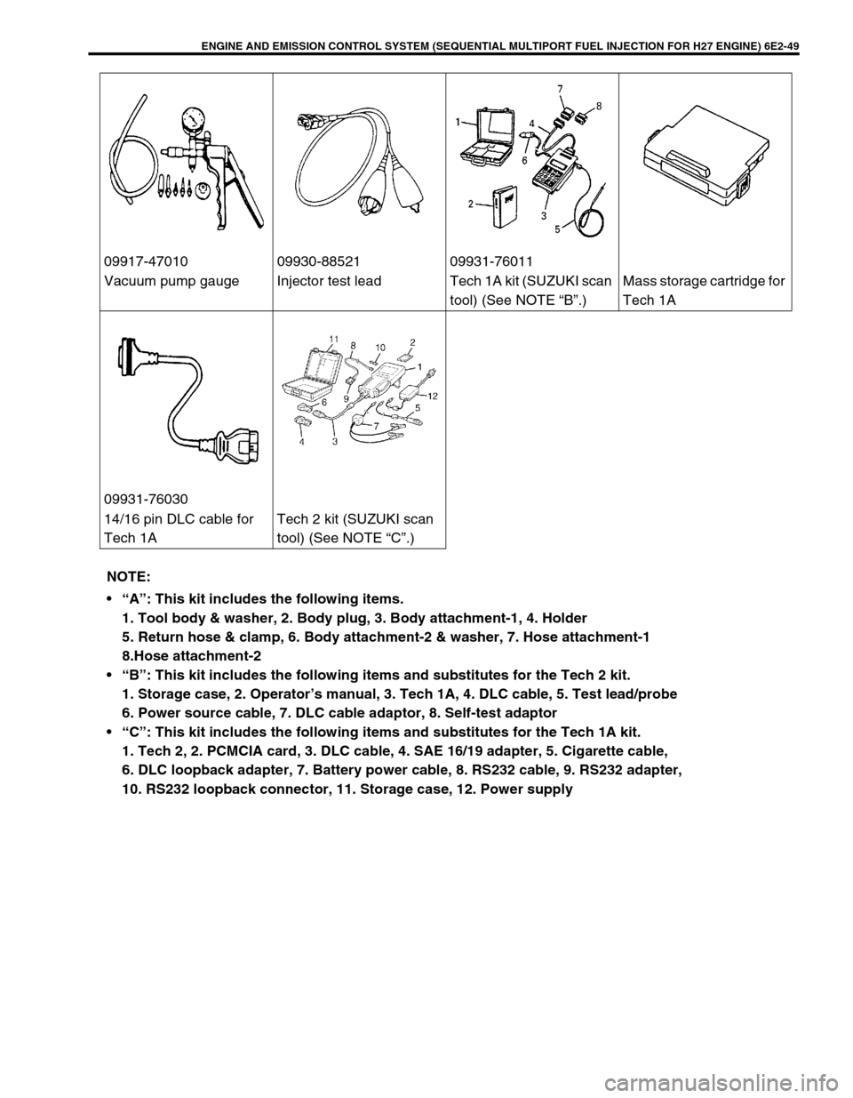
09917-47010 09930-88521 09931-76011
Vacuum pump gauge Injector test lead Tech 1A kit (SUZUKI scan
tool) (See NOTE “B”.)Mass storage cartridge for
Tech 1A
09931-76030
14/16 pin DLC cable for
Tech 1ATech 2 kit (SUZUKI scan
tool) (See NOTE “C”.)
NOTE:
“A”: This kit includes the following items.
1. Tool body & washer, 2. Body plug, 3. Body attachment-1, 4. Holder
5. Return hose & clamp, 6. Body attachment-2 & washer, 7. Hose attachment-1
8.Hose attachment-2
“B”: This kit includes the following items and substitutes for the Tech 2 kit.
1. Storage case, 2. Operator’s manual, 3. Tech 1A, 4. DLC cable, 5. Test lead/probe
6. Power source cable, 7. DLC cable adaptor, 8. Self-test adaptor
“C”: This kit includes the following items and substitutes for the Tech 1A kit.
1. Tech 2, 2. PCMCIA card, 3. DLC cable, 4. SAE 16/19 adapter, 5. Cigarette cable,
6. DLC loopback adapter, 7. Battery power cable, 8. RS232 cable, 9. RS232 adapter,
10. RS232 loopback connector, 11. Storage case, 12. Power supply
Page 479 of 656

7E-6 DIFFERENTIAL (FRONT)
4WD Control System Inspection
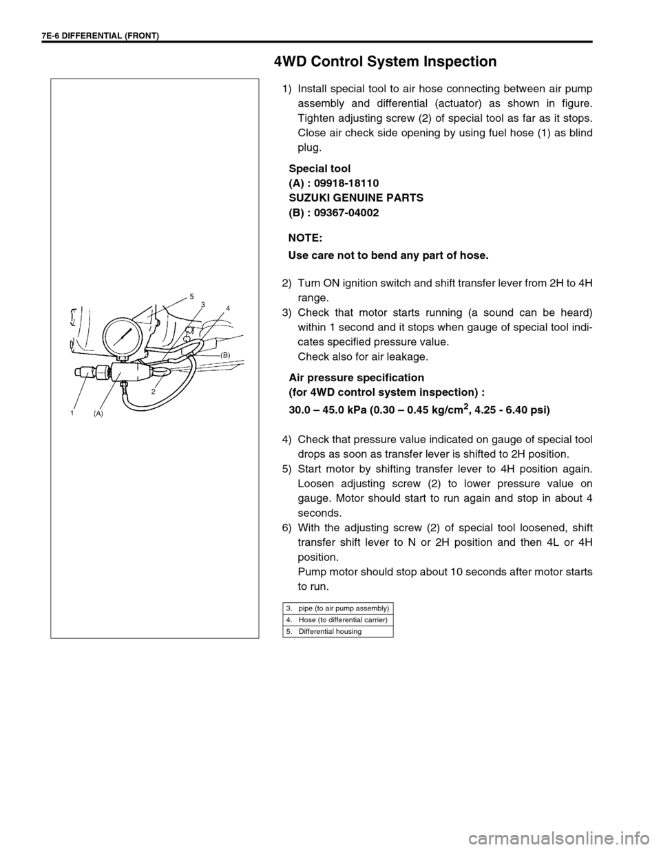
1) Install special tool to air hose connecting between air pump
assembly and differential (actuator) as shown in figure.
Tighten adjusting screw (2) of special tool as far as it stops.
Close air check side opening by using fuel hose (1) as blind
plug.
Special tool
(A) : 09918-18110
SUZUKI GENUINE PARTS
(B) : 09367-04002
2) Turn ON ignition switch and shift transfer lever from 2H to 4H
range.
3) Check that motor starts running (a sound can be heard)
within 1 second and it stops when gauge of special tool indi-
cates specified pressure value.
Check also for air leakage.
Air pressure specification
(for 4WD control system inspection) :
30.0 – 45.0 kPa (0.30 – 0.45 kg/cm
2, 4.25 - 6.40 psi)
4) Check that pressure value indicated on gauge of special tool
drops as soon as transfer lever is shifted to 2H position.
5) Start motor by shifting transfer lever to 4H position again.
Loosen adjusting screw (2) to lower pressure value on
gauge. Motor should start to run again and stop in about 4
seconds.
6) With the adjusting screw (2) of special tool loosened, shift
transfer shift lever to N or 2H position and then 4L or 4H
position.
Pump motor should stop about 10 seconds after motor starts
to run. NOTE:
Use care not to bend any part of hose.
3. pipe (to air pump assembly)
4. Hose (to differential carrier)
5. Differential housing
Page 515 of 656
8C-4 INSTRUMENTATION/DRIVER INFORMATION
On-vehicle Service
Fuel Meter/Fuel Gauge Unit
Fuel level sensor (sender gauge)
INSPECTION
Remove fuel pump assembly referring to Section 6C.
Use an ohmmeter to confirm that resistance of sender gauge unit
changes with change of float position.
If measured value is out of specification, replace fuel sender
gauge.
Fuel level sensor specification :
Float Position Resistance (Ω
ΩΩ Ω)
“a”53.6 mm
(2.11 in.)6 – 8
“b”143.1 mm
(5.63 in.)28 – 36
“c”256.9 mm
(10.11 in.)90 – 100
1. Fuel pump assembly
2. Fuel level gauge (–) terminal
3. Fuel level gauge (+) terminal
4. Float