Page 461 of 656
7B1-52 AUTOMATIC TRANSMISSION (4 A/T)
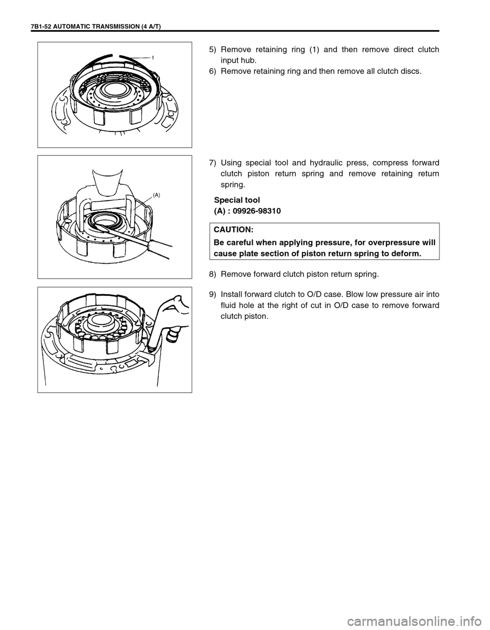
5) Remove retaining ring (1) and then remove direct clutch
input hub.
6) Remove retaining ring and then remove all clutch discs.
7) Using special tool and hydraulic press, compress forward
clutch piston return spring and remove retaining return
spring.
Special tool
(A) : 09926-98310
8) Remove forward clutch piston return spring.
9) Install forward clutch to O/D case. Blow low pressure air into
fluid hole at the right of cut in O/D case to remove forward
clutch piston.
CAUTION:
Be careful when applying pressure, for overpressure will
cause plate section of piston return spring to deform.
Page 462 of 656
AUTOMATIC TRANSMISSION (4 A/T) 7B1-53
DIRECT CLUTCH
DISASSEMBLY
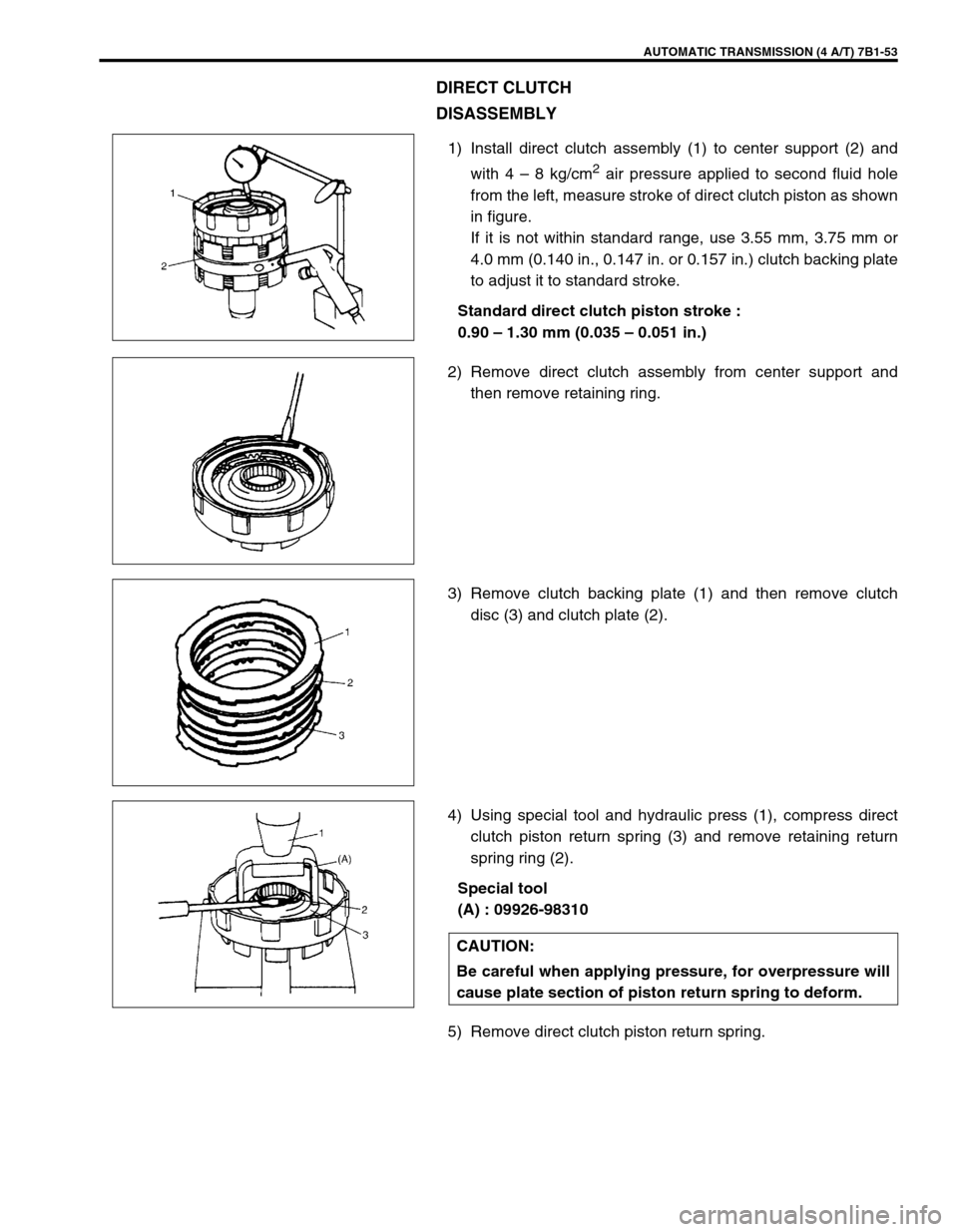
1) Install direct clutch assembly (1) to center support (2) and
with 4 – 8 kg/cm
2 air pressure applied to second fluid hole
from the left, measure stroke of direct clutch piston as shown
in figure.
If it is not within standard range, use 3.55 mm, 3.75 mm or
4.0 mm (0.140 in., 0.147 in. or 0.157 in.) clutch backing plate
to adjust it to standard stroke.
Standard direct clutch piston stroke :
0.90 – 1.30 mm (0.035 – 0.051 in.)
2) Remove direct clutch assembly from center support and
then remove retaining ring.
3) Remove clutch backing plate (1) and then remove clutch
disc (3) and clutch plate (2).
4) Using special tool and hydraulic press (1), compress direct
clutch piston return spring (3) and remove retaining return
spring ring (2).
Special tool
(A) : 09926-98310
5) Remove direct clutch piston return spring.
CAUTION:
Be careful when applying pressure, for overpressure will
cause plate section of piston return spring to deform.
Page 468 of 656
AUTOMATIC TRANSMISSION (4 A/T) 7B1-59
•Tighten TCC (lock-up) solenoid valve bolt to specified
torque.
Tightening torque
TCC solenoid valve bolt :
5.5 N·m (0.55 kg-m, 4.0 lb-ft)
•Tighten pressure relief valve bolt to specified torque.
Tightening torque
Pressure relief valve bolt :
5.5 N·m (0.55 kg-m, 4.0 lb-ft)
•Tighten lower valve body plate (1), TCC (lock-up) control
valve plate (2) flange bolt to specified torque.
Tightening torque
Lower valve body and TCC control valve Plate bolts :
5.5 N·m (0.55 kg-m, 4.0 lb-ft)
Unit Assembly
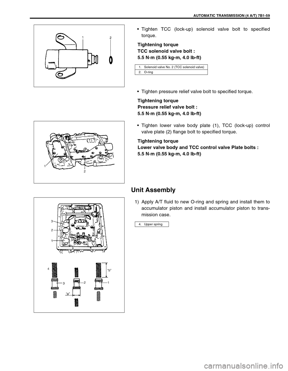
1) Apply A/T fluid to new O-ring and spring and install them to
accumulator piston and install accumulator piston to trans-
mission case.
1. Solenoid valve No. 2 (TCC solenoid valve)
2. O-ring
4. Upper spring
Page 469 of 656
7B1-60 AUTOMATIC TRANSMISSION (4 A/T)
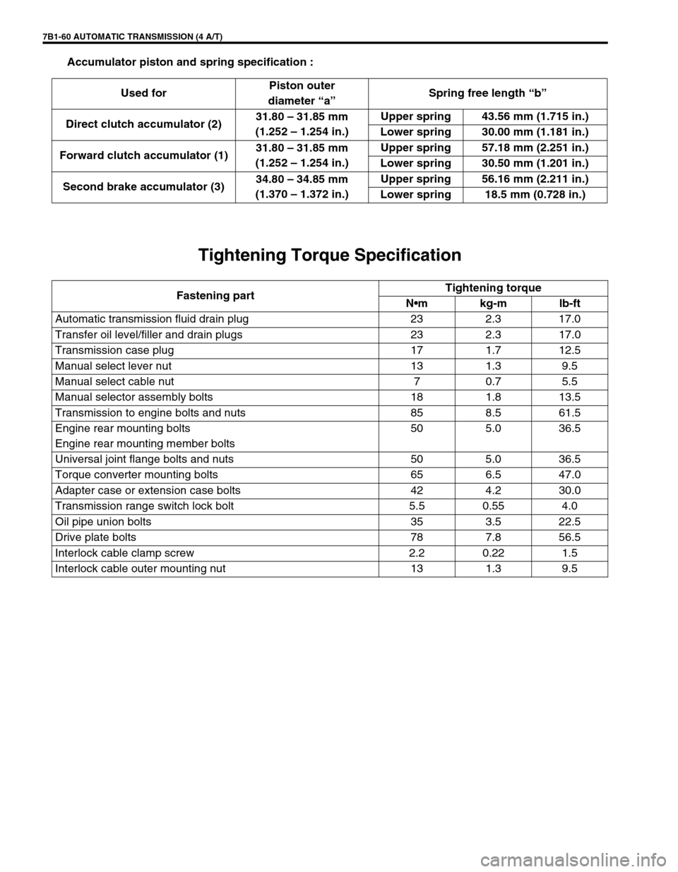
Accumulator piston and spring specification :
Tightening Torque Specification
Used forPiston outer
diameter “a”Spring free length “b”
Direct clutch accumulator (2)31.80 – 31.85 mm
(1.252 – 1.254 in.)Upper spring 43.56 mm (1.715 in.)
Lower spring 30.00 mm (1.181 in.)
Forward clutch accumulator (1)31.80 – 31.85 mm
(1.252 – 1.254 in.)Upper spring 57.18 mm (2.251 in.)
Lower spring 30.50 mm (1.201 in.)
Second brake accumulator (3)34.80 – 34.85 mm
(1.370 – 1.372 in.)Upper spring 56.16 mm (2.211 in.)
Lower spring 18.5 mm (0.728 in.)
Fastening partTightening torque
Nm kg-m lb-ft
Automatic transmission fluid drain plug 23 2.3 17.0
Transfer oil level/filler and drain plugs 23 2.3 17.0
Transmission case plug 17 1.7 12.5
Manual select lever nut 13 1.3 9.5
Manual select cable nut 7 0.7 5.5
Manual selector assembly bolts 18 1.8 13.5
Transmission to engine bolts and nuts 85 8.5 61.5
Engine rear mounting bolts
Engine rear mounting member bolts50 5.0 36.5
Universal joint flange bolts and nuts 50 5.0 36.5
Torque converter mounting bolts 65 6.5 47.0
Adapter case or extension case bolts 42 4.2 30.0
Transmission range switch lock bolt 5.5 0.55 4.0
Oil pipe union bolts 35 3.5 22.5
Drive plate bolts 78 7.8 56.5
Interlock cable clamp screw 2.2 0.22 1.5
Interlock cable outer mounting nut 13 1.3 9.5
Page:
< prev 1-8 9-16 17-24