1999 SUZUKI GRAND VITARA Evap canister
[x] Cancel search: Evap canisterPage 294 of 656

ENGINE MECHANICAL (H27 ENGINE) 6A2-7
6) Connect hoses of heater, EVAP canister, fuel feed and fuel
return.
7) Install EGR pipe with new gaskets.
8) Connect hoses of EVAP canister purge valve and heater.
9) Connect hoses of PCV, breather and water.
10) Connect couplers of manifold absolute pressure (MAP) sen-
sor, EVAP canister purge valve and EGR valve.
Fix wire harness with clamps.
11) Install clamp bracket (4) to intake collector.
12) Connect earth terminal (3) to intake collector.
13) Connect couplers of TP sensor (1) and IAC valve (2).
14) Connect brake booster hose (2) to intake manifold.
15) Connect injector wire (1) coupler.
1. Heater hose
2. Fuel feed hose
3. Fuel return hose
4. EVAP canister hose
13
2 4
1. EVAP canister purge valve 6. PCV hose
2. EGR valve 7. Water hose
3. EGR pipe 8. Breather hose
4. EVAP canister purge valve hose 9. Earth terminal coupler
5. Heater hose9
4
1 7
6
2
35
8
2
14
3
2
1
Page 314 of 656

ENGINE MECHANICAL (H27 ENGINE) 6A2-27
12) Disconnect the following electric lead wires :
•Injector wire coupler
•CMP sensor coupler
•Ignition coil couplers
•CKP sensor coupler
•MAP sensor coupler
•TP sensor (1) coupler
•IAC valve (2) coupler
•Earth wire (3) from surge tank
•EVAP canister purge valve coupler
•EGR valve coupler
•Oxygen sensor -1 and -2 couplers referring to “Exhaust Man-
ifold” in this section
•Coolant temperature sensor coupler
•Knock sensor coupler
•Generator wires
•Starter wires
•Oil pressure wire
•P/S pump wire
•Earth wire from generator bracket
•Engine block heater (if equipped)
13) Remove clamps and brackets.
14) Disconnect the following hoses :
•Heater hose from heater water pipe
•Heater hose from water outlet cap
•EVAP canister hose from canister pipe
•Brake booster vacuum hose
15) Remove EVAP canister purge valve (5).
16) Disconnect the following hoses at the location shown in the
figure :
•Fuel feed hose (1) from fuel feed pipe
•Fuel return hose from (2) fuel return pipe
17) Remove P/S pump assembly. Refer to “POWER STEERING
PUMP” in Section 3B1.
18) Remove A/C compressor assembly. Refer to “COMPRES-
SOR ASSEMBLY” in Section 1B.
19) Remove steering shaft lower assembly. Refer to “STEERING
LOWER SHAFT ASSEMBLY” in Section 3C1.
20) Raise vehicle.
21) Remove front differential housing with differential from chas-
sis if equipped. Refer to “DISMOUNTING” in Section 7E.
22) Remove exhaust No.1 pipe. Refer to “EXHAUST MANI-
FOLD” in this section.
23) Remove exhaust manifold stiffener from transmission.
4. Clamp bracket
6. EGR valve
7. Heater hose
2
14
3
75
6
Page 328 of 656

ENGINE FUEL 6C-1
6C
SECTION 6C
ENGINE FUEL
CONTENTS
General Description ....................................... 6C-1
Fuel System ................................................. 6C-1On-Vehicle Service ........................................ 6C-2
Fuel Tank ..................................................... 6C-2
Fuel Lines .................................................... 6C-5
General Description
Fuel System
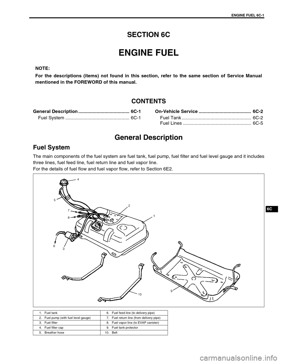
The main components of the fuel system are fuel tank, fuel pump, fuel filter and fuel level gauge and it includes
three lines, fuel feed line, fuel return line and fuel vapor line.
For the details of fuel flow and fuel vapor flow, refer to Section 6E2.NOTE:
For the descriptions (items) not found in this section, refer to the same section of Service Manual
mentioned in the FOREWORD of this manual.
1. Fuel tank 6. Fuel feed line (to delivery pipe)
2. Fuel pump (with fuel level gauge) 7. Fuel return line (from delivery pipe)
3. Fuel filter 8. Fuel vapor line (to EVAP canister)
4. Fuel filter cap 9. Fuel tank protector
5. Breather hose 10. Belt
Page 331 of 656

6C-4 ENGINE FUEL
INSTALLATION
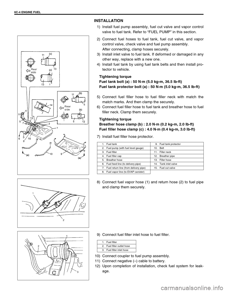
1) Install fuel pump assembly, fuel cut valve and vapor control
valve to fuel tank. Refer to “FUEL PUMP” in this section.
2) Connect fuel hoses to fuel tank, fuel cut valve, and vapor
control valve, check valve and fuel pump assembly.
After connecting, clamp hoses securely.
3) Install inlet valve to fuel tank. If deformed or damaged in any
other way, replace with a new one.
4) Install fuel tank by using fuel tank belts and then install pro-
tector to vehicle.
Tightening torque
Fuel tank bolt (a) : 50 N·m (5.0 kg-m, 36.5 lb-ft)
Fuel tank protector bolt (a) : 50 N·m (5.0 kg-m, 36.5 lb-ft)
5) Connect fuel filler hose to fuel filler neck with match the
match marks. And then clamp the securely.
6) Connect fuel filler hose to fuel tank and breather hose to fuel
filler neck. Clamp them securely.
Tightening torque
Breather hose clamp (b) : 2.0 N·m (0.2 kg-m, 2.0 lb-ft)
Fuel filler hose clamp (c) : 4.0 N·m (0.4 kg-m, 3.0 lb-ft)
7) Install fuel filler hose protector.
8) Connect fuel vapor hose (1) and return hose (2) to fuel pipe
and clamp them securely.
9) Connect fuel filter inlet hose to fuel filter.
10) Connect coupler to fuel pump assembly.
11) Connect negative (–) cable to battery.
12) Upon completion of installation, check fuel system for leak-
age.
1. Fuel tank 9. Fuel tank protector
2. Fuel pump (with fuel level gauge) 10. Belt
3. Fuel filter 11. Filler neck
4. Fuel filler cap 12. Breather pipe
5. Breather hose 13. Filler hose
6. Fuel feed line (to delivery pipe) 14. Tank inlet valve
7. Fuel return line (from delivery pipe) 15. Fuel cut valve
8. Fuel vapor line (to EVAP canister)
1. Fuel filter
2. Fuel filter outlet hose
3. Fuel filter inlet hose
Page 335 of 656

6E2-2 ENGINE AND EMISSION CONTROL SYSTEM (SEQUENTIAL MULTIPORT FUEL INJECTION FOR H27 ENGINE)
Fuel injector.......................................... 6E2-26
Electronic Control System........................ 6E2-31
Engine control module (ECM)/
powertrain control module (PCM) ........ 6E2-31
Mass air flow sensor (MAF sensor)...... 6E2-32
Intake air temperature (IAT) sensor ..... 6E2-34
Throttle position sensor (TP sensor) .... 6E2-35
Engine coolant temperature sensor
(ECT sensor) ........................................ 6E2-36
Heated oxygen sensor (sensor 1) ........ 6E2-37
Heated oxygen sensor (sensor 2) ........ 6E2-38
Vehicle speed sensor (VSS) ................ 6E2-39
Manifold absolute pressure sensor ...... 6E2-39
Fuel level sensor (sender gauge)......... 6E2-41
Crankshaft position sensor................... 6E2-41Main relay ............................................ 6E2-41
Fuel pump relay ................................... 6E2-42
Fuel cut operation ................................ 6E2-43
Emission Control System......................... 6E2-44
EGR system (if equipped) .................... 6E2-44
EVAP canister ...................................... 6E2-45
Vacuum passage ................................. 6E2-46
PCV System ............................................ 6E2-47
PCV hose ............................................. 6E2-47
PCV valve ............................................ 6E2-47
PCV system ......................................... 6E2-48
Tightening Torque Specification.............. 6E2-48
Special Tool ............................................... 6E2-48
General Description
The engine and emission control system has 4 major sub-systems: air intake system, fuel delivery system, elec-
tronic control system and emission control system.
Air intake system includes air cleaner, mass air flow sensor, throttle body, idle air control valve and intake man-
ifold.
Fuel delivery system includes fuel pump, delivery pipe, fuel pressure regulator, fuel injectors, etc.
Electronic control system includes ECM (PCM), various sensors and controlled devices.
Emission control system includes EGR, EVAP and PCV systems.
Page 338 of 656

ENGINE AND EMISSION CONTROL SYSTEM (SEQUENTIAL MULTIPORT FUEL INJECTION FOR H27 ENGINE) 6E2-5
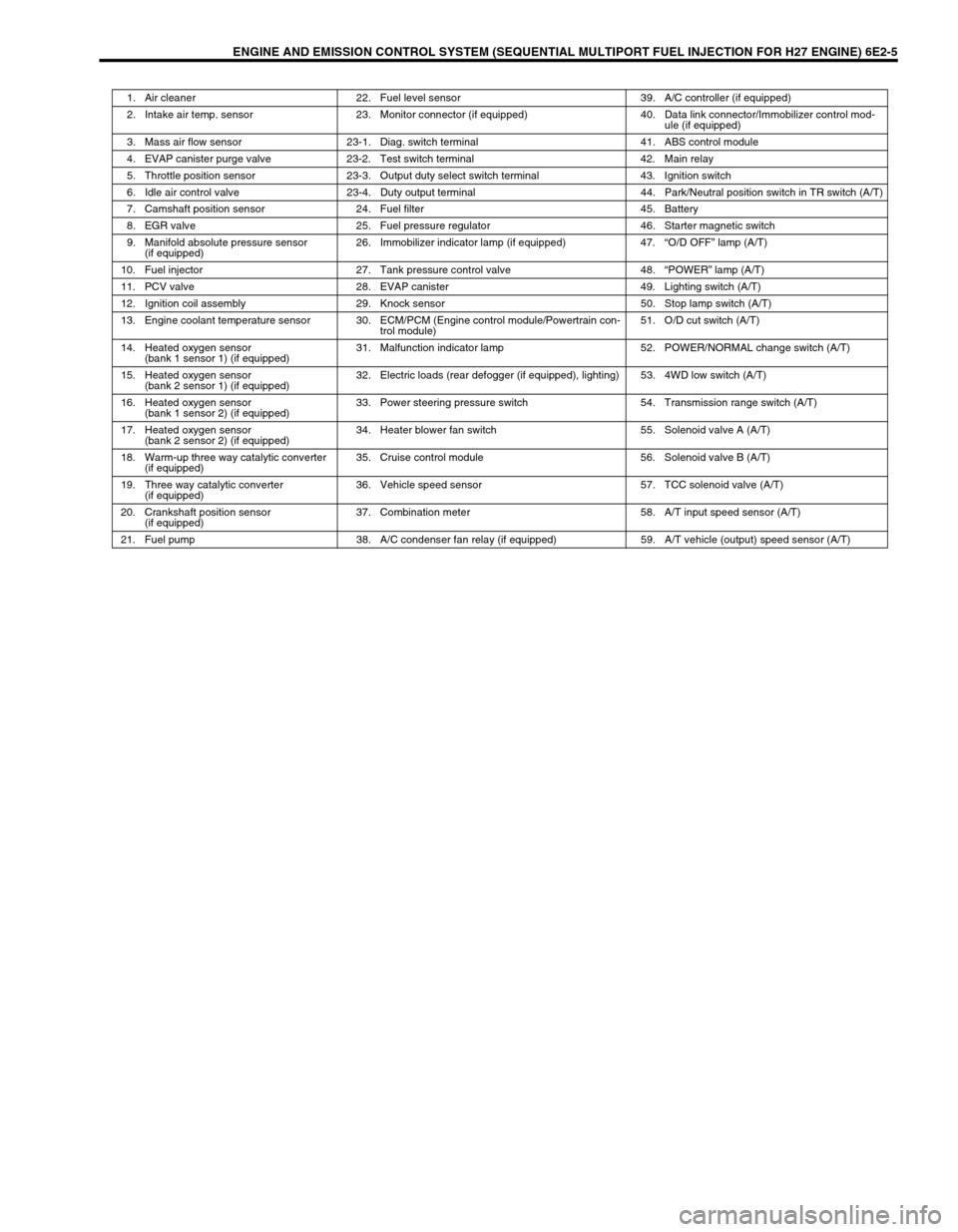
1. Air cleaner 22. Fuel level sensor 39. A/C controller (if equipped)
2. Intake air temp. sensor 23. Monitor connector (if equipped) 40. Data link connector/Immobilizer control mod-
ule (if equipped)
3. Mass air flow sensor 23-1. Diag. switch terminal 41. ABS control module
4. EVAP canister purge valve 23-2. Test switch terminal 42. Main relay
5. Throttle position sensor 23-3. Output duty select switch terminal 43. Ignition switch
6. Idle air control valve 23-4. Duty output terminal 44. Park/Neutral position switch in TR switch (A/T)
7. Camshaft position sensor 24. Fuel filter 45. Battery
8. EGR valve 25. Fuel pressure regulator 46. Starter magnetic switch
9. Manifold absolute pressure sensor
(if equipped)26. Immobilizer indicator lamp (if equipped) 47.“O/D OFF” lamp (A/T)
10. Fuel injector 27. Tank pressure control valve 48.“POWER” lamp (A/T)
11. PCV valve 28. EVAP canister 49. Lighting switch (A/T)
12. Ignition coil assembly 29. Knock sensor 50. Stop lamp switch (A/T)
13. Engine coolant temperature sensor 30. ECM/PCM (Engine control module/Powertrain con-
trol module)51. O/D cut switch (A/T)
14. Heated oxygen sensor
(bank 1 sensor 1) (if equipped)31. Malfunction indicator lamp 52. POWER/NORMAL change switch (A/T)
15. Heated oxygen sensor
(bank 2 sensor 1) (if equipped)32. Electric loads (rear defogger (if equipped), lighting) 53. 4WD low switch (A/T)
16. Heated oxygen sensor
(bank 1 sensor 2) (if equipped)33. Power steering pressure switch 54. Transmission range switch (A/T)
17. Heated oxygen sensor
(bank 2 sensor 2) (if equipped)34. Heater blower fan switch 55. Solenoid valve A (A/T)
18. Warm-up three way catalytic converter
(if equipped)35. Cruise control module 56. Solenoid valve B (A/T)
19. Three way catalytic converter
(if equipped)36. Vehicle speed sensor 57. TCC solenoid valve (A/T)
20. Crankshaft position sensor
(if equipped)37. Combination meter 58. A/T input speed sensor (A/T)
21. Fuel pump 38. A/C condenser fan relay (if equipped) 59. A/T vehicle (output) speed sensor (A/T)
Page 341 of 656

6E2-8 ENGINE AND EMISSION CONTROL SYSTEM (SEQUENTIAL MULTIPORT FUEL INJECTION FOR H27 ENGINE)
Electronic Control System
The electronic control system consists of 1) various sensors which detect the state of engine and driving condi-
tions, 2) ECM (PCM) which controls various devices according to the signals from the sensors and 3) various
controlled devices.
Functionally, it is divided into the following sub systems:
•Fuel injection control system
•Heated oxygen sensor heater control system (if equipped)
•Idle air control system
•Fuel pump control system
•Evaporative emission control system
•Ignition control system
•EGR system (if equipped)
Also, with A/T model, PCM controls A/T.
INFORMATION SENSORS CONTROLLED DEVICES OTHERS
1. IAT sensor a : A/C condenser fan motor relay (if equipped) A : Main fuse box
2. MAP sensor (if equipped) b : Ignition coil assemblies B : ECM (PCM)
3. Heated oxygen sensor (sensor 1) (if equipped) c : EVAP canister purge valve C : Data link connector
4. ECT sensor d : EGR valve (if equipped) D : Combination meter
5. TP sensor e : Idle air control valve E : Fuse box
6. MAF sensor f : Injectors F : EVAP canister
7. Camshaft position sensor (CMP sensor) g : Malfunction indicator lamp
8. ABS control module h : Fuel pump relay
9. Crankshaft position sensor (CKP sensor) (if equipped) i : Main relay
10. Power steering pressure switch (PSP switch) j : Oxygen sensor heater relay (if equipped)
11. CO adjusting resistor (if equipped)
12. Monitor connector (if equipped)
13. Transmission range switch (A/T)
14. Knock sensor
NOTE:
Above figure shows left-hand steering vehicle. For right-hand steering vehicle, parts with (*) are
installed at the side of symmetry.
Page 343 of 656

6E2-10 ENGINE AND EMISSION CONTROL SYSTEM (SEQUENTIAL MULTIPORT FUEL INJECTION FOR H27 ENGINE)
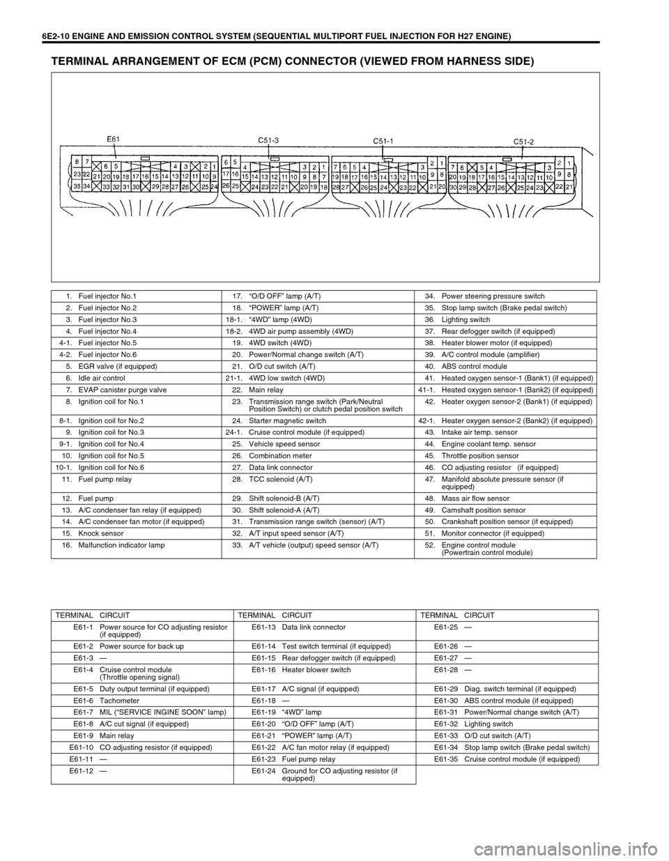
TERMINAL ARRANGEMENT OF ECM (PCM) CONNECTOR (VIEWED FROM HARNESS SIDE)
1. Fuel injector No.1 17.“O/D OFF” lamp (A/T) 34. Power steering pressure switch
2. Fuel injector No.2 18.“POWER” lamp (A/T) 35. Stop lamp switch (Brake pedal switch)
3. Fuel injector No.3 18-1.“4WD” lamp (4WD) 36. Lighting switch
4. Fuel injector No.4 18-2. 4WD air pump assembly (4WD) 37. Rear defogger switch (if equipped)
4-1. Fuel injector No.5 19. 4WD switch (4WD) 38. Heater blower motor (if equipped)
4-2. Fuel injector No.6 20. Power/Normal change switch (A/T) 39. A/C control module (amplifier)
5. EGR valve (if equipped) 21. O/D cut switch (A/T) 40. ABS control module
6. Idle air control 21-1. 4WD low switch (4WD) 41. Heated oxygen sensor-1 (Bank1) (if equipped)
7. EVAP canister purge valve 22. Main relay 41-1. Heated oxygen sensor-1 (Bank2) (if equipped)
8. Ignition coil for No.1 23. Transmission range switch (Park/Neutral
Position Switch) or clutch pedal position switch42. Heater oxygen sensor-2 (Bank1) (if equipped)
8-1. Ignition coil for No.2 24. Starter magnetic switch 42-1. Heater oxygen sensor-2 (Bank2) (if equipped)
9. Ignition coil for No.3 24-1. Cruise control module (if equipped) 43. Intake air temp. sensor
9-1. Ignition coil for No.4 25. Vehicle speed sensor 44. Engine coolant temp. sensor
10. Ignition coil for No.5 26. Combination meter 45. Throttle position sensor
10-1. Ignition coil for No.6 27. Data link connector 46. CO adjusting resistor (if equipped)
11. Fuel pump relay 28. TCC solenoid (A/T) 47. Manifold absolute pressure sensor (if
equipped)
12. Fuel pump 29. Shift solenoid-B (A/T) 48. Mass air flow sensor
13. A/C condenser fan relay (if equipped) 30. Shift solenoid-A (A/T) 49. Camshaft position sensor
14. A/C condenser fan motor (if equipped) 31. Transmission range switch (sensor) (A/T) 50. Crankshaft position sensor (if equipped)
15. Knock sensor 32. A/T input speed sensor (A/T) 51. Monitor connector (if equipped)
16. Malfunction indicator lamp 33. A/T vehicle (output) speed sensor (A/T) 52. Engine control module
(Powertrain control module)
TERMINAL CIRCUIT TERMINAL CIRCUIT TERMINAL CIRCUIT
E61-1 Power source for CO adjusting resistor
(if equipped)E61-13 Data link connector E61-25—
E61-2 Power source for back up E61-14 Test switch terminal (if equipped) E61-26—
E61-3—E61-15 Rear defogger switch (if equipped) E61-27—
E61-4 Cruise control module
(Throttle opening signal)E61-16 Heater blower switch E61-28—
E61-5 Duty output terminal (if equipped) E61-17 A/C signal (if equipped) E61-29 Diag. switch terminal (if equipped)
E61-6 Tachometer E61-18—E61-30 ABS control module (if equipped)
E61-7 MIL (“SERVICE INGINE SOON” lamp) E61-19“4WD” lamp E61-31 Power/Normal change switch (A/T)
E61-8 A/C cut signal (if equipped) E61-20“O/D OFF” lamp (A/T) E61-32 Lighting switch
E61-9 Main relay E61-21“POWER” lamp (A/T) E61-33 O/D cut switch (A/T)
E61-10 CO adjusting resistor (if equipped) E61-22 A/C fan motor relay (if equipped) E61-34 Stop lamp switch (Brake pedal switch)
E61-11—E61-23 Fuel pump relay E61-35 Cruise control module (if equipped)
E61-12—E61-24 Ground for CO adjusting resistor (if
equipped)