Page 514 of 656
![SUZUKI GRAND VITARA 1999 2.G Owners Manual INSTRUMENTATION/DRIVER INFORMATION 8C-3
COMBINATION METER INTERNAL CIRCUITS
COMBINATION METER COUPLERS
[A] : Coupler A [B] : Coupler B [C] : Coupler C
1. To Cruise control module (if equipped) GRY/YE SUZUKI GRAND VITARA 1999 2.G Owners Manual INSTRUMENTATION/DRIVER INFORMATION 8C-3
COMBINATION METER INTERNAL CIRCUITS
COMBINATION METER COUPLERS
[A] : Coupler A [B] : Coupler B [C] : Coupler C
1. To Cruise control module (if equipped) GRY/YE](/manual-img/20/7583/w960_7583-513.png)
INSTRUMENTATION/DRIVER INFORMATION 8C-3
COMBINATION METER INTERNAL CIRCUITS
COMBINATION METER COUPLERS
[A] : Coupler A [B] : Coupler B [C] : Coupler C
1. To Cruise control module (if equipped) GRY/YEL 1. To door switch (drive side) BLK/BLU 1. To ground BLK
2. Blank–2. To transmission range switch
(A/T vehicle only, if equipped) LGRN/BLU 2. To ECM (PCM for A/T vehicle) BRN
3. To ignition switch BLK/WHT 3. To transmission range switch
(A/T vehicle only, if equipped) 2GRN/ORN 3. To ignition switch PPL/RED
4. Blank–4. To transmission range switch
(A/T vehicle only, if equipped) DYEL/GRN 4. To brake fluid level switch RED/BLK
5. To ABS control module (if equipped) BLU/ORN 5. To transmission range switch
(A/T vehicle only, if equipped) NORN/BLU 5. To parking brake switch PPL
6. To PCM (A/T vehicle only) GRY/BLU 6. To transmission range switch
(A/T vehicle only, if equipped) PORN/GRN 6. To seat belt switch GRY/RED
7. To ABS control module (if equipped) BRN 7. To transmission range switch
(A/T vehicle only, if equipped) RRED 7. To generator WHT/RED
8. To VSS BLU/YEL 8. To illumination control module RED/GRN 8. To engine oil pressure switch YEL/BLK
9. To combination switch GRN/RED 9. To PCM (A/T vehicle only) WHT/BLK 9. To combination switch RED/YEL
10. To air bag SDM BLU 10. To ECT sensor YEL/WHT 10. To ignition switch BLU/RED
11. To main fuse WHT/BLU 11. To fuel level gauge BLU/WHT
12. To fuse box WHT 12. To ground BLU/YEL
13. To combination switch RED 13. To combination switch GRN/YEL
14. To immobilizer control module
(if equipped)PPL
15. To ECM (PCM for A/T vehicle) PPL/YEL
16. To ECM (PCM for A/T vehicle) ORN/BLK
P R N D 2 LCRUISEPOWER4WDSPEED
METERTACHO
METERFUEL
METERTEMP.
METER
A-11
A-13 A-8 B-12 B-11 C-8 A-15 A-6 A-1 B-9 A-16 A-14 C-7 C-1 A-10 C-3 C-4 C-5 A-7 A-5 B-8 B-1B-10 C-2 A-12 A-3B-13 B-2 B-3 B-4 B-5 B- B-6 C-9 C-10 A-9ABS circuit EBD circuit Air bag circuit
or ABS or BRAKE
if equipped
or CHECK
ENGINE
NOTE:
Terminal arrangement of coupler viewed from harness side.
Page 515 of 656
8C-4 INSTRUMENTATION/DRIVER INFORMATION
On-vehicle Service
Fuel Meter/Fuel Gauge Unit
Fuel level sensor (sender gauge)
INSPECTION
Remove fuel pump assembly referring to Section 6C.
Use an ohmmeter to confirm that resistance of sender gauge unit
changes with change of float position.
If measured value is out of specification, replace fuel sender
gauge.
Fuel level sensor specification :
Float Position Resistance (Ω
ΩΩ Ω)
“a”53.6 mm
(2.11 in.)6 – 8
“b”143.1 mm
(5.63 in.)28 – 36
“c”256.9 mm
(10.11 in.)90 – 100
1. Fuel pump assembly
2. Fuel level gauge (–) terminal
3. Fuel level gauge (+) terminal
4. Float
Page 548 of 656

BODY SERVICE 9-3
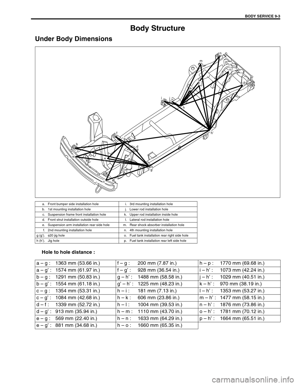
Body Structure
Under Body Dimensions
Hole to hole distance :
a. Front bumper side installation hole i. 3rd mounting installation hole
b. 1st mounting installation hole j. Lower rod installation hole
c. Suspension frame front installation hole k. Upper rod installation inside hole
d. Front strut installation outside hole l. Lateral rod installation hole
e. Suspension arm installation rear side hole m. Rear shock absorber installation hole
f. 2nd mounting installation hole n. 4th mounting installation hole
g (g’).φ
20 jig hole o. Fuel tank installation rear right side hole
h (h’). Jig hole p. Fuel tank installation rear left side hole
b
a
h’
e
f
g
d
g’
c
ij
h
o
p
n
m
l
k
a – g : 1363 mm (53.66 in.) f – g : 200 mm (7.87 in.) h – p : 1770 mm (69.68 in.)
a – g’ : 1574 mm (61.97 in.) f – g’ : 928 mm (36.54 in.) i – h’ : 1073 mm (42.24 in.)
b – g : 1291 mm (50.83 in.) g – h’ : 1488 mm (58.58 in.) j – h’ : 1029 mm (40.51 in.)
b – g’ : 1554 mm (61.18 in.) g’ – h’ : 1225 mm (48.23 in.) k – h’ : 970 mm (38.19 in.)
c – g : 1354 mm (53.31 in.) h – i : 181 mm (7.13 in.) l – h’ : 1353 mm (53.27 in.)
c – g’ : 1084 mm (42.68 in.) h – k : 606 mm (23.86 in.) m – h’ : 1477 mm (58.15 in.)
d – f : 1339 mm (52.72 in.) h – l : 1004 mm (39.53 in.) n – h’ : 1876 mm (73.86 in.)
d – g’ : 913 mm (35.94 in.) h – m : 1110 mm (43.70 in.) o – h’ : 1781 mm (70.12 in.)
e – g : 569 mm (22.40 in.) h – n : 1633 mm (64.29 in.) p – h’ : 1664 mm (65.51 in.)
e – g’ : 881 mm (34.68 in.) h – o : 1660 mm (65.35 in.)
Page 557 of 656
9-12 BODY SERVICE
1. Rear quarter inner panel 5. Roof panel 9. Air outlet panel
2. Side body outer panel 6. Front pillar upper reinforcement“A” : Apply sealant
3. Back pillar outer panel 7. Rear wheel housing panel“B” : Brush treatment
4. Front pillar inner panel 8. Fuel inlet box
N
“A” (“B”)“A” (“B”)
C
C
“A”5“A”
“A” (“B”)
“A” (“B”)
“A” (“B”)
“A”
“A” “A”2
6
4
117
82
97 2
13
O
U
V X W2“A” (“B”)
A
AB B L
L
“A”
N
C – C
B – BA – A
L – L
VIEW:W