Page 119 of 2267

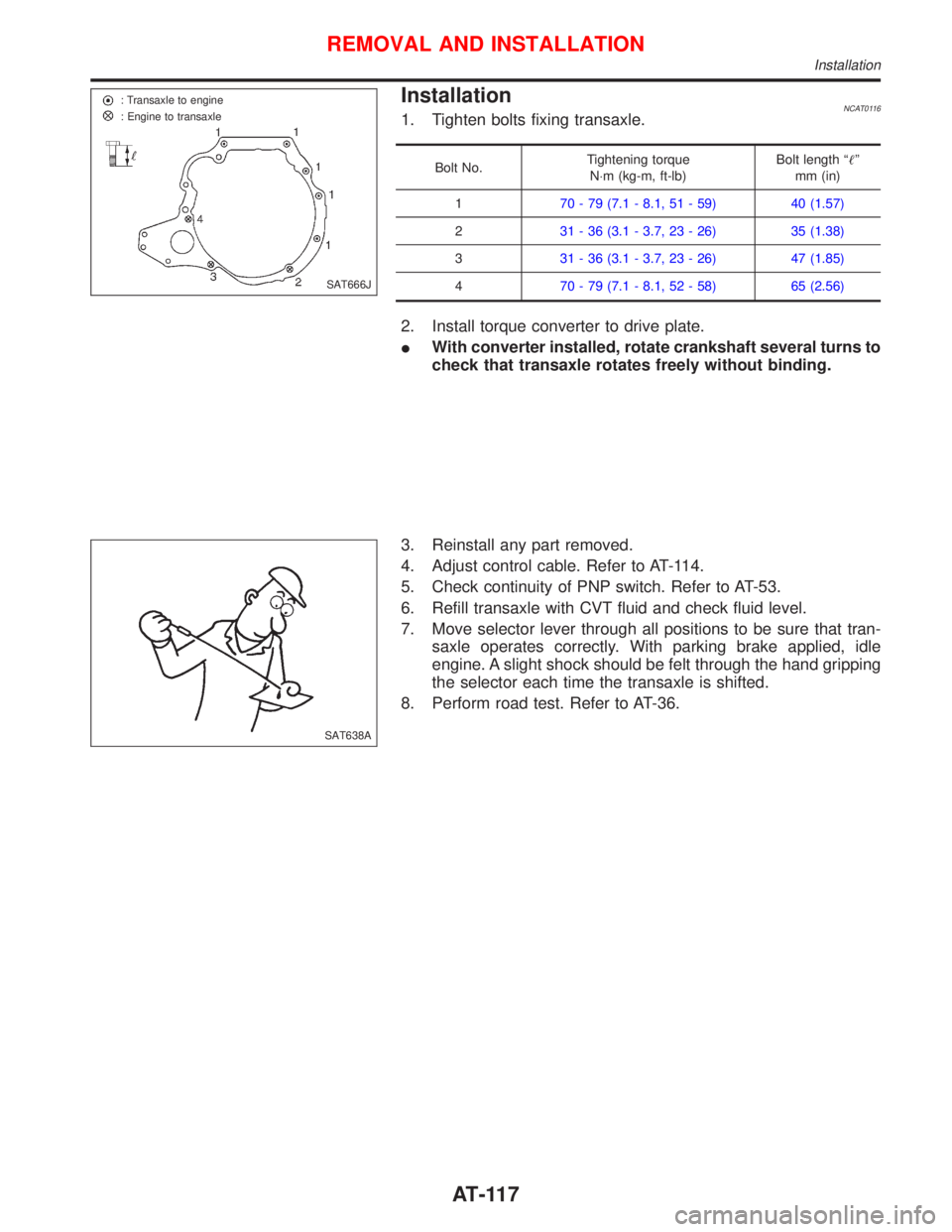
InstallationNCAT01161. Tighten bolts fixing transaxle.
Bolt No.Tightening torque
N×m (kg-m, ft-lb)Bolt length ªº
mm (in)
170 - 79 (7.1 - 8.1, 51 - 59) 40 (1.57)
231 - 36 (3.1 - 3.7, 23 - 26) 35 (1.38)
331 - 36 (3.1 - 3.7, 23 - 26) 47 (1.85)
470 - 79 (7.1 - 8.1, 52 - 58) 65 (2.56)
2. Install torque converter to drive plate.
IWith converter installed, rotate crankshaft several turns to
check that transaxle rotates freely without binding.
3. Reinstall any part removed.
4. Adjust control cable. Refer to AT-114.
5. Check continuity of PNP switch. Refer to AT-53.
6. Refill transaxle with CVT fluid and check fluid level.
7. Move selector lever through all positions to be sure that tran-
saxle operates correctly. With parking brake applied, idle
engine. A slight shock should be felt through the hand gripping
the selector each time the transaxle is shifted.
8. Perform road test. Refer to AT-36.
SAT666J : Transaxle to engine
: Engine to transaxle
SAT638A
REMOVAL AND INSTALLATION
Installation
AT-117
Page 129 of 2267

Checking Brake Fluid Level
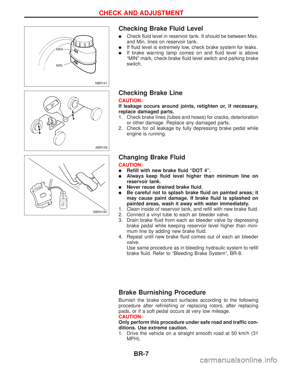
lCheck fluid level in reservoir tank. It should be between Max.
and Min. lines on reservoir tank.
lIf fluid level is extremely low, check brake system for leaks.
lIf brake warning lamp comes on and fluid level is above
ªMINº mark, check brake fluid level switch and parking brake
switch.
Checking Brake Line
CAUTION:
If leakage occurs around joints, retighten or, if necessary,
replace damaged parts.
1. Check brake lines (tubes and hoses) for cracks, deterioration
or other damage. Replace any damaged parts.
2. Check for oil leakage by fully depressing brake pedal while
engine is running.
Changing Brake Fluid
CAUTION:
lRefill with new brake fluid ªDOT 4º.
lAlways keep fluid level higher than minimum line on
reservoir tank.
lNever reuse drained brake fluid.
lBe careful not to splash brake fluid on painted areas; it
may cause paint damage. If brake fluid is splashed on
painted areas, wash it away with water immediately.
1. Clean inside of reservoir tank, and refill with new brake fluid.
2. Connect a vinyl tube to each air bleeder valve.
3. Drain brake fluid from each air bleeder valve by depressing
brake pedal while keeping reservoir level higher than mini-
mum line by adding new brake fluid.
4. Repeat until new brake fluid comes out of each air bleeder
valve.
Use same procedure as in bleeding hydraulic system to refill
brake fluid. Refer to ªBleeding Brake Systemº, BR-8.
Brake Burnishing Procedure
Burnish the brake contact surfaces according to the following
procedure after refinishing or replacing rotors, after replacing
pads, or if a soft pedal occurs at very low mileage.
CAUTION:
Only perform this procedure under safe road and traffic con-
ditions. Use extreme caution.
1. Drive the vehicle on a straight smooth road at 50 km/h (31
MPH).
NBR141 MAX.
MIN.
ABR159
SBR419C
CHECK AND ADJUSTMENT
BR-7
Page 136 of 2267
1. Loosen lock nut and adjust pedal free height by turning brake
booster input rod. Then tighten lock nut.
2. Check pedal free play.
Make sure that brake lamps go off when pedal is released.
3. Check brake pedal's depressed height while engine is run-
ning.
If depressed height is below specified value, check brake
system for leaks, accumulation of air or any damage to com-
ponents (master cylinder, wheel cylinder, etc.); then make
necessary repairs.
SBR229E Stays inside
Clevis
Lock nut
Input rod
BRAKE PEDAL AND BRACKET
Adjustment (Cont'd)
BR-14
Page 140 of 2267
On-vehicle Service
OPERATING CHECK
1. Depress brake pedal several times with engine off. After
exhausting vacuum, make sure there is no change in pedal
stroke.
2. Depress brake pedal, then start engine. If pedal goes down
slightly, operation is normal.
AIRTIGHT CHECK
1. Start engine, and stop it after one or two minutes. Depress
brake pedal several times slowly. Booster is airtight if pedal
stroke is less each time.
2. Depress brake pedal while engine is running, and stop
engine with pedal depressed. The pedal stroke should not
change after holding pedal down for30 seconds.
Removal
CAUTION:
lBe careful not to splash brake fluid on painted areas; it
may cause paint damage. If brake fluid is splashed on
painted areas, wash it away with water immediately.
lBe careful not to deform or bend brake pipes, during
removal of booster.
SBR002A
SBR365AA OK NG
Third
Second
First
NBR437
BRAKE BOOSTER
BR-18
Page 143 of 2267
Removal and Installation
CAUTION:
When installing vacuum hoses, pay attention to the follow-
ing points.
lDo not apply any oil or lubricants to vacuum hose and
check valve.
lInsert vacuum tube into vacuum hose as shown.
lInstall check valve, paying attention to its direction.
Inspection
HOSES AND CONNECTORS
Check vacuum lines, connections and check valve for air
tightness, improper attachment, chafing and deterioration.
CHECK VALVE
Check vacuum with a vacuum pump.
Connect to
booster sideVacuum should exist.
Connect to
engine sideVacuum should not exist.
SBR225B More than 24 mm
(0.94 in)
Connect hose until it contacts pro-
trusion on vacuum tube.
SBR498A Intake manifold
sideBrake booster
side
NBR385 CAUTION
Caution label
ENG.
SBR943A Booster side
Engine side
VACUUM HOSE
BR-21
Page 144 of 2267
VACUUM PUMP
1. Install vacuum gauge.
2. Run engine at 1,000 rpm or more.
3. Check vacuum.
Specified vacuum:
86.6 kPa (866 mbar, 650 mmHg, 25.59 inHg) or
more
Booster side
Engine side
Arrow indicates
engine side
SBR844B
SBR209DA Vacuum gauge
VACUUM HOSE
Inspection (Cont'd)
BR-22
Page 171 of 2267

Inspection
1. Check control lever for wear or other damage. Replace if
necessary.
2. Check wires for discontinuity or deterioration. Replace if nec-
essary.
3. Check warning lamp and switch. Replace if necessary.
4. Check parts at each connecting portion and, if found
deformed or damaged, replace the parts.
Adjustment
Before or after adjustment, pay attention to the following points.
lMake sure the toggle lever of the rear disc brakes returns to
stopper, when the parking lever is released.
lThere is no drag when parking brake lever is released.
lVehicle is unladen.
1. Adjust clearance between shoe and drum or pad and rotor
as follows:
a. Release parking brake lever and loosen adjusting nut.
b. Depress brake pedal fully at least 10 times with engine run-
ning.
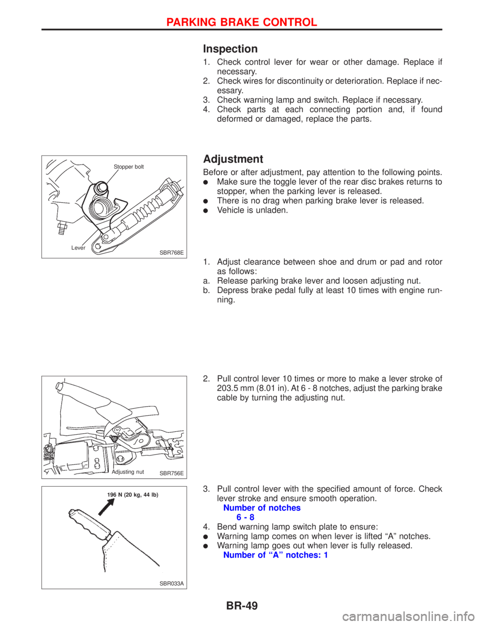
2. Pull control lever 10 times or more to make a lever stroke of
203.5 mm (8.01 in). At6-8notches, adjust the parking brake
cable by turning the adjusting nut.
3. Pull control lever with the specified amount of force. Check
lever stroke and ensure smooth operation.
Number of notches
6-8
4. Bend warning lamp switch plate to ensure:
lWarning lamp comes on when lever is lifted ªAº notches.
lWarning lamp goes out when lever is fully released.
Number of ªAº notches: 1
SBR768E Stopper bolt
Lever
SBR756E Adjusting nut
SBR033A 196 N (20 kg, 44 lb)
PARKING BRAKE CONTROL
BR-49
Page 192 of 2267

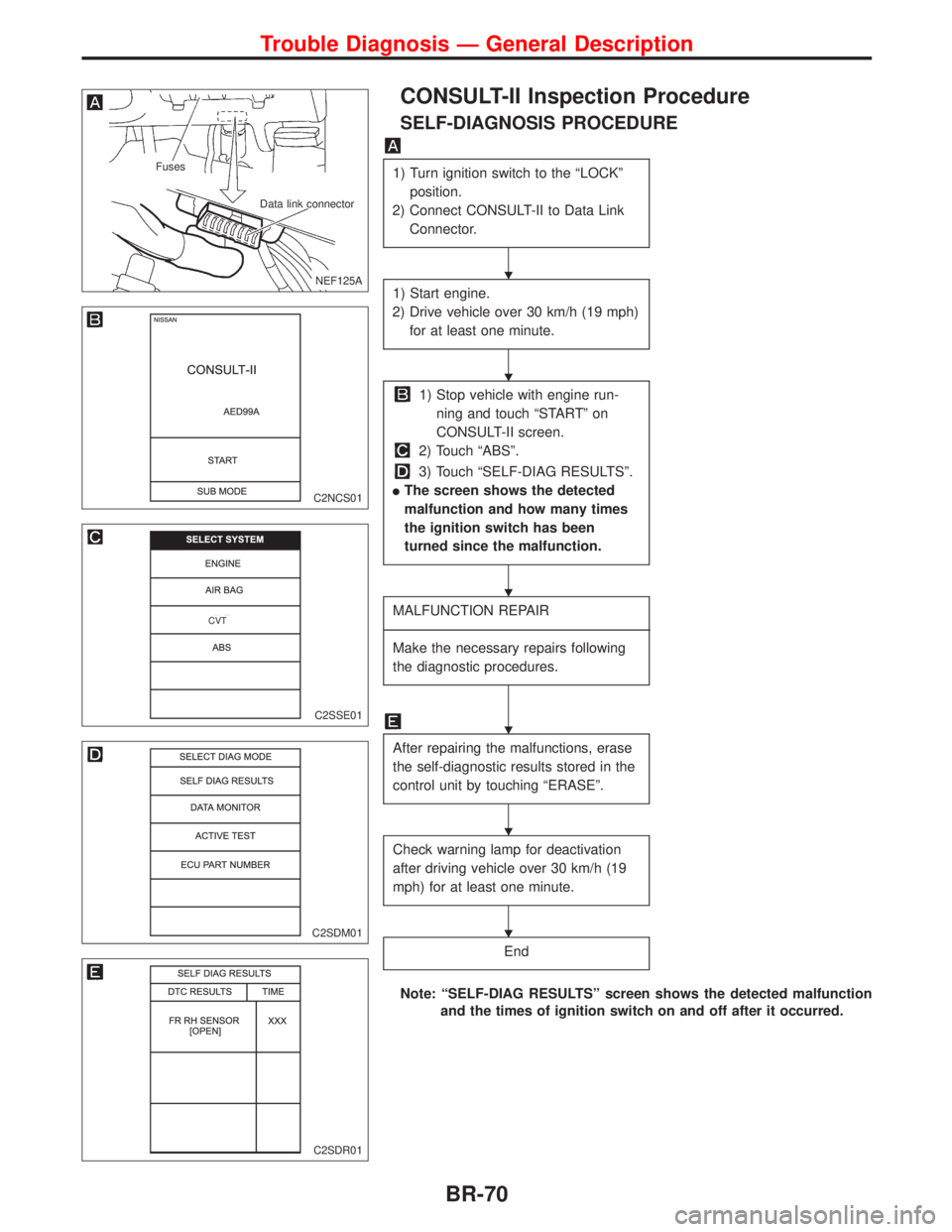
CONSULT-II Inspection Procedure
SELF-DIAGNOSIS PROCEDURE
1) Turn ignition switch to the ªLOCKº
position.
2) Connect CONSULT-II to Data Link
Connector.
1) Start engine.
2) Drive vehicle over 30 km/h (19 mph)
for at least one minute.
1) Stop vehicle with engine run-
ning and touch ªSTARTº on
CONSULT-II screen.
2) Touch ªABSº.
3) Touch ªSELF-DIAG RESULTSº.
lThe screen shows the detected
malfunction and how many times
the ignition switch has been
turned since the malfunction.
MALFUNCTION REPAIR
----------------------------------------------------------------------------------------------------------------------------------------------------------------------------------------------------------------------------------------------------------------------------------------------------------
Make the necessary repairs following
the diagnostic procedures.
After repairing the malfunctions, erase
the self-diagnostic results stored in the
control unit by touching ªERASEº.
Check warning lamp for deactivation
after driving vehicle over 30 km/h (19
mph) for at least one minute.
End
Note: ªSELF-DIAG RESULTSº screen shows the detected malfunction
and the times of ignition switch on and off after it occurred.
.NEF125A
Fuses
Data link connector
C2NCS01
C2SSE01
.CVT
C2SDM01
C2SDR01
H
H
H
H
H
H
Trouble Diagnosis Ð General Description
BR-70