Page 545 of 2267
Main Power Supply and Ground Circuit
WIRING DIAGRAMNCEC0047
YEC770
BATTERY
Refer to EL-POWER.
OFF
ACCST
ONIGNITION
SWITCH
FUSE
BLOCK
(J/B)
To EC-IGN/SG,
EC-TP/SW,
EC-AAC/V,
EC-EGR,
EC-EGVC/V ECM RELAY
: Detectable line for DTC
: Non-detectable line for DTC
Refer to last page (Foldout page) ECM
TROUBLE DIAGNOSIS FOR POWER SUPPLYQG16I18DE
Main Power Supply and Ground Circuit
EC-103
Page 546 of 2267

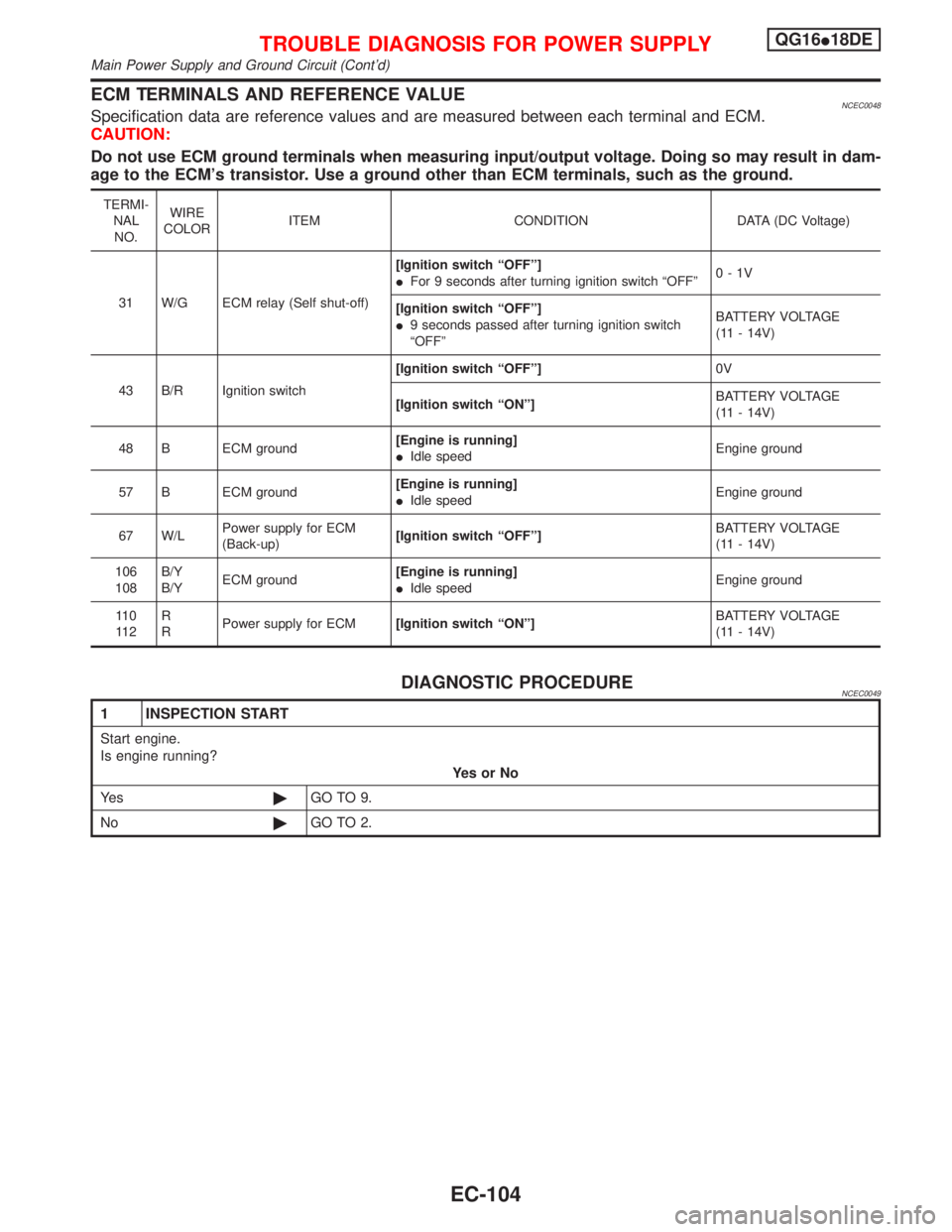
ECM TERMINALS AND REFERENCE VALUENCEC0048Specification data are reference values and are measured between each terminal and ECM.
CAUTION:
Do not use ECM ground terminals when measuring input/output voltage. Doing so may result in dam-
age to the ECM's transistor. Use a ground other than ECM terminals, such as the ground.
TERMI-
NAL
NO.WIRE
COLORITEM CONDITION DATA (DC Voltage)
31 W/G ECM relay (Self shut-off)[Ignition switch ªOFFº]
IFor 9 seconds after turning ignition switch ªOFFº0-1V
[Ignition switch ªOFFº]
I9 seconds passed after turning ignition switch
ªOFFºBATTERY VOLTAGE
(11 - 14V)
43 B/R Ignition switch[Ignition switch ªOFFº]0V
[Ignition switch ªONº]BATTERY VOLTAGE
(11 - 14V)
48 B ECM ground[Engine is running]
IIdle speedEngine ground
57 B ECM ground[Engine is running]
IIdle speedEngine ground
67 W/LPower supply for ECM
(Back-up)[Ignition switch ªOFFº]BATTERY VOLTAGE
(11 - 14V)
106
108B/Y
B/YECM ground[Engine is running]
IIdle speedEngine ground
11 0
11 2R
RPower supply for ECM[Ignition switch ªONº]BATTERY VOLTAGE
(11 - 14V)
DIAGNOSTIC PROCEDURENCEC0049
1 INSPECTION START
Start engine.
Is engine running?
YesorNo
Ye s©GO TO 9.
No©GO TO 2.
TROUBLE DIAGNOSIS FOR POWER SUPPLYQG16I18DE
Main Power Supply and Ground Circuit (Cont'd)
EC-104
Page 547 of 2267
2 CHECK POWER SUPPLY-I
1. Turn ignition switch ªOFFº and then ªONº.
2. Check voltage between ECM terminal 43 and ground with CONSULT-II or tester.
SEF981WVoltage: Battery voltage
OK or NG
OK©GO TO 9.
NG©GO TO 3.
3 DETECT MALFUNCTIONING PART
Check the following.
I10A Fuse
I40A fusible link
IHarness connectors M50, F104
IHarness for open or short between ECM and fuse block
IHarness for open or short between fuse block and ignition switch
©Repair harness or connectors.
4 CHECK ECM GROUND CIRCUIT FOR OPEN AND SHORT-I
1. Turn ignition switch ªOFFº.
2. Disconnect ECM harness connector.
3. Check harness continuity between ECM terminals 48, 57, 106, 108 and engine ground.
Refer to WIRING DIAGRAM.
Continuity should exist.
4. Also check harness for short to power.
OK or NG
OK©GO TO 5.
NG©Repair open circuit or short to power in harness or connectors.
TROUBLE DIAGNOSIS FOR POWER SUPPLYQG16I18DE
Main Power Supply and Ground Circuit (Cont'd)
EC-105
Page 548 of 2267
5 CHECK POWER SUPPLY-II
1. Disconnect ECM relay.
SEF984W
2. Check voltage between ECM relay terminals 1, 6 and ground with CONSULT-II or tester.
SEF101Y
OK or NG
OK©GO TO 7.
NG©GO TO 6.
6 DETECT MALFUNCTIONING PART
Check the following.
I10A fuse
I15A fuse
IHarness for open or short between ECM relay and battery
©Repair open circuit or short to ground or short to power in harness or connectors.
7 CHECK OUTPUT SIGNAL CIRCUIT FOR OPEN AND SHORT
1. Check harness continuity between ECM terminal 31 and ECM relay terminal 2.
Continuity should exist.
2. Also check harness for short to ground and short to power.
OK or NG
OK©Go to ªIGNITION SIGNALº, EC-QG-323.
NG©GO TO 8.
8 DETECT MALFUNCTIONING PART
Check the harness for open or short between ECM relay and ECM.
©Repair open circuit or short to ground or short to power in harness or connectors.
TROUBLE DIAGNOSIS FOR POWER SUPPLYQG16I18DE
Main Power Supply and Ground Circuit (Cont'd)
EC-106
Page 549 of 2267
9 CHECK POWER SUPPLY-II
1. Stop engine.
2. Check voltage between ECM terminals 67 and ground with CONSULT-II or tester.
SEF982WVoltage: Battery voltage
OK or NG
OK©GO TO 11.
NG©GO TO 10.
10 DETECT MALFUNCTIONING PART
Check the following.
IHarness connectors E90, F73
I10A fuse
IHarness for open or short between ECM and fuse
©Repair harness or connectors.
11 CHECK POWER SUPPLY-III
1. Turn ignition switch ªONº and then ªOFFº.
2. Check voltage between ECM terminals 110, 112 and ground with CONSULT-II or tester.
SEF983WVoltage:
After turning ignition switch ªOFFº, battery voltage will exist for a few seconds, then drop to approximately 0V.
OK or NG
OK©GO TO 17.
NG (Battery voltage does not
exist.)©GO TO 12.
NG (Battery voltage exists for
more than a few seconds.)©GO TO 16.
TROUBLE DIAGNOSIS FOR POWER SUPPLYQG16I18DE
Main Power Supply and Ground Circuit (Cont'd)
EC-107
Page 550 of 2267
12 CHECK HARNESS CONTINUITY BETWEEN ECM RELAY AND ECM
1. Disconnect ECM harness connector.
2. Disconnect ECM relay.
SEF984W3. Check harness continuity between ECM terminals 110, 112 and relay terminal 5.
Refer to wiring diagram.
Continuity should exist.
4. Also check harness for short to ground and short to power.
OK or NG
OK©GO TO 14.
NG©GO TO 13.
13 DETECT MALFUNCTIONING PART
Check the following.
IHarness connectors E90, F73
IHarness for open or short between ECM relay and ECM
©Repair open circuit or short to ground or short to power in harness or connectors.
14 CHECK VOLTAGE BETWEEN ECM RELAY AND GROUND
Check voltage between relay terminals 1, 3 and ground with CONSULT-II or tester.
SEF985WVoltage: Battery voltage
OK or NG
OK©GO TO 16.
NG©GO TO 15.
15 DETECT MALFUNCTIONING PART
Check the harness for open or short between ECM relay and fuse.
©Repair harness or connectors.
TROUBLE DIAGNOSIS FOR POWER SUPPLYQG16I18DE
Main Power Supply and Ground Circuit (Cont'd)
EC-108
Page 556 of 2267

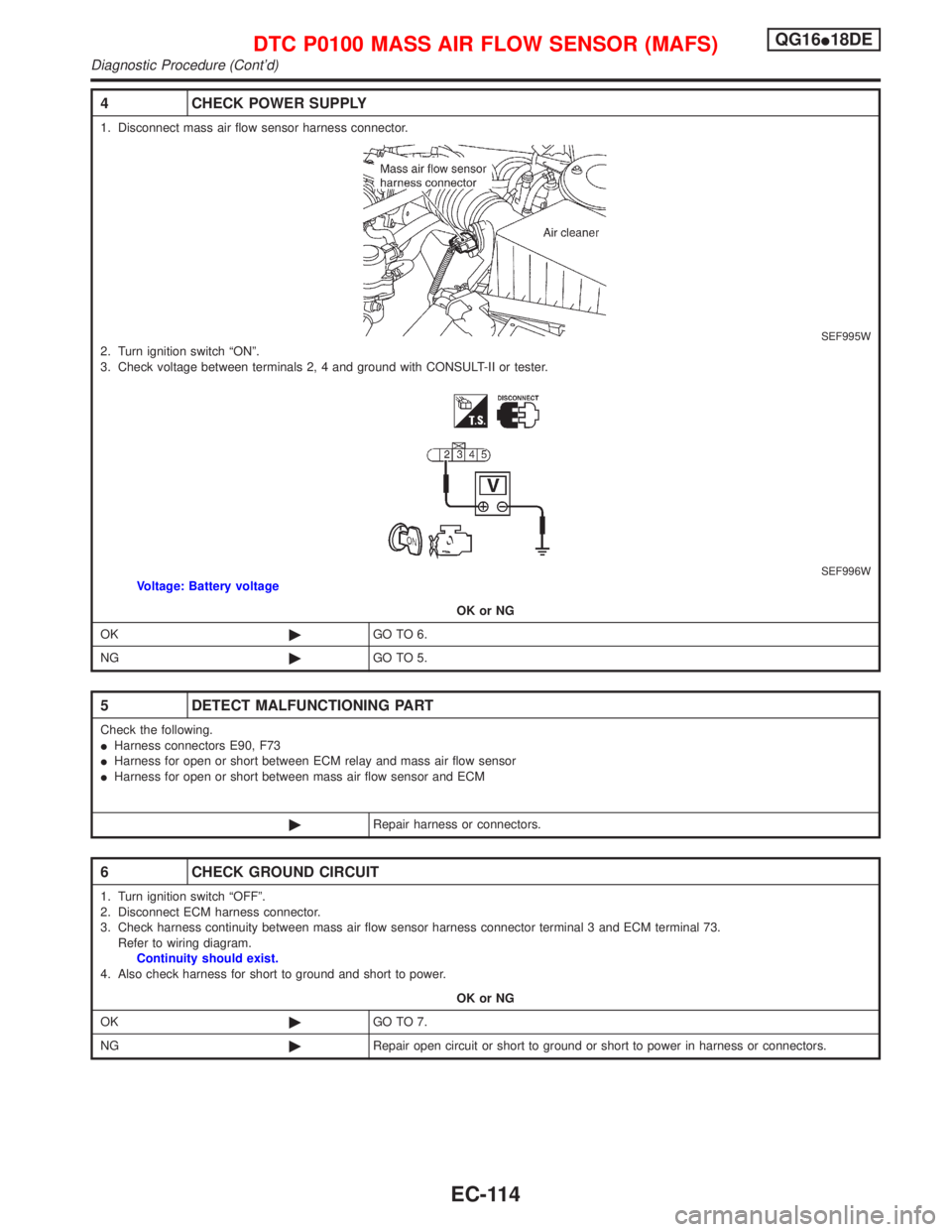
4 CHECK POWER SUPPLY
1. Disconnect mass air flow sensor harness connector.
SEF995W2. Turn ignition switch ªONº.
3. Check voltage between terminals 2, 4 and ground with CONSULT-II or tester.
SEF996WVoltage: Battery voltage
OK or NG
OK©GO TO 6.
NG©GO TO 5.
5 DETECT MALFUNCTIONING PART
Check the following.
IHarness connectors E90, F73
IHarness for open or short between ECM relay and mass air flow sensor
IHarness for open or short between mass air flow sensor and ECM
©Repair harness or connectors.
6 CHECK GROUND CIRCUIT
1. Turn ignition switch ªOFFº.
2. Disconnect ECM harness connector.
3. Check harness continuity between mass air flow sensor harness connector terminal 3 and ECM terminal 73.
Refer to wiring diagram.
Continuity should exist.
4. Also check harness for short to ground and short to power.
OK or NG
OK©GO TO 7.
NG©Repair open circuit or short to ground or short to power in harness or connectors.
DTC P0100 MASS AIR FLOW SENSOR (MAFS)QG16I18DE
Diagnostic Procedure (Cont'd)
EC-114
Page 568 of 2267

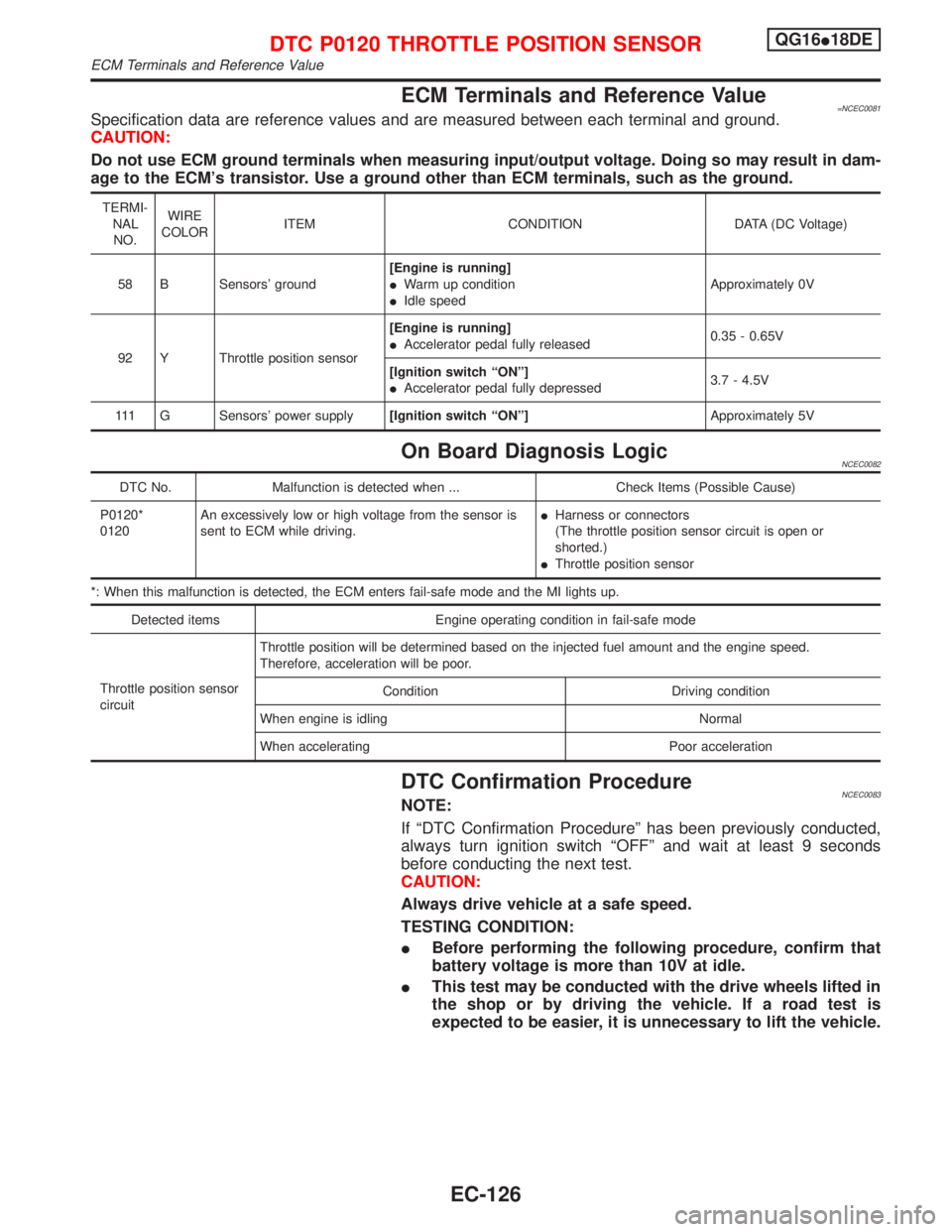
ECM Terminals and Reference Value=NCEC0081Specification data are reference values and are measured between each terminal and ground.
CAUTION:
Do not use ECM ground terminals when measuring input/output voltage. Doing so may result in dam-
age to the ECM's transistor. Use a ground other than ECM terminals, such as the ground.
TERMI-
NAL
NO.WIRE
COLORITEM CONDITION DATA (DC Voltage)
58 B Sensors' ground[Engine is running]
IWarm up condition
IIdle speedApproximately 0V
92 Y Throttle position sensor[Engine is running]
IAccelerator pedal fully released0.35 - 0.65V
[Ignition switch ªONº]
IAccelerator pedal fully depressed3.7 - 4.5V
111 G Sensors' power supply[Ignition switch ªONº]Approximately 5V
On Board Diagnosis LogicNCEC0082
DTC No. Malfunction is detected when ... Check Items (Possible Cause)
P0120*
0120An excessively low or high voltage from the sensor is
sent to ECM while driving.IHarness or connectors
(The throttle position sensor circuit is open or
shorted.)
IThrottle position sensor
*: When this malfunction is detected, the ECM enters fail-safe mode and the MI lights up.
Detected items Engine operating condition in fail-safe mode
Throttle position sensor
circuitThrottle position will be determined based on the injected fuel amount and the engine speed.
Therefore, acceleration will be poor.
Condition Driving condition
When engine is idling Normal
When accelerating Poor acceleration
DTC Confirmation ProcedureNCEC0083NOTE:
If ªDTC Confirmation Procedureº has been previously conducted,
always turn ignition switch ªOFFº and wait at least 9 seconds
before conducting the next test.
CAUTION:
Always drive vehicle at a safe speed.
TESTING CONDITION:
IBefore performing the following procedure, confirm that
battery voltage is more than 10V at idle.
IThis test may be conducted with the drive wheels lifted in
the shop or by driving the vehicle. If a road test is
expected to be easier, it is unnecessary to lift the vehicle.
DTC P0120 THROTTLE POSITION SENSORQG16I18DE
ECM Terminals and Reference Value
EC-126