1999 NISSAN PRIMERA sensor
[x] Cancel search: sensorPage 323 of 2267
![NISSAN PRIMERA 1999 Electronic Repair Manual SELF-DIAGNOSTIC MODE
Regarding items detected in ªSELF-DIAG RESULTSº mode, refer to ªDiagnostic Trouble chartº.
DATA MONITOR MODE
Monitored item
[Unit]ECM
input
signalsMain
signalsDescription Rema NISSAN PRIMERA 1999 Electronic Repair Manual SELF-DIAGNOSTIC MODE
Regarding items detected in ªSELF-DIAG RESULTSº mode, refer to ªDiagnostic Trouble chartº.
DATA MONITOR MODE
Monitored item
[Unit]ECM
input
signalsMain
signalsDescription Rema](/manual-img/5/57377/w960_57377-322.png)
SELF-DIAGNOSTIC MODE
Regarding items detected in ªSELF-DIAG RESULTSº mode, refer to ªDiagnostic Trouble chartº.
DATA MONITOR MODE
Monitored item
[Unit]ECM
input
signalsMain
signalsDescription Remarks
CKPS×RPM
(TDC) [rpm]
qq
lThe engine speed computed from the
crankshaft position sensor (TDC) sig-
nal is displayed.
CMPS×RPM -
PUMP [rpm]
qq
lThe engine speed computed from the
camshaft position sensor (PUMP) sig-
nal is displayed.
COOLAN TEMP/S
[ÉC] or [ÉF]
qq
lThe engine coolant temperature (deter-
mined by the signal voltage of the
engine coolant temperature sensor) is
displayed.lWhen the engine coolant temperature
sensor is open or short-circuited, ECM
enters fail-safe mode. The engine cool-
ant temperature determined by the
ECM is displayed.
VHCL SPEED SE
[km/h] or [mph]
qq
lThe vehicle speed computed from the
vehicle speed sensor signal or ABS
actuator and electric unit (control unit)
signal is displayed.
FUEL TEMP SEN
[ÉC] or [ÉF]
qq
lThe fuel temperature (determined by
the signal voltage of the fuel tempera-
ture sensor) is displayed.
ACCEL POS SEN
[V]
qqlThe accelerator position sensor signal
voltage is displayed.
OFF ACCEL POS
[ON/OFF]
qqlIndicates [ON/OFF] condition from the
accelerator position switch signal.
C/SLEEV POS/S [V]
qqlThe control sleeve position sensor sig-
nal voltage is displayed.
BATTERY VOLT [V]
qqlThe power supply voltage of ECM is
displayed.
START SIGNAL
[ON/OFF]
qqlIndicates [ON/OFF] condition from the
starter signal.lAfter starting the engine, [OFF] is dis-
played regardless of the starter signal.
AIR COND SIG
[ON/OFF]
qq
lIndicates [ON/OFF] condition of the air
conditioner switch as determined by
the air conditioner signal.
BRAKE SW
[ON/OFF]
qlIndicates [ON/OFF] condition of the
stio lamp switch.
BRAKE SW2
[ON/OFF]
qlIndicates [ON/OFF] condition of the
stio lamp switch 2.
IGN SW
[ON/OFF]
qqlIndicates [ON/OFF] condition from igni-
tion switch.
MAS AIR/FL SE [V]
qqlThe signal voltage of the mass air flow
sensor is displayed.lWhen the engine is stopped, a certain
value is indicated.
ACT INJ TIMG [É]
q
lThe actual injection timing angle deter-
mined by the ECM (an approximate
average angle between injection start
and end from TDC) is displayed.
TARGET F/INJ
[mm
3/STROKE]q
lThe target fuel injection quantity
(determined by the ECM according to
the input signal) is indicated.
NOTE:
Any monitored item that does not match the vehicle being diagnosed is deleted from the display automatically.
ON BOARD DIAGNOSTIC SYSTEM DESCRIPTIONCD20T
CONSULT-II (Cont'd)
EC-29
Page 325 of 2267
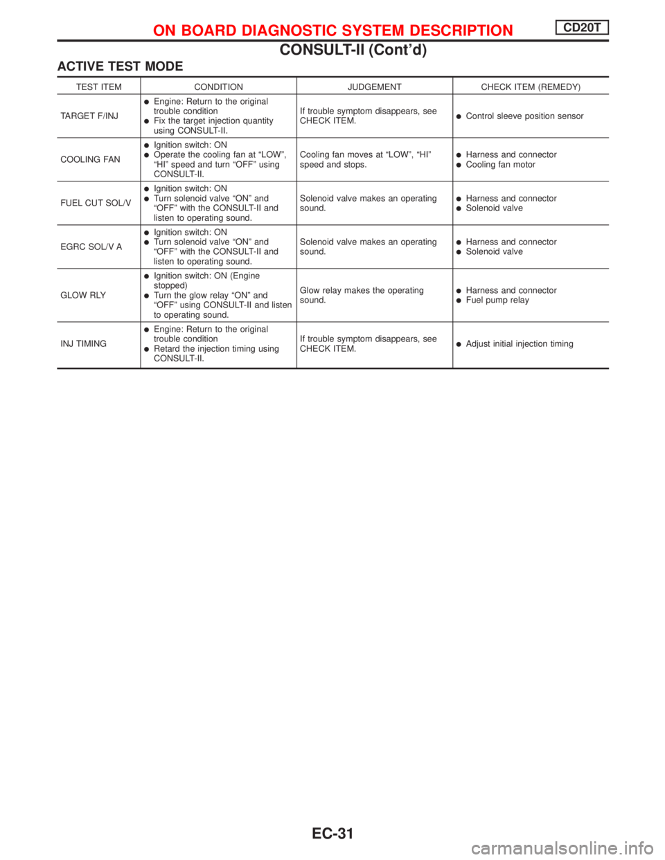
ACTIVE TEST MODE
TEST ITEM CONDITION JUDGEMENT CHECK ITEM (REMEDY)
TARGET F/INJ
lEngine: Return to the original
trouble condition
lFix the target injection quantity
using CONSULT-II.If trouble symptom disappears, see
CHECK ITEM.lControl sleeve position sensor
COOLING FAN
lIgnition switch: ONlOperate the cooling fan at ªLOWº,
ªHIº speed and turn ªOFFº using
CONSULT-II.Cooling fan moves at ªLOWº, ªHIº
speed and stops.lHarness and connectorlCooling fan motor
FUEL CUT SOL/V
lIgnition switch: ONlTurn solenoid valve ªONº and
ªOFFº with the CONSULT-II and
listen to operating sound.Solenoid valve makes an operating
sound.lHarness and connectorlSolenoid valve
EGRC SOL/V A
lIgnition switch: ONlTurn solenoid valve ªONº and
ªOFFº with the CONSULT-II and
listen to operating sound.Solenoid valve makes an operating
sound.lHarness and connectorlSolenoid valve
GLOW RLY
lIgnition switch: ON (Engine
stopped)
lTurn the glow relay ªONº and
ªOFFº using CONSULT-II and listen
to operating sound.Glow relay makes the operating
sound.lHarness and connectorlFuel pump relay
INJ TIMING
lEngine: Return to the original
trouble condition
lRetard the injection timing using
CONSULT-II.If trouble symptom disappears, see
CHECK ITEM.lAdjust initial injection timing
ON BOARD DIAGNOSTIC SYSTEM DESCRIPTIONCD20T
CONSULT-II (Cont'd)
EC-31
Page 327 of 2267
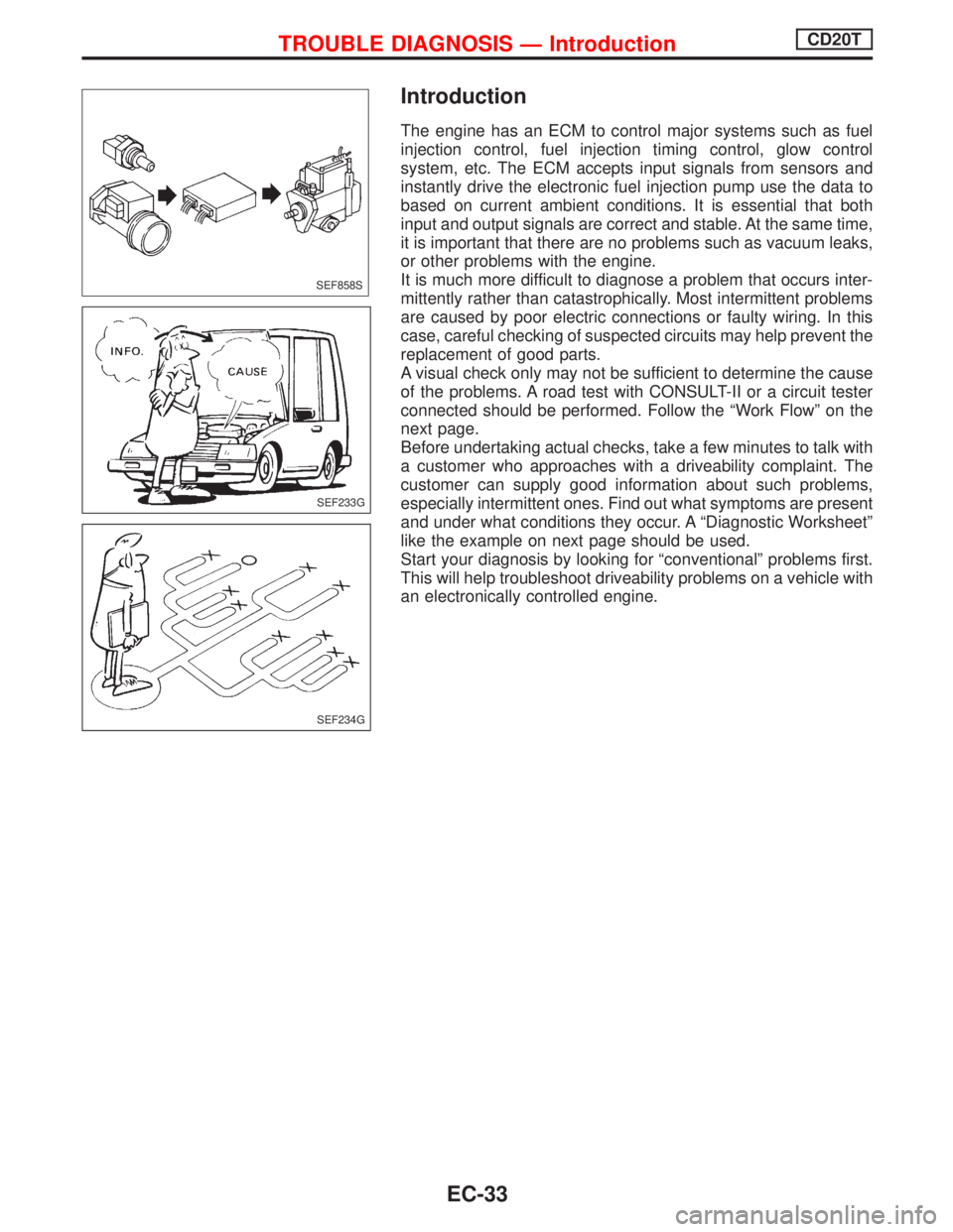
Introduction
The engine has an ECM to control major systems such as fuel
injection control, fuel injection timing control, glow control
system, etc. The ECM accepts input signals from sensors and
instantly drive the electronic fuel injection pump use the data to
based on current ambient conditions. It is essential that both
input and output signals are correct and stable. At the same time,
it is important that there are no problems such as vacuum leaks,
or other problems with the engine.
It is much more difficult to diagnose a problem that occurs inter-
mittently rather than catastrophically. Most intermittent problems
are caused by poor electric connections or faulty wiring. In this
case, careful checking of suspected circuits may help prevent the
replacement of good parts.
A visual check only may not be sufficient to determine the cause
of the problems. A road test with CONSULT-II or a circuit tester
connected should be performed. Follow the ªWork Flowº on the
next page.
Before undertaking actual checks, take a few minutes to talk with
a customer who approaches with a driveability complaint. The
customer can supply good information about such problems,
especially intermittent ones. Find out what symptoms are present
and under what conditions they occur. A ªDiagnostic Worksheetº
like the example on next page should be used.
Start your diagnosis by looking for ªconventionalº problems first.
This will help troubleshoot driveability problems on a vehicle with
an electronically controlled engine.
SEF858S
SEF233G
SEF234G
TROUBLE DIAGNOSIS Ð IntroductionCD20T
EC-33
Page 330 of 2267
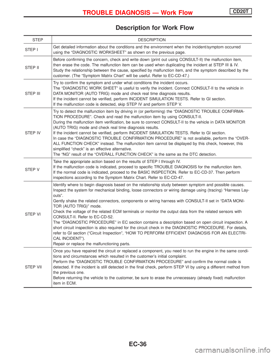
Description for Work Flow
STEP DESCRIPTION
STEP IGet detailed information about the conditions and the environment when the incident/symptom occurred
using the ªDIAGNOSTIC WORKSHEETº as shown on the previous page.
STEP IIBefore confirming the concern, check and write down (print out using CONSULT-II) the malfunction item,
then erase the code. The malfunction item can be used when duplicating the incident at STEP III & IV.
Study the relationship between the cause, specified by malfunction item, and the symptom described by the
customer. (The ªSymptom Matrix Chartº will be useful. Refer to EC-CD-47.)
STEP IIITry to confirm the symptom and under what conditions the incident occurs.
The ªDIAGNOSTIC WORK SHEETº is useful to verify the incident. Connect CONSULT-II to the vehicle in
DATA MONITOR (AUTO TRIG) mode and check real time diagnosis results.
If the incident cannot be verified, perform INCIDENT SIMULATION TESTS. Refer to GI section.
If the malfunction code is detected, skip STEP IV and perform STEP V.
STEP IVTry to detect the malfunction item by driving in (or performing) the ªDIAGNOSTIC TROUBLE CONFIRMA-
TION PROCEDUREº. Check and read the malfunction item by using CONSULT-II.
During the malfunction item verification, be sure to connect CONSULT-II to the vehicle in DATA MONITOR
(AUTO TRIG) mode and check real time diagnosis results.
If the incident cannot be verified, perform INCIDENT SIMULATION TESTS. Refer to GI section.
In case the ªDIAGNOSTIC TROUBLE CONFIRMATION PROCEDUREº is not available, perform the ªOVER-
ALL FUNCTION CHECKº instead. The malfunction item cannot be displayed by this check, however, this
simplified ªcheckº is an effective alternative.
The ªNGº result of the ªOVERALL FUNCTION CHECKº is the same as the DTC detection.
STEP VTake the appropriate action based on the results of STEP I through IV.
If the malfunction code is indicated, proceed to specific TROUBLE DIAGNOSIS for the malfunction item.
If the normal code is indicated, proceed to the BASIC INSPECTION. Refer to EC-CD-37. Then perform
inspections according to the Symptom Matrix Chart. Refer to EC-CD-47.
STEP VIIdentify where to begin diagnosis based on the relationship study between symptom and possible causes.
Inspect the system for mechanical binding, loose connectors or wiring damage using (tracing) ªHarness Lay-
outsº.
Gently shake the related connectors, components or wiring harness with CONSULT-II set in ªDATA MONI-
TOR (AUTO TRIG)º mode.
Check the voltage of the related ECM terminals or monitor the output data from the related sensors with
CONSULT-II. Refer to EC-CD-52.
The ªDIAGNOSTIC PROCEDUREº in EC section contains a description based on open circuit inspection. A
short circuit inspection is also required for the circuit check in the DIAGNOSTIC PROCEDURE. For details,
refer to GI section (ªCircuit Inspectionº, ªHOW TO PERFORM EFFICIENT DIAGNOSIS FOR AN ELECTRI-
CAL INCIDENTº).
Repair or replace the malfunctioning parts.
STEP VIIOnce you have repaired the circuit or replaced a component, you need to run the engine in the same condi-
tions and circumstances which resulted in the customer's initial complaint.
Perform the ªDIAGNOSTIC TROUBLE CONFIRMATION PROCEDUREº and confirm the normal code is
detected. If the incident is still detected in the final check, perform STEP VI by using a different method from
the previous one.
Before returning the vehicle to the customer, be sure to erase the unnecessary (already fixed) malfunction
item in ECM.
TROUBLE DIAGNOSIS Ð Work FlowCD20T
EC-36
Page 333 of 2267
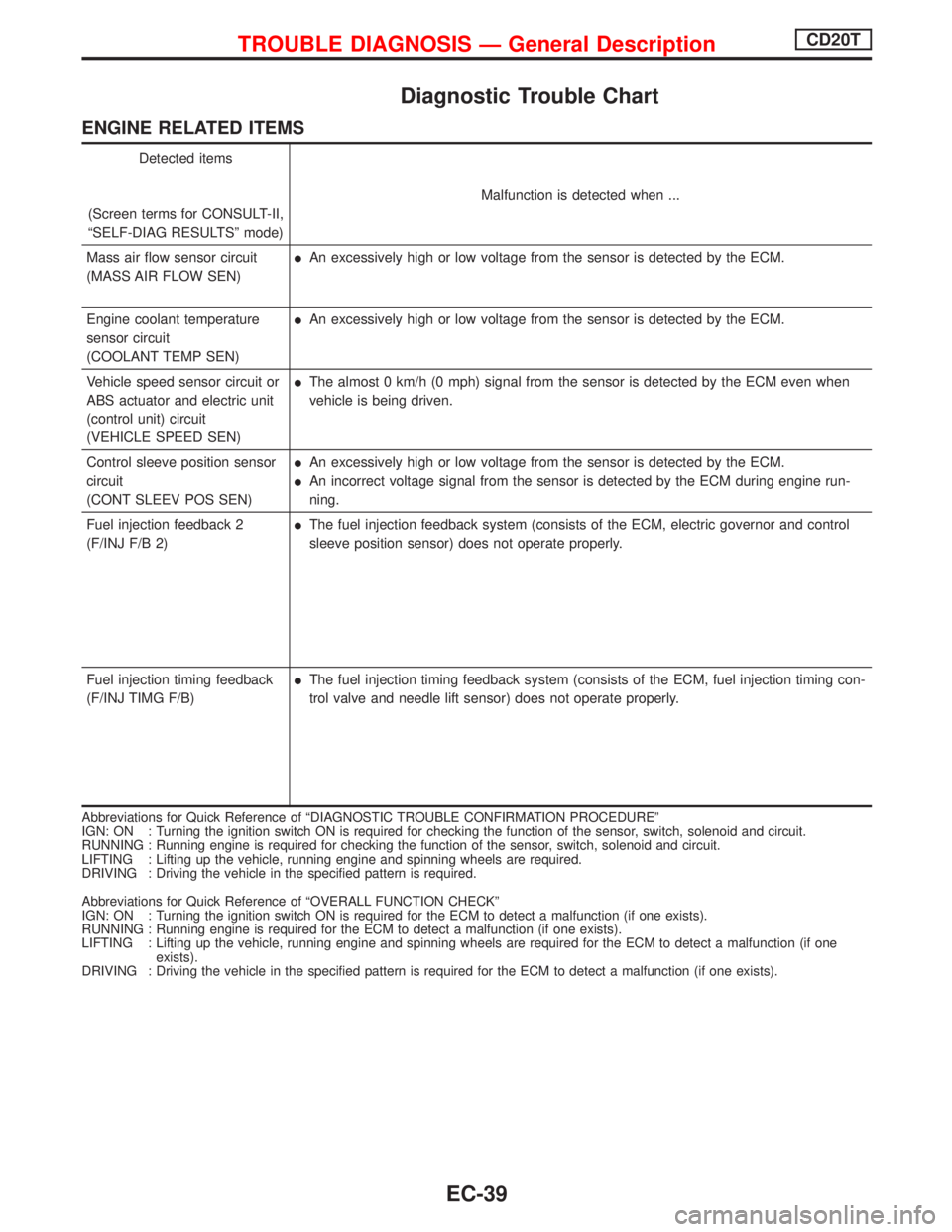
Diagnostic Trouble Chart
ENGINE RELATED ITEMS
Detected items
(Screen terms for CONSULT-II,
ªSELF-DIAG RESULTSº mode)Malfunction is detected when ...
Mass air flow sensor circuit
(MASS AIR FLOW SEN)
lAn excessively high or low voltage from the sensor is detected by the ECM.
Engine coolant temperature
sensor circuit
(COOLANT TEMP SEN)
lAn excessively high or low voltage from the sensor is detected by the ECM.
Vehicle speed sensor circuit or
ABS actuator and electric unit
(control unit) circuit
(VEHICLE SPEED SEN)
lThe almost 0 km/h (0 mph) signal from the sensor is detected by the ECM even when
vehicle is being driven.
Control sleeve position sensor
circuit
(CONT SLEEV POS SEN)
lAn excessively high or low voltage from the sensor is detected by the ECM.
lAn incorrect voltage signal from the sensor is detected by the ECM during engine run-
ning.
Fuel injection feedback 2
(F/INJ F/B 2)
lThe fuel injection feedback system (consists of the ECM, electric governor and control
sleeve position sensor) does not operate properly.
Fuel injection timing feedback
(F/INJ TIMG F/B)
lThe fuel injection timing feedback system (consists of the ECM, fuel injection timing con-
trol valve and needle lift sensor) does not operate properly.
Abbreviations for Quick Reference of ªDIAGNOSTIC TROUBLE CONFIRMATION PROCEDUREº
IGN: ON : Turning the ignition switch ON is required for checking the function of the sensor, switch, solenoid and circuit.
RUNNING : Running engine is required for checking the function of the sensor, switch, solenoid and circuit.
LIFTING : Lifting up the vehicle, running engine and spinning wheels are required.
DRIVING : Driving the vehicle in the specified pattern is required.
Abbreviations for Quick Reference of ªOVERALL FUNCTION CHECKº
IGN: ON : Turning the ignition switch ON is required for the ECM to detect a malfunction (if one exists).
RUNNING : Running engine is required for the ECM to detect a malfunction (if one exists).
LIFTING : Lifting up the vehicle, running engine and spinning wheels are required for the ECM to detect a malfunction (if one
exists).
DRIVING : Driving the vehicle in the specified pattern is required for the ECM to detect a malfunction (if one exists).
TROUBLE DIAGNOSIS Ð General DescriptionCD20T
EC-39
Page 334 of 2267
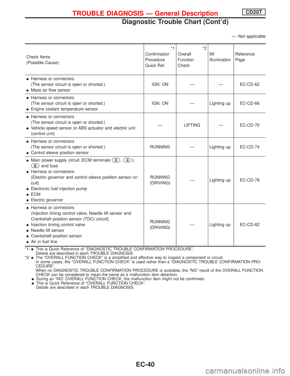
Ð: Not applicable
Check Items
(Possible Cause)*1
Confirmation
Procedure
Quick Ref.*2
Overall
Function
CheckMI
IlluminationReference
Page
lHarness or connectors
(The sensor circuit is open or shorted.)
lMass air flow sensorIGN: ON Ð Ð EC-CD-62
lHarness or connectors
(The sensor circuit is open or shorted.)
lEngine coolant temperature sensorIGN: ON Ð Lighting up EC-CD-66
lHarness or connectors
(The sensor circuit is open or shorted.)
lVehicle speed sensor or ABS actuator and electric unit
(control unit)Ð LIFTING Ð EC-CD-70
lHarness or connectors
(The sensor circuit is open or shorted.)
lControl sleeve position sensorRUNNING Ð Lighting up EC-CD-74
lMain power supply circuit (ECM terminals23,45),
68and fuse
lHarness or connectors
(Electric governor and control sleeve position sensor cir-
cuit)
lElectronic fuel injection pump
lECM
lElectric governorRUNNING
(DRIVING)Ð Lighting up EC-CD-78
lHarness or connectors
(Injection timing control valve, Needle lift sensor and
Crankshaft position sensor (TDC) circuit]
lInjection timing control valve
lNeedle lift sensor
lCrankshaft position sensor
lAir in fuel lineRUNNING
(DRIVING)Ð Lighting up EC-CD-82
*1:lThis is Quick Reference of ªDIAGNOSTIC TROUBLE CONFIRMATION PROCEDUREº.
Details are described in each TROUBLE DIAGNOSIS.
*2:
lThe ªOVERALL FUNCTION CHECKº is a simplified and effective way to inspect a component or circuit.
In some cases, the ªOVERALL FUNCTION CHECKº is used rather than a ªDIAGNOSTIC TROUBLE CONFIRMATION PRO-
CEDUREº.
When no DIAGNOSTIC TROUBLE CONFIRMATION PROCEDURE is available, the ªNGº result of the OVERALL FUNCTION
CHECK can be considered to mean the same as a malfunction item detection.
lDuring an ªNGº OVERALL FUNCTION CHECK, the malfunction item might not be confirmed.lThis is Quick Reference of ªOVERALL FUNCTION CHECKº.
Details are described in each TROUBLE DIAGNOSIS.
TROUBLE DIAGNOSIS Ð General DescriptionCD20T
Diagnostic Trouble Chart (Cont'd)
EC-40
Page 335 of 2267
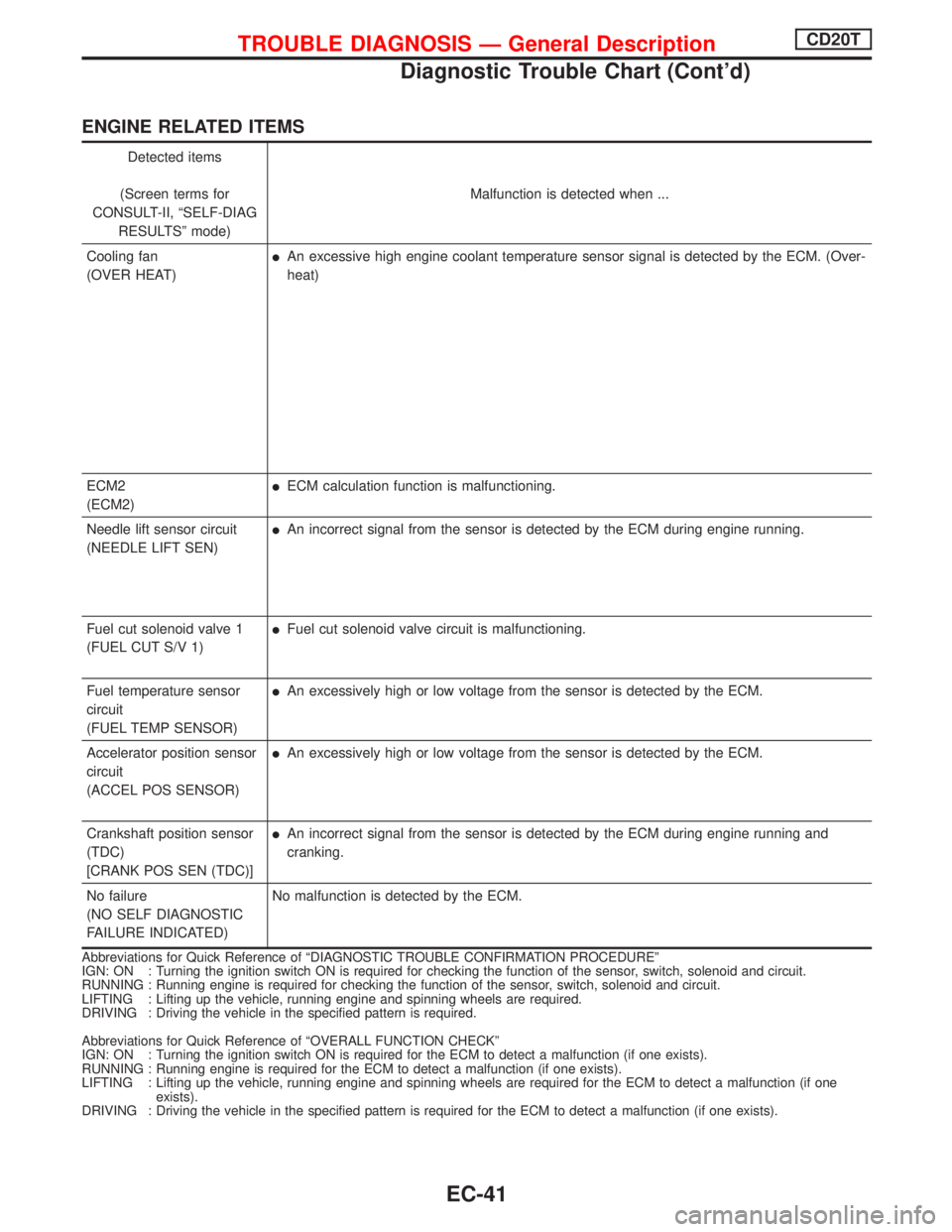
ENGINE RELATED ITEMS
Detected items
(Screen terms for
CONSULT-II, ªSELF-DIAG
RESULTSº mode)Malfunction is detected when ...
Cooling fan
(OVER HEAT)
lAn excessive high engine coolant temperature sensor signal is detected by the ECM. (Over-
heat)
ECM2
(ECM2)
lECM calculation function is malfunctioning.
Needle lift sensor circuit
(NEEDLE LIFT SEN)
lAn incorrect signal from the sensor is detected by the ECM during engine running.
Fuel cut solenoid valve 1
(FUEL CUT S/V 1)
lFuel cut solenoid valve circuit is malfunctioning.
Fuel temperature sensor
circuit
(FUEL TEMP SENSOR)
lAn excessively high or low voltage from the sensor is detected by the ECM.
Accelerator position sensor
circuit
(ACCEL POS SENSOR)
lAn excessively high or low voltage from the sensor is detected by the ECM.
Crankshaft position sensor
(TDC)
[CRANK POS SEN (TDC)]
lAn incorrect signal from the sensor is detected by the ECM during engine running and
cranking.
No failure
(NO SELF DIAGNOSTIC
FAILURE INDICATED)No malfunction is detected by the ECM.
Abbreviations for Quick Reference of ªDIAGNOSTIC TROUBLE CONFIRMATION PROCEDUREº
IGN: ON : Turning the ignition switch ON is required for checking the function of the sensor, switch, solenoid and circuit.
RUNNING : Running engine is required for checking the function of the sensor, switch, solenoid and circuit.
LIFTING : Lifting up the vehicle, running engine and spinning wheels are required.
DRIVING : Driving the vehicle in the specified pattern is required.
Abbreviations for Quick Reference of ªOVERALL FUNCTION CHECKº
IGN: ON : Turning the ignition switch ON is required for the ECM to detect a malfunction (if one exists).
RUNNING : Running engine is required for the ECM to detect a malfunction (if one exists).
LIFTING : Lifting up the vehicle, running engine and spinning wheels are required for the ECM to detect a malfunction (if one
exists).
DRIVING : Driving the vehicle in the specified pattern is required for the ECM to detect a malfunction (if one exists).
TROUBLE DIAGNOSIS Ð General DescriptionCD20T
Diagnostic Trouble Chart (Cont'd)
EC-41
Page 336 of 2267
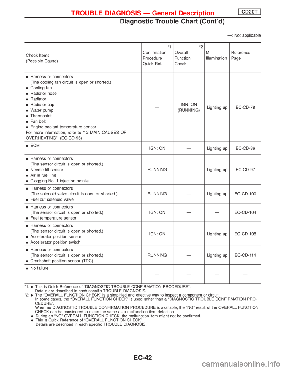
Ð: Not applicable
Check Items
(Possible Cause)*1
Confirmation
Procedure
Quick Ref.*2
Overall
Function
CheckMI
IlluminationReference
Page
lHarness or connectors
(The cooling fan circuit is open or shorted.)
lCooling fan
lRadiator hose
lRadiator
lRadiator cap
lWater pump
lThermostat
lFan belt
lEngine coolant temperature sensor
For more information, refer to ª12 MAIN CAUSES OF
OVERHEATINGº. (EC-CD-95)ÐIGN: ON
(RUNNING)Lighting up EC-CD-78
lECM
IGN: ON Ð Lighting up EC-CD-86
lHarness or connectors
(The sensor circuit is open or shorted.)
lNeedle lift sensor
lAir in fuel line
lClogging No. 1 injection nozzleRUNNING Ð Lighting up EC-CD-97
lHarness or connectors
(The solenoid valve circuit is open or shorted.)
lFuel cut solenoid valveRUNNING Ð Lighting up EC-CD-100
lHarness or connectors
(The sensor circuit is open or shorted.)
lFuel temperature sensorIGN: ON Ð Ð EC-CD-104
lHarness or connectors
(The sensor circuit is open or shorted.)
lAccelerator position sensor
lAccelerator position switchIGN: ON Ð Lighting up EC-CD-108
lHarness or connectors
(The sensor circuit is open or shorted.)
lCrankshaft position sensor (TDC)RUNNING Ð Lighting up EC-CD-114
lNo failure
Ð ÐÐÐ
*1:lThis is Quick Reference of ªDIAGNOSTIC TROUBLE CONFIRMATION PROCEDUREº.
Details are described in each specific TROUBLE DIAGNOSIS.
*2:
lThe ªOVERALL FUNCTION CHECKº is a simplified and effective way to inspect a component or circuit.
In some cases, the ªOVERALL FUNCTION CHECKº is used rather than a ªDIAGNOSTIC TROUBLE CONFIRMATION PRO-
CEDUREº.
When no DIAGNOSTIC TROUBLE CONFIRMATION PROCEDURE is available, the ªNGº result of the OVERALL FUNCTION
CHECK can be considered to mean the same as a malfunction item detection.
lDuring an ªNGº OVERALL FUNCTION CHECK, the malfunction item might not be confirmed.lThis is Quick Reference of ªOVERALL FUNCTION CHECKº.
Details are described in each specific TROUBLE DIAGNOSIS.
TROUBLE DIAGNOSIS Ð General DescriptionCD20T
Diagnostic Trouble Chart (Cont'd)
EC-42