Page 53 of 208
Press the left control to decrease
the time displayed.
AUXILIARY POWER POINT
The auxiliary power point is located
under the instrument panel. This
outlet should be used in place of the
cigarette lighter for optional
electrical accessories.
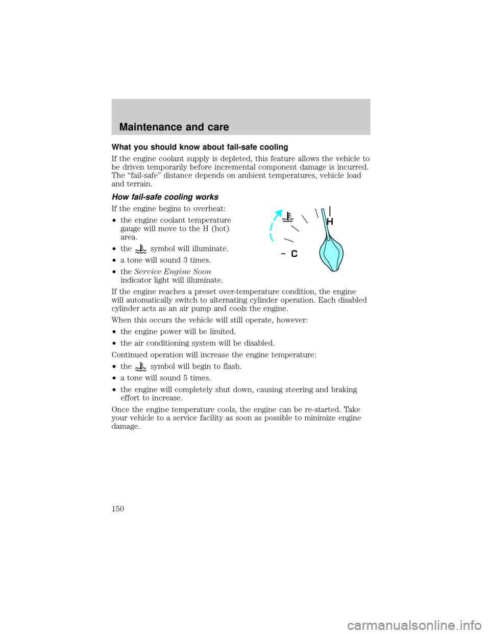
POSITIONS OF THE IGNITION
1. ACCESSORY, allows the electrical
accessories such as the radio to
operate while the engine is not
running.
2. LOCK, locks the steering wheel,
automatic transmission gearshift
lever and allows key removal.
3. OFF, shuts off the engine and all
accessories without locking the
steering wheel.
4. ON, all electrical circuits operational. Warning lights illuminated. Key
position when driving.
5. START, cranks the engine. Release the key as soon as the engine
starts.
VOL
PUSH ONTAPE
MUTESEEK
TUNE
AM
FM
REW
FFSIDE 1 2
COMP
SHUFFCDEJ
RDS
SCAN AUTO123
4
56
BASS
TREBSELBAL
FADE
EXT
OFFMAX
A/CAUTOFRONT
REARSELECTRESET
3
1
2
5
4
Controls and features
53
Page 113 of 208

STEERING
Your vehicle is equipped with power steering. Power steering uses energy
from the engine to help steer the vehicle.
To prevent damage to the power steering pump:
²Never hold the steering wheel to the extreme right or the extreme left
for more than a few seconds when the engine is running.
²Do not operate the vehicle with a low power steering pump fluid level.
If the power steering system breaks down (or if the engine is turned
off), you can steer the vehicle manually, but it takes more effort.
If the steering wanders or pulls, the condition could be caused by any of
the following:
²underinflated tire(s) on any wheel(s)
²high crown in center of road
²high crosswinds
²wheels out of alignment
²loose or worn components in steering linkage
Speed sensitive steering
The steering in your vehicle is speed sensitive. At high speeds, steering
assist will decrease to improve steering feel. At lower speeds,
maneuverability will be increased.
If the amount of effort required to steer your vehicle changes at a
constant vehicle speed, have the power steering system checked by your
dealer or a qualified service technician.
AIR SUSPENSION SYSTEM
The air suspension system is designed to improve ride, handling and
general vehicle performance during:
²certain road conditions
²steering maneuvers
²braking
²accelerations
This system keeps the rear of your vehicle at a constant level by
automatically adding air or releasing air from the springs.
Driving
113
Page 130 of 208
Fuse/Relay
LocationFuse Amp
RatingDescription
12 30A** Air Suspension
13 15A* Charging System
14 20A* Fuel Pump
15 Ð NOT USED
16 30A* Heated Seats
17 10A* Air Suspension
18 15A* Horn
19 30A* Subwoofer, I/P Fuse Panel, Fuse 33
20 15A* Fuel Injectors
21 15A* Heated Oxygen Sensors, Transmission
Solenoids, EVAP Canaster Vent Solenoid,
EGR Vacuum Regulator, EVAP Vapor
Management Valve
22 Ð Not Used
23 Ð Not Used
24 20A* Auxiliary Power Outlet
25 30A** Power Lumbar, Passenger Power Seat
26 30A CB Cooling Fan-Low Speed
27 Ð Not Used
Relay 1 Ð Fuel Pump Relay
Relay 2 Ð A/C Clutch Relay
Relay 3 Ð PCM Power Relay
Relay 4 Ð Air Suspension Relay
Relay 5 Ð Rear Defrost Relay
* Mini Fuses ** Maxi Fuses
CHANGING THE TIRES
If you get a flat tire while driving, do not apply the brake heavily.
Instead, gradually decrease your speed. Hold the steering wheel firmly
and slowly move to a safe place on the side of the road.
Roadside emergencies
130
Page 143 of 208
IDENTIFYING COMPONENTS IN THE ENGINE COMPARTMENT
4.6L SOHC V8 engine
1. Brake fluid reservoir
2. Engine oil dipstick
3. Engine oil filler cap
4. Air filter assembly
5. Power steering fluid reservoir
6. Engine coolant reservoir
7. Battery
8. Windshield washer fluid reservoir
9. Automatic transmission fluid dipstick
89123
6547
Maintenance and care
143
Page 150 of 208

What you should know about fail-safe cooling
If the engine coolant supply is depleted, this feature allows the vehicle to
be driven temporarily before incremental component damage is incurred.
The ªfail-safeº distance depends on ambient temperatures, vehicle load
and terrain.
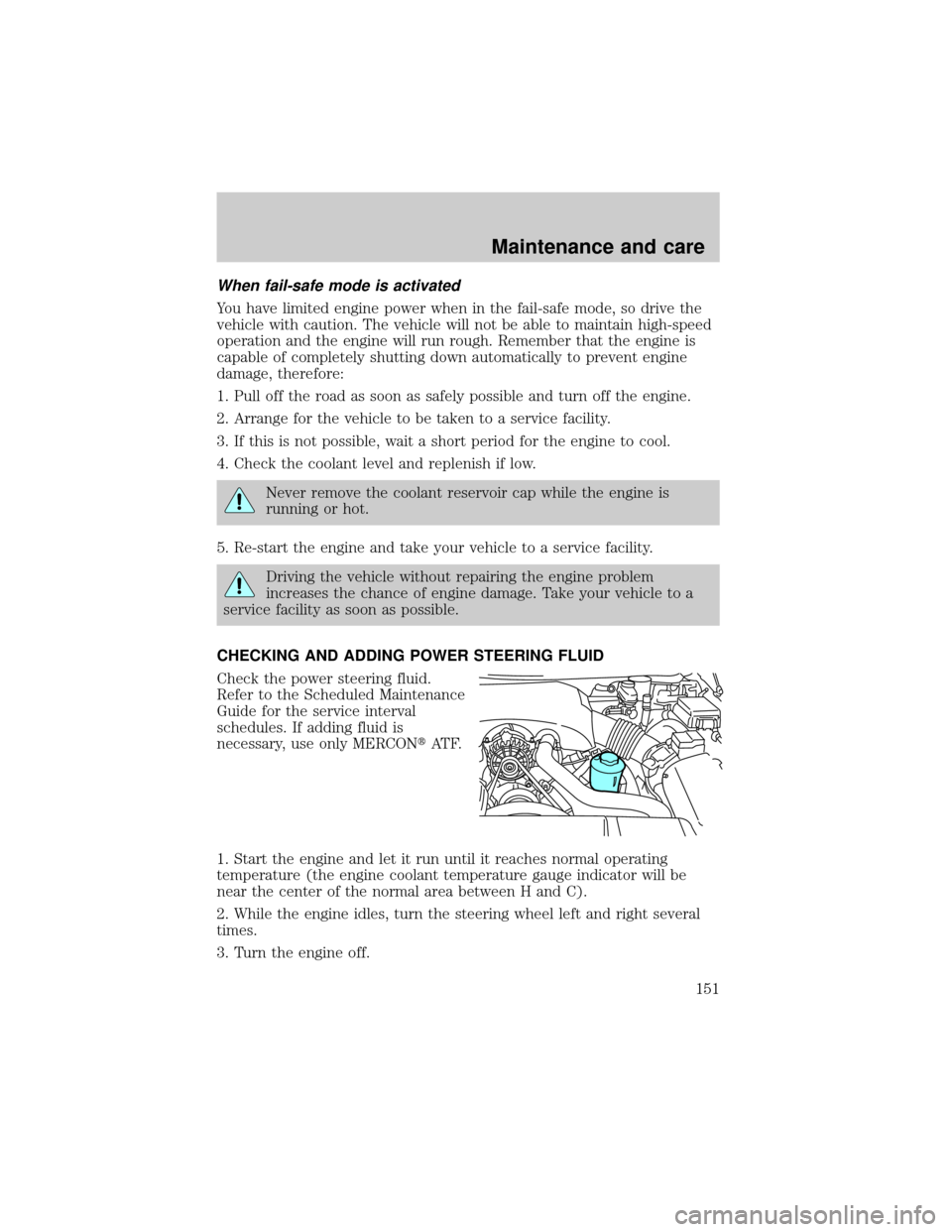
How fail-safe cooling works
If the engine begins to overheat:
²the engine coolant temperature
gauge will move to the H (hot)
area.
²the
symbol will illuminate.
²a tone will sound 3 times.
²theService Engine Soon
indicator light will illuminate.
If the engine reaches a preset over-temperature condition, the engine
will automatically switch to alternating cylinder operation. Each disabled
cylinder acts as an air pump and cools the engine.
When this occurs the vehicle will still operate, however:
²the engine power will be limited.
²the air conditioning system will be disabled.
Continued operation will increase the engine temperature:
²the
symbol will begin to flash.
²a tone will sound 5 times.
²the engine will completely shut down, causing steering and braking
effort to increase.
Once the engine temperature cools, the engine can be re-started. Take
your vehicle to a service facility as soon as possible to minimize engine
damage.
H
Maintenance and care
150
Page 151 of 208

When fail-safe mode is activated
You have limited engine power when in the fail-safe mode, so drive the
vehicle with caution. The vehicle will not be able to maintain high-speed
operation and the engine will run rough. Remember that the engine is
capable of completely shutting down automatically to prevent engine
damage, therefore:
1. Pull off the road as soon as safely possible and turn off the engine.
2. Arrange for the vehicle to be taken to a service facility.
3. If this is not possible, wait a short period for the engine to cool.
4. Check the coolant level and replenish if low.
Never remove the coolant reservoir cap while the engine is
running or hot.
5. Re-start the engine and take your vehicle to a service facility.
Driving the vehicle without repairing the engine problem
increases the chance of engine damage. Take your vehicle to a
service facility as soon as possible.
CHECKING AND ADDING POWER STEERING FLUID
Check the power steering fluid.
Refer to the Scheduled Maintenance
Guide for the service interval
schedules. If adding fluid is
necessary, use only MERCONtAT F.
1. Start the engine and let it run until it reaches normal operating
temperature (the engine coolant temperature gauge indicator will be
near the center of the normal area between H and C).
2. While the engine idles, turn the steering wheel left and right several
times.
3. Turn the engine off.
Maintenance and care
151
Page 152 of 208

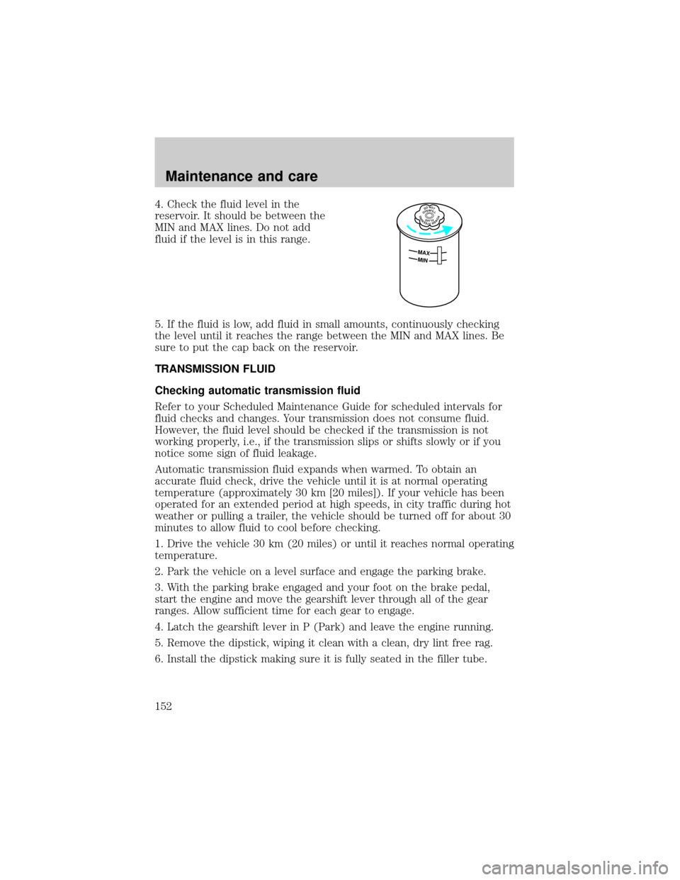
4. Check the fluid level in the
reservoir. It should be between the
MIN and MAX lines. Do not add
fluid if the level is in this range.
5. If the fluid is low, add fluid in small amounts, continuously checking
the level until it reaches the range between the MIN and MAX lines. Be
sure to put the cap back on the reservoir.
TRANSMISSION FLUID
Checking automatic transmission fluid
Refer to your Scheduled Maintenance Guide for scheduled intervals for
fluid checks and changes. Your transmission does not consume fluid.
However, the fluid level should be checked if the transmission is not
working properly, i.e., if the transmission slips or shifts slowly or if you
notice some sign of fluid leakage.
Automatic transmission fluid expands when warmed. To obtain an
accurate fluid check, drive the vehicle until it is at normal operating
temperature (approximately 30 km [20 miles]). If your vehicle has been
operated for an extended period at high speeds, in city traffic during hot
weather or pulling a trailer, the vehicle should be turned off for about 30
minutes to allow fluid to cool before checking.
1. Drive the vehicle 30 km (20 miles) or until it reaches normal operating
temperature.
2. Park the vehicle on a level surface and engage the parking brake.
3. With the parking brake engaged and your foot on the brake pedal,
start the engine and move the gearshift lever through all of the gear
ranges. Allow sufficient time for each gear to engage.
4. Latch the gearshift lever in P (Park) and leave the engine running.
5. Remove the dipstick, wiping it clean with a clean, dry lint free rag.
6. Install the dipstick making sure it is fully seated in the filler tube.DONOTOVERFILLPOWERSTEERINGFLUID
MAX
MIN
Maintenance and care
152
Page 181 of 208

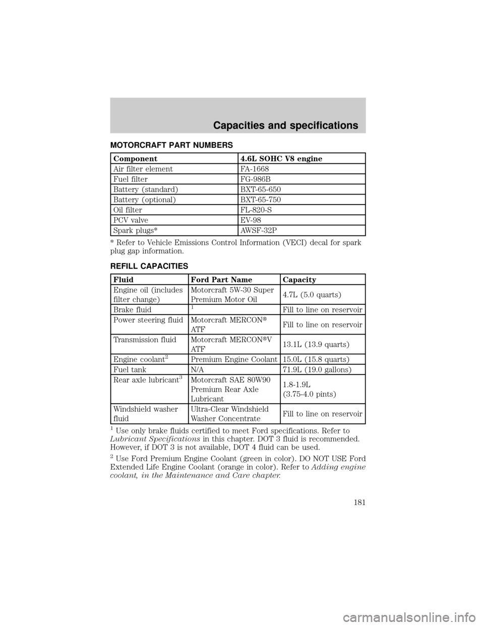
MOTORCRAFT PART NUMBERS
Component 4.6L SOHC V8 engine
Air filter element FA-1668
Fuel filter FG-986B
Battery (standard) BXT-65-650
Battery (optional) BXT-65-750
Oil filter FL-820-S
PCV valve EV-98
Spark plugs* AWSF-32P
* Refer to Vehicle Emissions Control Information (VECI) decal for spark
plug gap information.
REFILL CAPACITIES
Fluid Ford Part Name Capacity
Engine oil (includes
filter change)Motorcraft 5W-30 Super
Premium Motor Oil4.7L (5.0 quarts)
Brake fluid
1Fill to line on reservoir
Power steering fluid Motorcraft MERCONt
AT FFill to line on reservoir
Transmission fluid Motorcraft MERCONtV
AT F13.1L (13.9 quarts)
Engine coolant
2Premium Engine Coolant 15.0L (15.8 quarts)
Fuel tank N/A 71.9L (19.0 gallons)
Rear axle lubricant
3Motorcraft SAE 80W90
Premium Rear Axle
Lubricant1.8-1.9L
(3.75-4.0 pints)
Windshield washer
fluidUltra-Clear Windshield
Washer ConcentrateFill to line on reservoir
1Use only brake fluids certified to meet Ford specifications. Refer to
Lubricant Specificationsin this chapter. DOT 3 fluid is recommended.
However, if DOT 3 is not available, DOT 4 fluid can be used.
2Use Ford Premium Engine Coolant (green in color). DO NOT USE Ford
Extended Life Engine Coolant (orange in color). Refer toAdding engine
coolant, in the Maintenance and Care chapter.
Capacities and specifications
181