1999 LINCOLN CONTINENTAL warning light
[x] Cancel search: warning lightPage 59 of 208

Activation and deactivation
When either of the two Lincoln RESCU controls are pressed, or the air
bags are deployed (this will activate the system as an emergency
automatically), a warning light, located in the overhead console, will
begin to flash and status messages will be displayed on the vehicle's
message center, confirming an assistance request has been made. The
warning light will continue to flash throughout the activation.
The system can be activated whenever your ignition key is in the
RUN/START position and for six minutes after your vehicle is turned off.
Once a RESCU control has been pressed, do not attempt to crank the
engine as this may cancel the activation. In most situations, the
assistance request can only be terminated and the system reset when a
special tone is sent to the vehicle by the Lincoln Security Response
Center. (SeeAutomatic rediallater in this chapter for exceptions.)
Operation will continue even if the vehicle is turned off during an
activation (although visual feedback via the message center will not be
available in this situation).
INFO activations can be cancelled by pressing the END button on the
cellular phone.
Cellular phone interface
The cellular phone must be connected to the vehicle and activated for
the system to work. During an activation, Lincoln RESCU takes control
of the vehicle's cellular phone. If the phone is in use, the call will be
terminated and the Lincoln Security Response Center will automatically
be dialed. The cellular handset becomes inoperative and all voice
communication with the operator is accomplished via the cellular phone's
ªhands-freeº microphone.
When an activation is terminated, your phone is left unlocked, in the ON
state and may not return to its previous call restriction or system
selection setting. It can be reprogrammed to your previous setting as
desired.
Refer to your cellular phone user's manual for further information.
Controls and features
59
Page 100 of 208

Safety belt warning light and indicator chime
The seat belt warning light illuminates in the instrument cluster and a
chime sounds to remind the occupants to fasten their safety belts.
Conditions of operation
If... Then...
The driver's safety belt is not
buckled before the ignition switch
is turned to the ON position...The safety belt warning light
illuminates for one to two minutes
and the warning chime sounds for
four to eight seconds.
The driver's safety belt is buckled
while the indicator light is
illuminated and the warning chime
is sounding...The safety belt warning light and
warning chime turn off.
The driver's safety belt is buckled
before the ignition switch is turned
to the ON position...The safety belt warning light and
indicator chime remain off.
Safety belt maintenance
Inspect the safety belt systems periodically to make sure they work
properly and are not damaged. Inspect the safety belts to make sure
there are no nicks, wears or cuts, replacing if necessary. All safety belt
assemblies, including retractors, buckles, front seat belt buckle
assemblies (slide bar)(if equipped), shoulder belt height adjusters (if
equipped), child safety seat tether bracket assemblies (if equipped), and
attaching hardware, should be inspected after a collision. Ford
recommends that all safety belt assemblies used in vehicles involved in a
collision be replaced. However, if the collision was minor and a qualified
technician finds that the belts do not show damage and continue to
operate properly, they do not need to be replaced. Safety belt assemblies
not in use during a collision should also be inspected and replaced if
either damage or improper operation is noted.
Failure to inspect and if necessary replace the safety belt
assembly under the above conditions could result in severe
personal injuries in the event of a collision.
Refer toCleaning and maintaining the safety beltsin the
Maintenance and caresection.
Seating and safety restraints
100
Page 104 of 208

While the system is designed to help reduce serious injuries, it may also
cause minor burns, abrasions, swelling or temporary hearing loss.
Because air bags must inflate rapidly and with considerable force, there
is the risk of death or serious injuries such as fractures, facial and eye
injuries or internal injuries, particularly to occupants who are not
properly restrained or are otherwise out of position at the time of air bag
deployment. Thus, it is extremely important that occupants be properly
restrained as far away from the air bag module as possible while
maintaining vehicle control.
Several air bag system components get hot after inflation. Do not
touch them after inflation.
If the air bag is deployed,the air bag will not function again
and must be replaced immediately.If the air bag is not
replaced, the unrepaired area will increase the risk of injury in a
collision.
The SRS consists of:
²driver and passenger air bag modules (which include the inflators and
air bags),
²one or more impact and safing sensors,
²a readiness light and tone
²and the electrical wiring which connects the components.
The diagnostic module monitors its own internal circuits and the
supplemental air bag electrical system warning (including the impact
sensors), the system wiring, the air bag system readiness light, the air
bag back up power and the air bag ignitors.
Seating and safety restraints
104
Page 106 of 208

How does the side air bag system work?
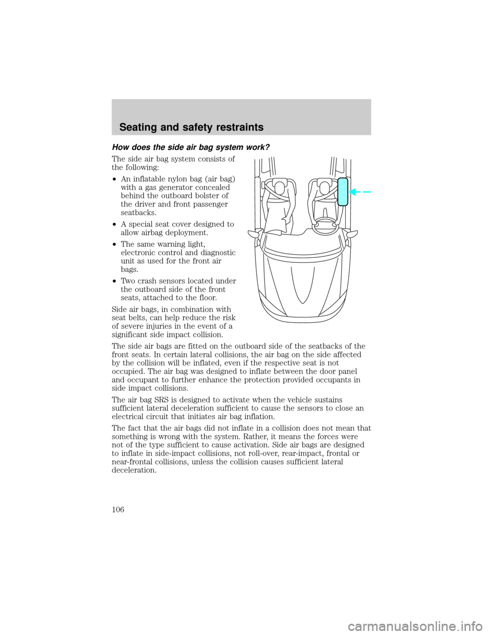
The side air bag system consists of
the following:
²An inflatable nylon bag (air bag)
with a gas generator concealed
behind the outboard bolster of
the driver and front passenger
seatbacks.
²A special seat cover designed to
allow airbag deployment.
²The same warning light,
electronic control and diagnostic
unit as used for the front air
bags.
²Two crash sensors located under
the outboard side of the front
seats, attached to the floor.
Side air bags, in combination with
seat belts, can help reduce the risk
of severe injuries in the event of a
significant side impact collision.
The side air bags are fitted on the outboard side of the seatbacks of the
front seats. In certain lateral collisions, the air bag on the side affected
by the collision will be inflated, even if the respective seat is not
occupied. The air bag was designed to inflate between the door panel
and occupant to further enhance the protection provided occupants in
side impact collisions.
The air bag SRS is designed to activate when the vehicle sustains
sufficient lateral deceleration sufficient to cause the sensors to close an
electrical circuit that initiates air bag inflation.
The fact that the air bags did not inflate in a collision does not mean that
something is wrong with the system. Rather, it means the forces were
not of the type sufficient to cause activation. Side air bags are designed
to inflate in side-impact collisions, not roll-over, rear-impact, frontal or
near-frontal collisions, unless the collision causes sufficient lateral
deceleration.
Seating and safety restraints
106
Page 120 of 208

BRAKES
Your service brakes are self-adjusting. Refer to the maintenance guide
and or service guide for scheduled maintenance.
Occasional brake noise is normal and often does not indicate a
performance concern with the vehicle's brake system. In normal
operation, automotive brake systems may emit occasional or intermittent
squeal or groan noises when the brakes are applied. Such noises are
usually heard during the first few brake applications in the morning;
however, they may be heard at any time while braking and can be
aggravated by environmental conditions such as cold, heat, moisture,
road dust, salt or mud. If a ªmetal-to-metal,º ªcontinuous grindingº or
ªcontinuous squealº sound is present while braking, the brake linings
may be worn-out and should be inspected by a qualified service
technician.
Anti-lock brake system (ABS)
On vehicles equipped with an anti-lock braking system (ABS), a noise
from the hydraulic pump motor and pulsation in the pedal may be
observed during ABS braking events. Pedal pulsation coupled with noise
while braking under panic conditions or on loose gravel, bumps, wet or
snowy roads is normal and indicates proper functioning of the vehicle's
anti-lock brake system. The ABS performs a self-check at 17 km/h (10
mph) after you start the engine and begin to drive away. A brief
mechanical noise may be heard during this test. This is normal. If a
malfunction is found, the ABS warning light will come on. If the vehicle
has continuous vibration or shudder in the steering wheel while braking,
the vehicle should be inspected by a qualified service technician.
The ABS operates by detecting the
onset of wheel lockup during brake
applications and compensating for
this tendency. The wheels are
prevented from locking even when
the brakes are firmly applied. The
accompanying illustration depicts
the advantage of an ABS equipped
vehicle (on bottom) to a non-ABS
equipped vehicle (on top) during
hard braking with loss of front braking traction.
Driving
120
Page 121 of 208

ABS warning lamp
The
ABSwarning lamp in the instrument cluster momentarily illuminates
when the ignition is turned on and the engine is off. If the light does not
illuminate momentarily at start up, remains on or continues to flash, the
ABS needs to be serviced.
With the ABS light on, the anti-lock
brake system is disabled and normal
braking is still effective unless the
brake warning light also remains
illuminated with parking brake
released. (If your brake warning lamp illuminates, have your vehicle
serviced immediately).
Using ABS
²In an emergency or when maximum efficiency from the ABS is
required, apply continuous full force on the brake. The ABS will be
activated immediately, thus allowing you to retain full steering control
of your vehicle and, providing there is sufficient space, will enable you
to avoid obstacles and bring the vehicle to a controlled stop.
²The Anti-Lock system does not decrease the time necessary to apply
the brakes or always reduce stopping distance. Always leave enough
room between your vehicle and the vehicle in front of you to stop.
²We recommend that you familiarize yourself with this braking
technique. However, avoid taking any unnecessary risks.
Parking brake with auto-release
Apply the parking brake whenever
the vehicle is parked.
To set the parking brake:
1. Move the gearshift to P (Park).
2. Push pedal downward.
The BRAKE warning lamp in the
instrument cluster illuminates and
remains illuminated (when the
ignition is turned ON) until the parking brake is fully released.
P!
BRAKE
BRAKE RELEASEHOOD
Driving
121
Page 126 of 208

If your vehicle gets stuck in mud or snow it may be rocked out by
shifting from forward and reverse gears in a steady pattern. Press lightly
on the accelerator in each gear. Do not rock the vehicle for more than a
few minutes, because it could damage the vehicle.
Always set the parking brake fully and make sure the gearshift is
latched in P (Park). Turn off the ignition whenever you leave
your vehicle.
If the parking brake is fully released, but the brake warning lamp
remains illuminated, the brakes may not be working properly.
See your dealer or a qualified service technician.
Driving with a 4±speed automatic transaxle
Your automatic overdrive transaxle provides fully automatic operation in
either D (Overdrive) or 3 (Third). Driving with the shift selector in D
(Overdrive) gives the best fuel economy for normal driving conditions.
For manual control start in 1 (First) and then shift manually.
To put your vehicle in gear, start the engine, depress the brake pedal,
then move gearshift out of P (Park).
Hold the brake pedal down while you move the gearshift lever
from P (Park) to another position. If you do not hold the brake
pedal down, your vehicle may move unexpectedly and injure someone.
Driving
126
Page 139 of 208

Fuse/Relay
LocationFuse Amp
RatingDescription
12 10A Lighting Control Module
13 15A Lighting Control Module (LCM): RF Turn
Lamp, Right Turn Indicator (VIC), RR Side
Marker Lamps, Tail Lamps, License Lamps,
LR Stop/Turn Lamps, Clock Illumination
14 20A Cigar Lighter
15 10A ABS Evac and Fill Connector
16 30A Moonroof Switch
17 Ð Not Used
18 10A Lighting Control Module
19 10A Lighting Control Module (LCM): Left
Headlamp, DRL
20 15A Multi-Function Switch: Flash to Pass, and
Hazard Warning Input to LCM
21 Ð Not Used
22 ÐÐ Not Used
23 10A Digital Transmission Range Sensor
24 10A Virtual Image Cluster-LF Turn Indicator, LF
Turn Signal
25 10A Lighting Control Module (LCM): Right
Headlamp
26 10A Virtual Image Instrument Cluster, EATC
Module
27 Ð Not Used
28 10A Shift Lock Actuator, Vehicle Dynamic Module,
Virtual Image Instrument Cluster, Rear
Window Defrost, Heated Seat Switch
Assembly, Low Tire Pressure Module, RESCU
29 10A Radio
30 10A Heated Mirrors
Roadside emergencies
139