1999 LAND ROVER DISCOVERY fuel pump
[x] Cancel search: fuel pumpPage 410 of 1529

FUEL DELIVERY SYSTEM - V8
REPAIRS 19-2-13
REPAIRS
Switch - inertia - fuel cut-off
$% 19.22.09
Remove
1.Disconnect multiplug from fuel cut-off switch.
2.Remove 2 screws securing fuel cut-off switch to
bulkhead.
3.Remove fuel cut-off switch from bulkhead.
Refit
1.Position fuel cut-off switch to bulkhead and
secure with screws.
2.Connect multiplug to fuel cut-off switch.
3.To set the fuel cut-off switch, depress the top of
the fuel cut-off switch.
Pump - fuel
$% 19.45.08
NOTE: The fuel pump and fuel gauge tank unit are
integral parts of the fuel pump housing and cannot be
renewed separately
Remove
1.Release fixings and remove battery cover.
2.Disconnect battery earth lead.
3. Models with third row seats: Remove RH
third row seat.
+ SEATS, REPAIRS, Seat - third row.
4. Remove right hand rear lower quarter trim
casing.
+ INTERIOR TRIM COMPONENTS,
REPAIRS, Trim casing - side - loadspace.
5. Models with third row seats: Remove 4
screws securing third row seat latch finishers to
body and finishers.
6.Release and remove screw cover from rear
floor carpet finisher.
7.Remove 6 screws securing loadspace carpet
finisher, remove finisher.
8.Release carpet and tie aside.
Page 411 of 1529

FUEL DELIVERY SYSTEM - V8
19-2-14 REPAIRS
9.Remove 6 screws securing fuel pump access
panel to floor.
10.Remove access panel.
11.Clean fuel pump hose connections.
12.Position absorbent cloth to absorb fuel spillage.
13.Disconnect multiplug and fuel hose from fuel
pump housing.
CAUTION: Always fit plugs to open
connections to prevent contamination.
14. NAS models: Disconnect pressure sensor
pipe from fuel pump housing.
CAUTION: Always fit plugs to open
connections to prevent contamination.
15.Use LRT-19-009 to remove locking ring from
fuel pump housing.
16.Remove fuel pump and discard sealing ring. Refit
1.Clean fuel pump housing and mating face on
fuel tank.
2.Fit new seal to mating face on fuel tank.
3.Fit fuel pump assembly to fuel tank and use
LRT-19-009 to fit locking ring.
4.Connect multiplug and fuel hose to fuel pump
housing.
5. NAS models: Connect pressure sensor pipe to
fuel pump housing.
6.Fit fuel pump access panel and secure with
screws.
7.Reposition carpet.
8.Fit carpet finisher and secure with screws.
9.Fit screw cover.
10. Models with third row seats: Fit and secure
third row seat latch finishers.
11.Fit right hand rear lower quarter trim casing.
+ INTERIOR TRIM COMPONENTS,
REPAIRS, Trim casing - side - loadspace.
12. Models with third row seats: Fit RH third row
seat.
+ SEATS, REPAIRS, Seat - third row.
13.Connect battery earth lead.
14.Fit battery cover and secure with fixings.
Page 424 of 1529

COOLING SYSTEM - V8
DESCRIPTION AND OPERATION 26-2-9
Viscous fan
1Coolant pump pulley drive attachment
2Fan blades3Bi-metallic coil
4Body
The viscous fan provides a means of controlling the speed of the fan relative to the operating temperature of the
engine. The fan rotation draws air through the radiator, reducing engine coolant temperatures when the vehicle is
stationary or moving slowly.
The viscous fan is attached to the coolant pump drive pulley and secured to the pulley by a nut. The nut is positively
attached to a spindle which is supported on bearings in the fan body. The viscous drive comprises a circular drive
plate attached to the spindle and driven from the coolant pump pulley and the coupling body. The drive plate and the
body have interlocking annular grooves with a small clearance which provides the drive when silicone fluid enters the
fluid chamber. A bi-metallic coil is fitted externally on the forward face of the body. The coil is connected to and
operates a valve in the body. The valve operates on a valve plate with ports that connect the reservoir to the fluid
chamber. The valve plate also has return ports which, when the valve is closed, scoop fluid from the fluid chamber
and push it into the reservoir under centrifugal force.
Silicone fluid is retained in a reservoir at the front of the body. When the engine is off and the fan is stationary, the
silicone fluid level stabilises between the reservoir and the fluid chamber. This will result in the fan operating when the
engine is started, but the drive will be removed quickly after the fan starts rotating and the fan will 'freewheel'.
At low radiator temperatures, the fan operation is not required and the bi-metallic coil keeps the valve closed,
separating the silicone fluid from the drive plate. This allows the fan to 'freewheel' reducing the load on the engine,
improving fuel consumption and reducing noise generated by the rotation of the fan.
When the radiator temperature increases, the bi-metallic coil reacts and moves the valve, allowing the silicone fluid
to flow into the fluid chamber. The resistance to shear of the silicone fluid creates drag on the drive plate and provides
drive to the body and the fan blades.
Page 448 of 1529

MANIFOLDS AND EXHAUST SYSTEMS - V8
REPAIRS 30-2-13
20.Remove inlet manifold gasket.
21.Remove gasket seals.
Refit
1.Clean all traces of sealant from cylinder head
and cylinder block notches.
2.Clean mating faces of cylinder block, cylinder
head and inlet manifold.
3.Apply sealant, Part No. STC 50550 to cylinder
head and cylinder block notches.
4.Fit new gasket seals, ensuring ends engage
correctly in notches.
5.Fit new inlet manifold gasket.
6.Position gasket clamps and fit bolts, but do not
tighten at this stage.
7.Position inlet manifold to engine. Fit manifold
bolts and, working in the sequence shown,
tighten bolts initially to 10 Nm (7 lbf.ft) then to
51 Nm (38 lbf.ft).
8.Tighten gasket clamp bolts to 18 Nm (13 lbf.ft).
9.Connect fuel pipe.
10.Clean top hose outlet pipe mating faces.
11.Fit new 'O' ring to outlet pipe.
12.Position outlet pipe, fit bolts and tighten to 22
Nm (16 lbf.ft).
13.Position alternator, fit bolts and tighten to 45
Nm (33 lbf.ft).
14.Position PAS pump to auxiliary housing and
locate housing on engine. Fit bolts and tighten
to 40 Nm (30 lbf.ft).15.Fit and tighten auxiliary housing nut to 10 Nm (7
lbf.ft).
16.Fit bolts securing PAS pump and tighten to 22
Nm (16 lbf.ft).
17.Position oil cooling pipe bracket fit bolt and
tighten to 22 Nm (16 lbf.ft).
18.Fit and tighten PAS pump high pressure pipe.
19.Position jockey pulley and tighten bolt to 50 Nm
(37 lbf.ft).
20.Clean PAS pump pulley mating faces.
21.Position PAS pump pulley, fit bolts and tighten
to 22 Nm (16 lbf.ft).
22.Clean ACE pump dowels and dowel holes.
23.Position ACE pump, fit bolts and tighten to 22
Nm (16 lbf.ft).
24.Fit auxiliary drive belt.
+ CHARGING AND STARTING,
REPAIRS, Belt - auxiliary drive.
25.Secure injector harness and connect injector
multiplugs.
26.Position top hose and secure clips.
27.Fit rocker covers.
l
+ ENGINE - V8, REPAIRS, Gasket
- rocker cover - LH.
l
+ ENGINE - V8, REPAIRS, Gasket
- rocker cover - RH.
28.Check and top up PAS fluid
Page 1159 of 1529

HEATING AND VENTILATION
80-2DESCRIPTION AND OPERATION
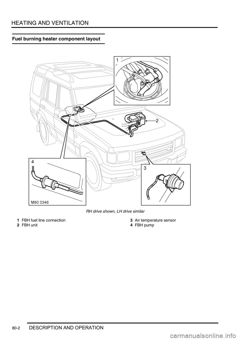
Fuel burning heater component layout
RH drive shown, LH drive similar
1FBH fuel line connection
2FBH unit3Air temperature sensor
4FBH pump
Page 1165 of 1529

HEATING AND VENTILATION
80-8DESCRIPTION AND OPERATION
Control panel
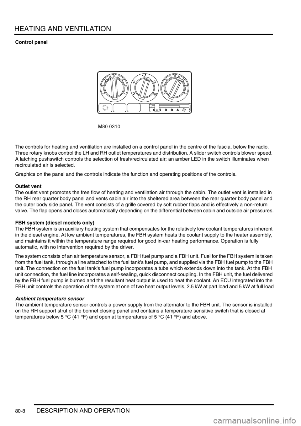
The controls for heating and ventilation are installed on a control panel in the centre of the fascia, below the radio.
Three rotary knobs control the LH and RH outlet temperatures and distribution. A slider switch controls blower speed.
A latching pushswitch controls the selection of fresh/recirculated air; an amber LED in the switch illuminates when
recirculated air is selected.
Graphics on the panel and the controls indicate the function and operating positions of the controls.
Outlet vent
The outlet vent promotes the free flow of heating and ventilation air through the cabin. The outlet vent is installed in
the RH rear quarter body panel and vents cabin air into the sheltered area between the rear quarter body panel and
the outer body side panel. The vent consists of a grille covered by soft rubber flaps and is effectively a non-return
valve. The flap opens and closes automatically depending on the differential between cabin and outside air pressures.
FBH system (diesel models only)
The FBH system is an auxiliary heating system that compensates for the relatively low coolant temperatures inherent
in the diesel engine. At low ambient temperatures, the FBH system heats the coolant supply to the heater assembly,
and maintains it within the temperature range required for good in-car heating performance. Operation is fully
automatic, with no intervention required by the driver.
The system consists of an air temperature sensor, a FBH fuel pump and a FBH unit. Fuel for the FBH system is taken
from the fuel tank, through a line attached to the fuel tank's fuel pump, and supplied via the FBH fuel pump to the FBH
unit. The connection on the fuel tank's fuel pump incorporates a tube which extends down into the tank. At the FBH
unit connection, the fuel line incorporates a self-sealing, quick disconnect coupling. In the FBH unit, the fuel delivered
by the FBH fuel pump is burned and the resultant heat output is used to heat the coolant. An ECU integrated into the
FBH unit controls the operation of the system at one of two heat output levels, 2.5 kW at part load and 5 kW at full load
Ambient temperature sensor
The ambient temperature sensor controls a power supply from the alternator to the FBH unit. The sensor is installed
on the RH support strut of the bonnet closing panel and contains a temperature sensitive switch that is closed at
temperatures below 5 °C (41 °F) and open at temperatures of 5 °C (41 °F) and above.
Page 1166 of 1529

HEATING AND VENTILATION
DESCRIPTION AND OPERATION 80-9
FBH fuel pump
The FBH fuel pump regulates the fuel supply to the FBH unit. The FBH fuel pump is installed in a rubber mounting on
the chassis crossmember immediately in front of the fuel tank. The pump is a self priming, solenoid operated plunger
pump, with a fixed displacement of 0.063 ml/Hz. The ECU in the FBH unit outputs a pulse width modulated signal to
control the operation of the pump. When the pump is de-energised, it provides a positive shut-off of the fuel supply to
the FBH unit.
FBH fuel pump nominal operating speeds/outputs
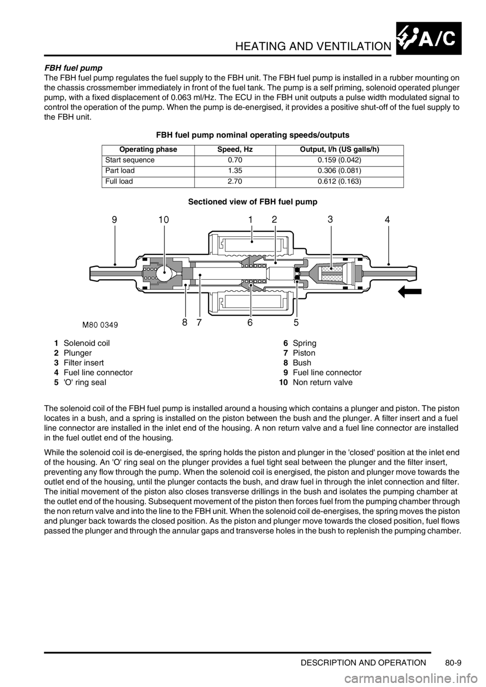
Sectioned view of FBH fuel pump
1Solenoid coil
2Plunger
3Filter insert
4Fuel line connector
5'O' ring seal6Spring
7Piston
8Bush
9Fuel line connector
10Non return valve
The solenoid coil of the FBH fuel pump is installed around a housing which contains a plunger and piston. The piston
locates in a bush, and a spring is installed on the piston between the bush and the plunger. A filter insert and a fuel
line connector are installed in the inlet end of the housing. A non return valve and a fuel line connector are installed
in the fuel outlet end of the housing.
While the solenoid coil is de-energised, the spring holds the piston and plunger in the 'closed' position at the inlet end
of the housing. An 'O' ring seal on the plunger provides a fuel tight seal between the plunger and the filter insert,
preventing any flow through the pump. When the solenoid coil is energised, the piston and plunger move towards the
outlet end of the housing, until the plunger contacts the bush, and draw fuel in through the inlet connection and filter.
The initial movement of the piston also closes transverse drillings in the bush and isolates the pumping chamber at
the outlet end of the housing. Subsequent movement of the piston then forces fuel from the pumping chamber through
the non return valve and into the line to the FBH unit. When the solenoid coil de-energises, the spring moves the piston
and plunger back towards the closed position. As the piston and plunger move towards the closed position, fuel flows
passed the plunger and through the annular gaps and transverse holes in the bush to replenish the pumping chamber.
Operating phase Speed, Hz Output, l/h (US galls/h)
Start sequence 0.70 0.159 (0.042)
Part load 1.35 0.306 (0.081)
Full load 2.70 0.612 (0.163)
Page 1167 of 1529

HEATING AND VENTILATION
80-10DESCRIPTION AND OPERATION
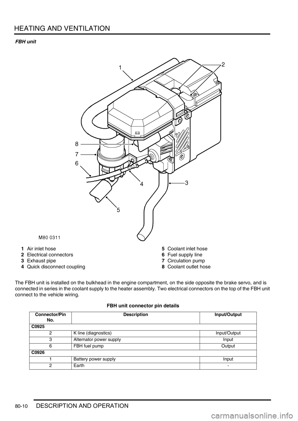
FBH unit
1Air inlet hose
2Electrical connectors
3Exhaust pipe
4Quick disconnect coupling5Coolant inlet hose
6Fuel supply line
7Circulation pump
8Coolant outlet hose
The FBH unit is installed on the bulkhead in the engine compartment, on the side opposite the brake servo, and is
connected in series in the coolant supply to the heater assembly. Two electrical connectors on the top of the FBH unit
connect to the vehicle wiring.
FBH unit connector pin details
Connector/Pin
No.Description Input/Output
C0925
2 K line (diagnostics) Input/Output
3 Alternator power supply Input
6 FBH fuel pump Output
C0926
1 Battery power supply Input
2Earth -