1999 LAND ROVER DISCOVERY engine
[x] Cancel search: enginePage 1140 of 1529
CORROSION PREVENTION AND SEALING
CORROSION PREVENTION 77-4-7
The checks described above are intended to be visual only. It is not intended that the operator should remove trim
panels, finishers, rubbing strips or sound-deadening materials when checking the vehicle for corrosion and paint
damage.
With the vehicle on a lift, and using an inspection or spot lamp, visually check for the following:
lCorrosion damage and damaged paintwork, condition of underbody sealer on front and rear lower panels, sills
and wheel arches;
lDamage to underbody sealer. Corrosion in areas adjacent to suspension mountings and fuel tank fixings.
NOTE: The presence of small blisters in the underbody sealer is acceptable, providing they do not expose bare metal.
Pay special attention to signs of damage caused to panels or corrosion protection material by incorrect jack
positioning.
WARNING: It is essential to follow the correct jacking and lifting procedures.
With the vehicle lowered, visually check for evidence of damage and corrosion on all visible painted areas, in
particular the following:
lFront edge of bonnet;
lVisible flanges in engine compartment;
lLower body and door panels.
Rectify any bodywork damage or evidence of corrosion found during inspection as soon as is practicable, both to
minimise the extent of the damage and to ensure the long term effectiveness of the factory-applied corrosion
prevention treatment. Where the cost of rectification work is the owner's responsibility, the Dealer must advise the
owner and endorse the relevant documentation accordingly.
Where corrosion has become evident and is emanating from beneath a removable component (e.g. trim panel,
window glass, seat etc.), remove the component as required to permit effective rectification.
Underbody protection repairs
Whenever body repairs are carried out, ensure that full sealing and corrosion protection treatments are reinstated.
This applies both to the damaged areas and also to areas where protection has been indirectly impaired, as a result
either of accident damage or repair operations.
Remove corrosion protection from the damaged area before straightening or panel beating. This applies in particular
to panels coated with wax, PVC underbody sealer, sound deadening pads etc.
WARNING: DO NOT use oxy-acetylene gas equipment to remove corrosion prevention materials. Large
volumes of fumes and gases are liberated by these materials when they burn.
NOTE: Equipment for the removal of tough anti-corrosion sealers offers varying degrees of speed and effectiveness.
The compressed air-operated scraper (NOT an air chisel) offers a relatively quiet mechanical method using an
extremely rapid reciprocating action. Move the operating end of the tool along the work surface to remove the material.
The most common method of removal is by means of a hot air blower with integral scraper.
Another tool, and one of the most efficient methods, is the rapid-cutting 'hot knife'. This tool uses a wide blade and is
quick and versatile, able to be used easily in profiled sections where access is otherwise difficult.
Use the following procedure when repairing underbody coatings:
1Remove existing underbody coatings
2After panel repair, clean the affected area with a solvent wipe, and treat bare metal with an etch phosphate
material
3Re-prime the affected area
CAUTION: DO NOT, under any circumstances, apply underbody sealer directly to bare metal surfaces.
4Replace all heat-fusible plugs which have been disturbed. Where such plugs are not available use rubber
grommets of equivalent size, ensuring that they are embedded in sealer
5Mask off all mounting faces from which mechanical components, hoses and pipe clips, have been removed.
Underbody sealer must be applied before such components are refitted
6Brush sealer into all exposed seams
7Spray the affected area with an approved service underbody sealer
8Remove masking from component mounting faces, and touch-in where necessary. Allow adequate drying time
before applying underbody wax
Page 1141 of 1529

CORROSION PREVENTION AND SEALING
77-4-8 CORROSION PREVENTION
After refitting mechanical components, including hoses and pipes and other fixtures, mask off the brake discs and
apply a coat of approved underbody wax.
NOTE: Where repairs include the application of finish paint coats in the areas requiring underbody wax, carry out paint
operations before applying wax.
Cavity wax injection
Areas treated with cavity wax are shown in the previous figures. After repairs, always re-treat these areas with an
approved cavity wax. In addition, treat all interior surfaces which have been disturbed during repairs whether they
have been treated in production or not. This includes all box members, cavities and door interiors. It is permissible to
drill extra holes for access where necessary, provided these are not positioned in load-bearing members. Ensure that
such holes are treated with a suitable zinc rich primer, brushed with wax and then sealed with a rubber grommet.
Before wax injection, ensure that the cavity to be treated is free from any contamination or foreign matter. Where
necessary, clear out any debris using compressed air.
Ensure that cavity wax is applied AFTER the final paint process and BEFORE refitting any trim components.
During application, ensure that the wax covers all flange and seam areas and that it is adequately applied to all
repaired areas of both new and existing panels.
It should be noted that new panel assemblies and complete body shells are supplied without wax injection treatment.
Ensure that such treatment is carried out after repairs.
Effective cavity wax protection is vital. Always observe the following points:
lComplete all paint refinish operations before wax application;
lClean body panel areas and blow-clean cavities if necessary, before treatment;
lMaintain a temperature of 18° C (64° F) during application and drying;
lCheck the spray pattern of injection equipment;
lMask off all areas not to be wax coated and which could be contaminated by wax overspray;
lRemove body fixings, such as seat belt retractors, if contamination is at all likely;
lMove door glasses to fully closed position before treating door interiors;
lTreat body areas normally covered by trim before refitting items;
lCheck that body and door drain holes are clear after the protective wax has dried;
lKeep all equipment clean, especially wax injection nozzles.
Underbody wax
The underbody wax must be reinstated following all repairs affecting floor panels. The wax is applied over paints and
underbody sealers.
Remove old underbody wax completely from a zone extending at least 200 mm (7.874 in) beyond the area where new
underbody sealer is to be applied.
Engine bay wax
Reinstate all protective engine bay wax disturbed during repairs using an approved material.
Where repairs have involved replacement of engine bay panels, treat the entire engine compartment including all
components, clips and other fixtures with an approved underbonnet lacquer or wax.
+ BODY SEALING MATERIALS, MATERIALS AND APPLICATIONS, Approved materials.
Page 1160 of 1529

HEATING AND VENTILATION
DESCRIPTION AND OPERATION 80-3
Description
General
The heating and ventilation system controls the temperature and distribution of air supplied to the vehicle interior. The
system consists of an air inlet duct, heater assembly, distribution ducts and a control panel. An outlet vent is
incorporated at the rear of the cabin. Some diesel models also incorporate a fuel burning heater (FBH) system in the
engine coolant supply to the heater assembly.
Fresh or recirculated air flows into the heater assembly from the inlet duct. An electrical variable speed blower in the
inlet duct, and/or ram effect, forces the air through the system. Depending on the settings on the control panel, the air
is then heated and supplied through the distribution ducts to fascia and floor level outlets.
Page 1162 of 1529
HEATING AND VENTILATION
DESCRIPTION AND OPERATION 80-5
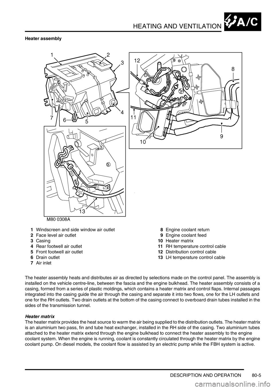
Heater assembly
1Windscreen and side window air outlet
2Face level air outlet
3Casing
4Rear footwell air outlet
5Front footwell air outlet
6Drain outlet
7Air inlet8Engine coolant return
9Engine coolant feed
10Heater matrix
11RH temperature control cable
12Distribution control cable
13LH temperature control cable
The heater assembly heats and distributes air as directed by selections made on the control panel. The assembly is
installed on the vehicle centre-line, between the fascia and the engine bulkhead. The heater assembly consists of a
casing, formed from a series of plastic moldings, which contains a heater matrix and control flaps. Internal passages
integrated into the casing guide the air through the casing and separate it into two flows, one for the LH outlets and
one for the RH outlets. Two drain outlets at the bottom of the casing connect to overboard drain tubes installed in the
sides of the transmission tunnel.
Heater matrix
The heater matrix provides the heat source to warm the air being supplied to the distribution outlets. The heater matrix
is an aluminium two pass, fin and tube heat exchanger, installed in the RH side of the casing. Two aluminium tubes
attached to the heater matrix extend through the engine bulkhead to connect the heater assembly to the engine
coolant system. When the engine is running, coolant is constantly circulated through the heater matrix by the engine
coolant pump. On diesel models, the coolant flow is assisted by an electric pump while the FBH system is active.
Page 1165 of 1529
HEATING AND VENTILATION
80-8DESCRIPTION AND OPERATION
Control panel
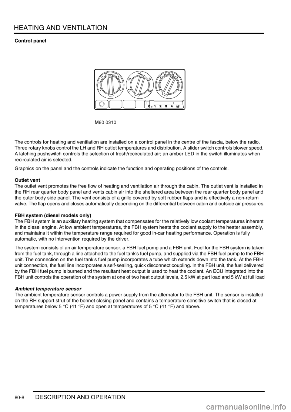
The controls for heating and ventilation are installed on a control panel in the centre of the fascia, below the radio.
Three rotary knobs control the LH and RH outlet temperatures and distribution. A slider switch controls blower speed.
A latching pushswitch controls the selection of fresh/recirculated air; an amber LED in the switch illuminates when
recirculated air is selected.
Graphics on the panel and the controls indicate the function and operating positions of the controls.
Outlet vent
The outlet vent promotes the free flow of heating and ventilation air through the cabin. The outlet vent is installed in
the RH rear quarter body panel and vents cabin air into the sheltered area between the rear quarter body panel and
the outer body side panel. The vent consists of a grille covered by soft rubber flaps and is effectively a non-return
valve. The flap opens and closes automatically depending on the differential between cabin and outside air pressures.
FBH system (diesel models only)
The FBH system is an auxiliary heating system that compensates for the relatively low coolant temperatures inherent
in the diesel engine. At low ambient temperatures, the FBH system heats the coolant supply to the heater assembly,
and maintains it within the temperature range required for good in-car heating performance. Operation is fully
automatic, with no intervention required by the driver.
The system consists of an air temperature sensor, a FBH fuel pump and a FBH unit. Fuel for the FBH system is taken
from the fuel tank, through a line attached to the fuel tank's fuel pump, and supplied via the FBH fuel pump to the FBH
unit. The connection on the fuel tank's fuel pump incorporates a tube which extends down into the tank. At the FBH
unit connection, the fuel line incorporates a self-sealing, quick disconnect coupling. In the FBH unit, the fuel delivered
by the FBH fuel pump is burned and the resultant heat output is used to heat the coolant. An ECU integrated into the
FBH unit controls the operation of the system at one of two heat output levels, 2.5 kW at part load and 5 kW at full load
Ambient temperature sensor
The ambient temperature sensor controls a power supply from the alternator to the FBH unit. The sensor is installed
on the RH support strut of the bonnet closing panel and contains a temperature sensitive switch that is closed at
temperatures below 5 °C (41 °F) and open at temperatures of 5 °C (41 °F) and above.
Page 1167 of 1529
HEATING AND VENTILATION
80-10DESCRIPTION AND OPERATION
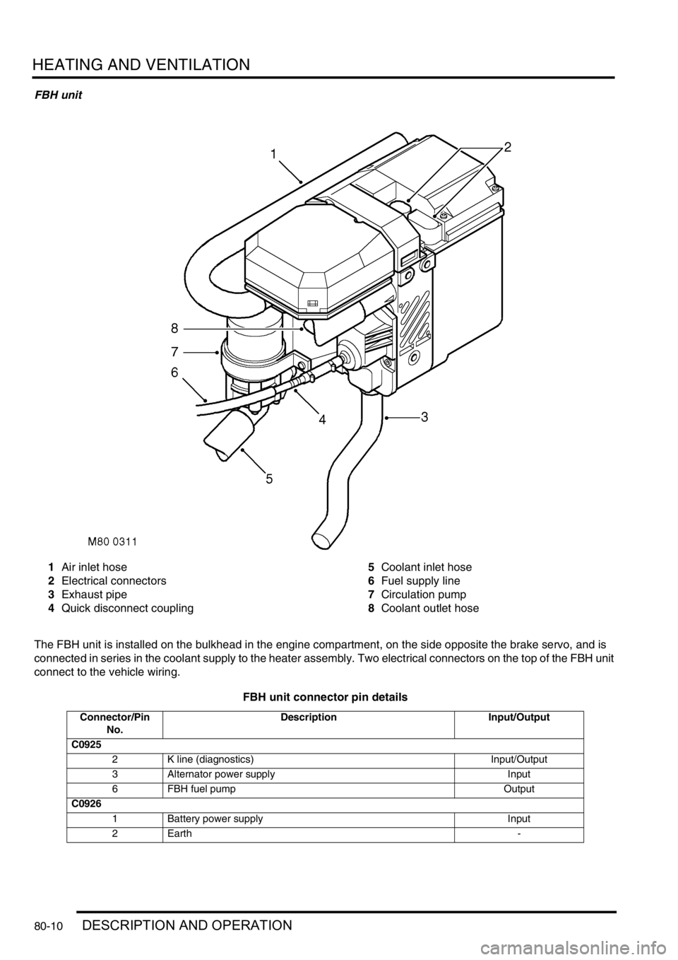
FBH unit
1Air inlet hose
2Electrical connectors
3Exhaust pipe
4Quick disconnect coupling5Coolant inlet hose
6Fuel supply line
7Circulation pump
8Coolant outlet hose
The FBH unit is installed on the bulkhead in the engine compartment, on the side opposite the brake servo, and is
connected in series in the coolant supply to the heater assembly. Two electrical connectors on the top of the FBH unit
connect to the vehicle wiring.
FBH unit connector pin details
Connector/Pin
No.Description Input/Output
C0925
2 K line (diagnostics) Input/Output
3 Alternator power supply Input
6 FBH fuel pump Output
C0926
1 Battery power supply Input
2Earth -
Page 1168 of 1529
HEATING AND VENTILATION
DESCRIPTION AND OPERATION 80-11
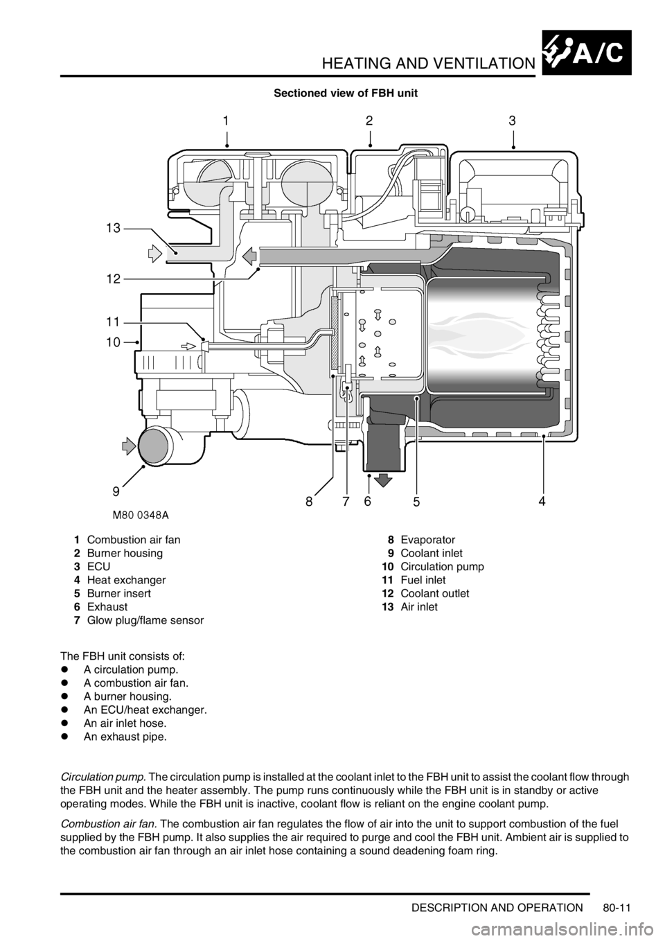
Sectioned view of FBH unit
1Combustion air fan
2Burner housing
3ECU
4Heat exchanger
5Burner insert
6Exhaust
7Glow plug/flame sensor8Evaporator
9Coolant inlet
10Circulation pump
11Fuel inlet
12Coolant outlet
13Air inlet
The FBH unit consists of:
lA circulation pump.
lA combustion air fan.
lA burner housing.
lAn ECU/heat exchanger.
lAn air inlet hose.
lAn exhaust pipe.
Circulation pump. The circulation pump is installed at the coolant inlet to the FBH unit to assist the coolant flow through
the FBH unit and the heater assembly. The pump runs continuously while the FBH unit is in standby or active
operating modes. While the FBH unit is inactive, coolant flow is reliant on the engine coolant pump.
Combustion air fan. The combustion air fan regulates the flow of air into the unit to support combustion of the fuel
supplied by the FBH pump. It also supplies the air required to purge and cool the FBH unit. Ambient air is supplied to
the combustion air fan through an air inlet hose containing a sound deadening foam ring.
Page 1169 of 1529

HEATING AND VENTILATION
80-12DESCRIPTION AND OPERATION
Burner housing. The burner housing contains the burner insert and also incorporates connections for the exhaust
pipe, the coolant inlet from the circulation pump and the coolant outlet to the heater assembly. The exhaust pipe
directs exhaust combustion gases to atmosphere at the bottom of the engine compartment.
The burner insert incorporates the fuel combustion chamber, an evaporator and a glow plug/flame sensor. Fuel from
the FBH fuel pump is supplied to the evaporator, where it evaporates and enters the combustion chamber to mix with
air from the combustion air fan. The glow plug/flame sensor provides the ignition source of the fuel:air mixture and,
once combustion is established, monitors the flame.
ECU/heat exchanger. The ECU controls and monitors operation of the FBH system. Ventilation of the ECU is
provided by an internal flow of air from the combustion air fan. The heat exchanger transfers heat generated by
combustion to the coolant. A sensor in the heat exchanger provides the ECU with an input of heat exchanger casing
temperature, which the ECU relates to coolant temperature and uses to control system operation. The temperature
settings in the ECU are calibrated to compensate for the difference between coolant temperature and the heat
exchanger casing temperature detected by the sensor. Typically: as the coolant temperature increases, the coolant
will be approximately 7 °C (12.6 °F) hotter than the temperature detected by the sensor; as the coolant temperature
decreases, the coolant will be approximately 2 °C (3.6 °F) cooler than the temperature detected by the sensor.