Page 828 of 1529

REAR SUSPENSION
DESCRIPTION AND OPERATION 64-19
Failure modes
Failures are indicated by the SLS warning lamp in the bottom left corner of the instrument pack illuminating
continuously in an amber colour. The following tables show the type of system failures and their effects on the system
operation.
Height sensors
Door Switch Inputs
Connector/Pin
No.Description Input/Output
C0504
1 Battery supply Input
2 Ignition supply Input
5 K line (diagnostics) Input/Output
12 Earth Input
C0654
1 Left height sensor supply Output
2 Left height sensor earth Input
3 Left height sensor signal Input
4 Right height sensor supply Output
5 Right height sensor earth Input
6 Right height sensor signal Input
C0655
1 Driver's door switch Input
2 Passenger and tail door switches Input
3 Left air valve Output
4 Right air valve Output
5 Exhaust valve Output
6 Air compressor (SLS relay) Output
7 Audible warning Output
8 SLS warning lamp Output
11 ORM switch/ORM warning lamp Input/Output
12 Remote handset raise/lower signal Input
Connectors and pins not listed are either not used or used by the brakes system.
+ BRAKES, DESCRIPTION AND OPERATION, Description.
Failure Effect
Sensor output stuck at 5 V Vehicle will not level
Sensor output stuck at 0 V Vehicle will not level
Mechanical link between radius arm and sensor
brokenVehicle will not level
Failure Effect
Harness leads for open doors are are broken or
shorted to V Batt.Air suspension levels when one or more doors
are open
Harness leads to door(s) shorted to earth Air suspension will not level
Page 836 of 1529
REAR SUSPENSION
REPAIRS 64-27
REPAIRS
Wheel hub
$% 64.15.01
Models with SLS:
WARNING: Ensure the air suspension system is
made safe before commencing work. Otherwise
the chassis may lower onto the bump stops
during repair.
Remove
1.Raise rear of vehicle.
WARNING: Do not work on or under a
vehicle supported only by a jack. Always
support the vehicle on safety stands.
2.Remove road wheel.
3.Release stake in drive shaft nut.
4.With an assistant depressing the brake pedal,
remove and discard drive shaft nut.
5.Remove rear brake disc.
+ BRAKES, REPAIRS, Brake disc -
rear.6.Disconnect ABS sensor multiplug.
7.Release harness from brake hose and hose
bracket.
8.Remove 4 bolts securing wheel hub to axle.
9.Release and remove wheel hub and drive shaft
assembly from axle. Remove and discard 'O'
ring from wheel hub.
Page 837 of 1529

REAR SUSPENSION
64-28 REPAIRS
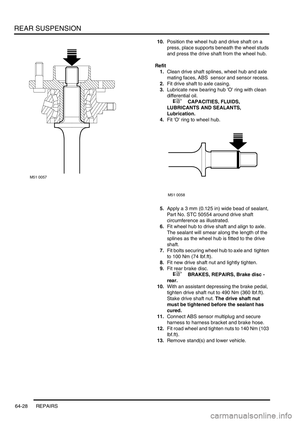
10.Position the wheel hub and drive shaft on a
press, place supports beneath the wheel studs
and press the drive shaft from the wheel hub.
Refit
1.Clean drive shaft splines, wheel hub and axle
mating faces, ABS sensor and sensor recess.
2.Fit drive shaft to axle casing.
3.Lubricate new bearing hub 'O' ring with clean
differential oil.
+ CAPACITIES, FLUIDS,
LUBRICANTS AND SEALANTS,
Lubrication.
4.Fit 'O' ring to wheel hub.
5.Apply a 3 mm (0.125 in) wide bead of sealant,
Part No. STC 50554 around drive shaft
circumference as illustrated.
6.Fit wheel hub to drive shaft and align to axle.
The sealant will smear along the length of the
splines as the wheel hub is fitted to the drive
shaft.
7.Fit bolts securing wheel hub to axle and tighten
to 100 Nm (74 lbf.ft).
8.Fit new drive shaft nut and lightly tighten.
9.Fit rear brake disc.
+ BRAKES, REPAIRS, Brake disc -
rear.
10.With an assistant depressing the brake pedal,
tighten drive shaft nut to 490 Nm (360 lbf.ft).
Stake drive shaft nut. The drive shaft nut
must be tightened before the sealant has
cured.
11.Connect ABS sensor multiplug and secure
harness to harness bracket and brake hose.
12.Fit road wheel and tighten nuts to 140 Nm (103
lbf.ft).
13.Remove stand(s) and lower vehicle.
M51 0057
M51 0058
Page 838 of 1529

REAR SUSPENSION
REPAIRS 64-29
Road spring - rear
$% 64.20.01
Remove
1.Raise rear of vehicle.
WARNING: Do not work on or under a
vehicle supported only by a jack. Always
support the vehicle on safety stands.
2.Support vehicle under chassis.
3.Remove road wheel.
4.Support weight of axle on a jack.
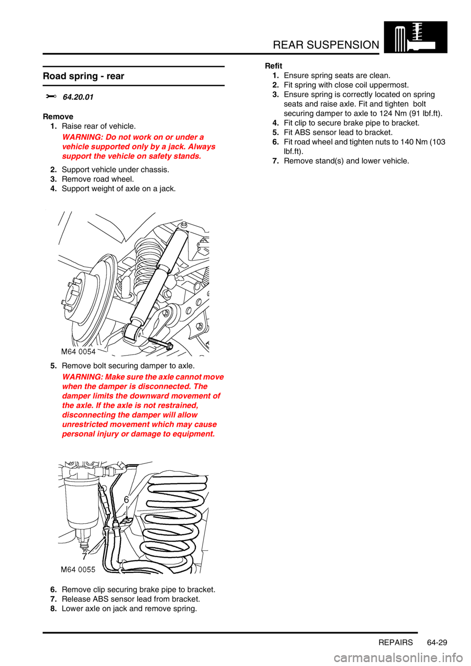
5.Remove bolt securing damper to axle.
WARNING: Make sure the axle cannot move
when the damper is disconnected. The
damper limits the downward movement of
the axle. If the axle is not restrained,
disconnecting the damper will allow
unrestricted movement which may cause
personal injury or damage to equipment.
6.Remove clip securing brake pipe to bracket.
7.Release ABS sensor lead from bracket.
8.Lower axle on jack and remove spring.Refit
1.Ensure spring seats are clean.
2.Fit spring with close coil uppermost.
3.Ensure spring is correctly located on spring
seats and raise axle. Fit and tighten bolt
securing damper to axle to 124 Nm (91 lbf.ft).
4.Fit clip to secure brake pipe to bracket.
5.Fit ABS sensor lead to bracket.
6.Fit road wheel and tighten nuts to 140 Nm (103
lbf.ft).
7.Remove stand(s) and lower vehicle.
Page 854 of 1529
BRAKES
DESCRIPTION AND OPERATION 70-1
BRAKES DESCRIPTION AND OPERAT ION
Brake system control component layout
RH drive shown, LH drive similar
1Hill descent switch
2ABS sensor3SLABS ECU
Page 856 of 1529
BRAKES
DESCRIPTION AND OPERATION 70-3
1ABS sensor
2ABS modulator
3Return pump relay
4SLABS ECU
5Brake lamp relay
6Centre high mounted stop lamp
7LH brake lamp
8RH brake lamp
9Instrument pack10Body control unit
11Reverse lamp switch (manual gearbox)
12Diagnostic socket
13HDC switch
14Transmission high/low switch
15Centre differential lock switch
16Engine control module
17Battery power supply
18Ignition power supply
Page 871 of 1529

BRAKES
70-18 DESCRIPTION AND OPERATION
The SLABS ECU continually calculates vehicle speed using the wheel speed inputs from all four ABS sensors. The
calculated vehicle speed is then used as a reference against which individual wheel speeds are monitored for
unacceptable acceleration or deceleration. The ABS sensor inputs are also used by the SLABS ECU to detect vehicle
deceleration rate, vehicle cornering rate and rough terrain.
The engaged forward gear and (on manual gearbox models) the clutch status are computed from the engine data
input, the engine speed input and vehicle speed. Reverse gear status is provided by an input from the reverse lamp
switch (manual gearbox models) or the BCU (automatic gearbox models). On automatic models, the BCU also
provides the neutral selected input.
In addition to controlling the brake related functions, the SLABS ECU:
lControls the operation of the self levelling suspension (SLS) system (where fitted).
+ REAR SUSPENSION, DESCRIPTION AND OPERATION, Description.
lOn V8 models, outputs a rough road signal to the ECM when traversing rough terrain.
lOutputs a vehicle speed signal.
The vehicle speed signal is output to the following systems (where fitted):
lActive Cornering Enhancement.
+ FRONT SUSPENSION, DESCRIPTION AND OPERATION, Description - ACE.
lAir conditioning.
+ AIR CONDITIONING, DESCRIPTION AND OPERATION, Description.
lCruise control.
+ ENGINE MANAGEMENT SYSTEM - Td5, DESCRIPTION AND OPERATION, Description.
+ ENGINE MANAGEMENT SYSTEM - V8, DESCRIPTION AND OPERATION, Description - engine
management.
lEngine management.
+ ENGINE MANAGEMENT SYSTEM - Td5, DESCRIPTION AND OPERATION, Description.
+ ENGINE MANAGEMENT SYSTEM - V8, DESCRIPTION AND OPERATION, Description - engine
management.
lIn-car entertainment.
+ IN CAR ENTERTAINMENT, DESCRIPTION AND OPERATION, Description.
lInstrument pack.
+ INSTRUMENTS, DESCRIPTION AND OPERATION, Description.
5 Front right inlet solenoid valve Output
6 Shuttle valve switches Input
7 Rear left outlet solenoid valve Output
8 Rear left inlet solenoid valve Output
9 Centre differential lock switch Input
10 Rear right outlet solenoid valve Output
11 Rear right inlet solenoid valve Output
12 Brake lamp relay Output
15 Return pump relay Output
C0655
7 Audible warning Output
10 Engine speed Input
Connector and pins not listed are either not used or used by the self levelling suspension system.
+ REAR SUSPENSION, DESCRIPTION AND OPERATION, Description.
Connector/Pin
No.Description Input/Output
Page 872 of 1529

BRAKES
DESCRIPTION AND OPERATION 70-19
ABS sensors
The ABS sensors supply the SLABS ECU with a sinusoidal speed signal from each wheel. An inductive sensor,
installed in the hub bearing of each wheel, senses off a 60 tooth exciter ring integrated into the inner race of the hub
bearing. Each ABS sensor has a fly-lead connecting it to the vehicle wiring.
HDC switch
The HDC switch is a latching push switch installed on the fascia, in the switchpack inboard of the steering wheel.
When pushed in, the switch connects an ignition supply to the SLABS ECU to initiate HDC.
Warning indications
The SLABS ECU operates audible and visual warnings to convey brake system status.
Audible warning
A repetitive chime, at a frequency of 2 Hz, draws attention to warning lamp indications. The chime is produced on the
speaker in the instrument pack.
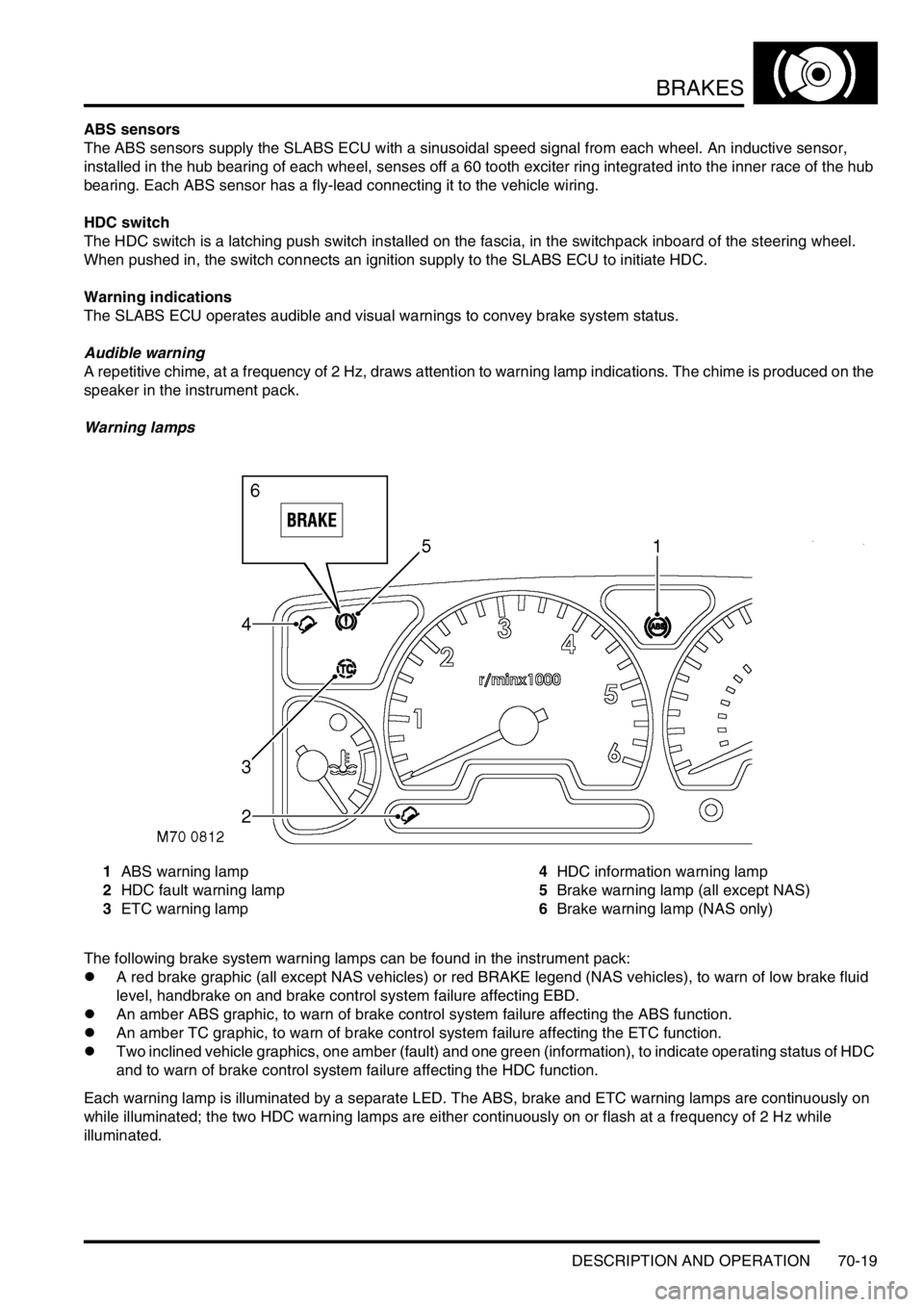
Warning lamps
1ABS warning lamp
2HDC fault warning lamp
3ETC warning lamp4HDC information warning lamp
5Brake warning lamp (all except NAS)
6Brake warning lamp (NAS only)
The following brake system warning lamps can be found in the instrument pack:
lA red brake graphic (all except NAS vehicles) or red BRAKE legend (NAS vehicles), to warn of low brake fluid
level, handbrake on and brake control system failure affecting EBD.
lAn amber ABS graphic, to warn of brake control system failure affecting the ABS function.
lAn amber TC graphic, to warn of brake control system failure affecting the ETC function.
lTwo inclined vehicle graphics, one amber (fault) and one green (information), to indicate operating status of HDC
and to warn of brake control system failure affecting the HDC function.
Each warning lamp is illuminated by a separate LED. The ABS, brake and ETC warning lamps are continuously on
while illuminated; the two HDC warning lamps are either continuously on or flash at a frequency of 2 Hz while
illuminated.