Page 863 of 1529
BRAKES
70-10 DESCRIPTION AND OPERATION
Vacuum pump (diesel models only)
1Alternator
2Vacuum pump
3Brake servo assembly vacuum connection4Oil feed pipe
5Oil drain pipe
As the diesel engine air inlet system does not produce sufficient depression to operate the brake servo assembly, an
engine driven vacuum pump is installed.
The vacuum pump is integrated with the engine alternator and driven by the auxiliary drive belt. The pump is a rotary
vane type, lubricated and cooled by engine oil supplied through a pipe connected to the engine block and returned
through a pipe connected to the engine oil sump. Air extracted from the brake servo assembly is vented into the oil
sump with returning lubricating oil.
Page 1216 of 1529

AIR CONDITIONING
REFRIGERANT RECOVERY, RECYCLING AND RECHARGING 82-27
REFRIGERANT RECOVERY, RECYCLING AND RECHARGING
Refrigerant recovery, recycling and
recharging
$% 82.30.02
Recovery
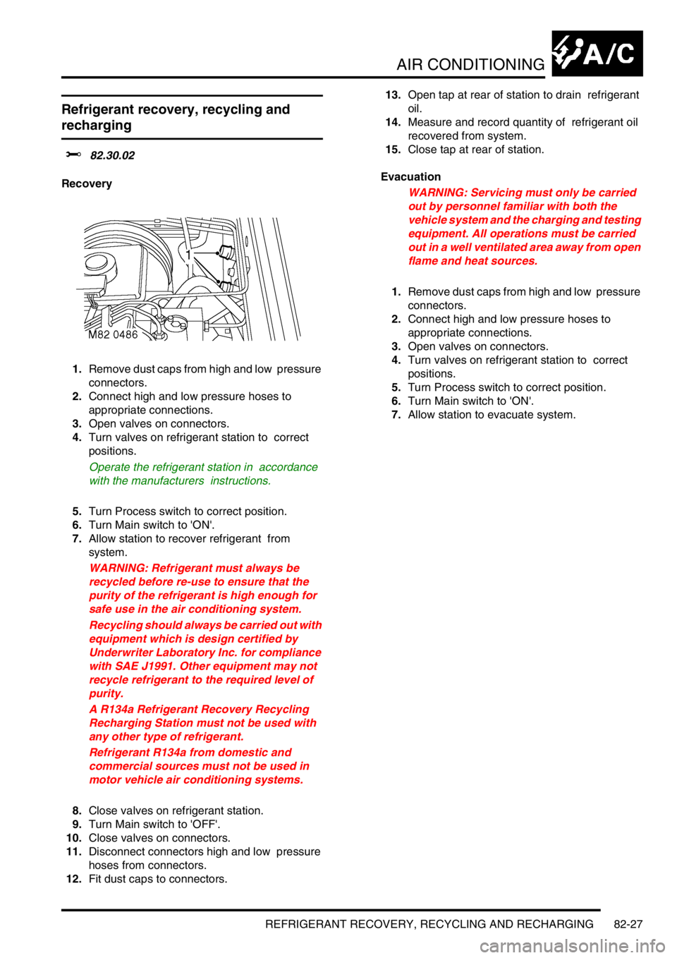
1.Remove dust caps from high and low pressure
connectors.
2.Connect high and low pressure hoses to
appropriate connections.
3.Open valves on connectors.
4.Turn valves on refrigerant station to correct
positions.
Operate the refrigerant station in accordance
with the manufacturers instructions.
5.Turn Process switch to correct position.
6.Turn Main switch to 'ON'.
7.Allow station to recover refrigerant from
system.
WARNING: Refrigerant must always be
recycled before re-use to ensure that the
purity of the refrigerant is high enough for
safe use in the air conditioning system.
Recycling should always be carried out with
equipment which is design certified by
Underwriter Laboratory Inc. for compliance
with SAE J1991. Other equipment may not
recycle refrigerant to the required level of
purity.
A R134a Refrigerant Recovery Recycling
Recharging Station must not be used with
any other type of refrigerant.
Refrigerant R134a from domestic and
commercial sources must not be used in
motor vehicle air conditioning systems.
8.Close valves on refrigerant station.
9.Turn Main switch to 'OFF'.
10.Close valves on connectors.
11.Disconnect connectors high and low pressure
hoses from connectors.
12.Fit dust caps to connectors. 13.Open tap at rear of station to drain refrigerant
oil.
14.Measure and record quantity of refrigerant oil
recovered from system.
15.Close tap at rear of station.
Evacuation
WARNING: Servicing must only be carried
out by personnel familiar with both the
vehicle system and the charging and testing
equipment. All operations must be carried
out in a well ventilated area away from open
flame and heat sources.
1.Remove dust caps from high and low pressure
connectors.
2.Connect high and low pressure hoses to
appropriate connections.
3.Open valves on connectors.
4.Turn valves on refrigerant station to correct
positions.
5.Turn Process switch to correct position.
6.Turn Main switch to 'ON'.
7.Allow station to evacuate system.
Page 1516 of 1529

INSTRUMENTS
DESCRIPTION AND OPERATION 88-33
Engine oil pressure warning lamp
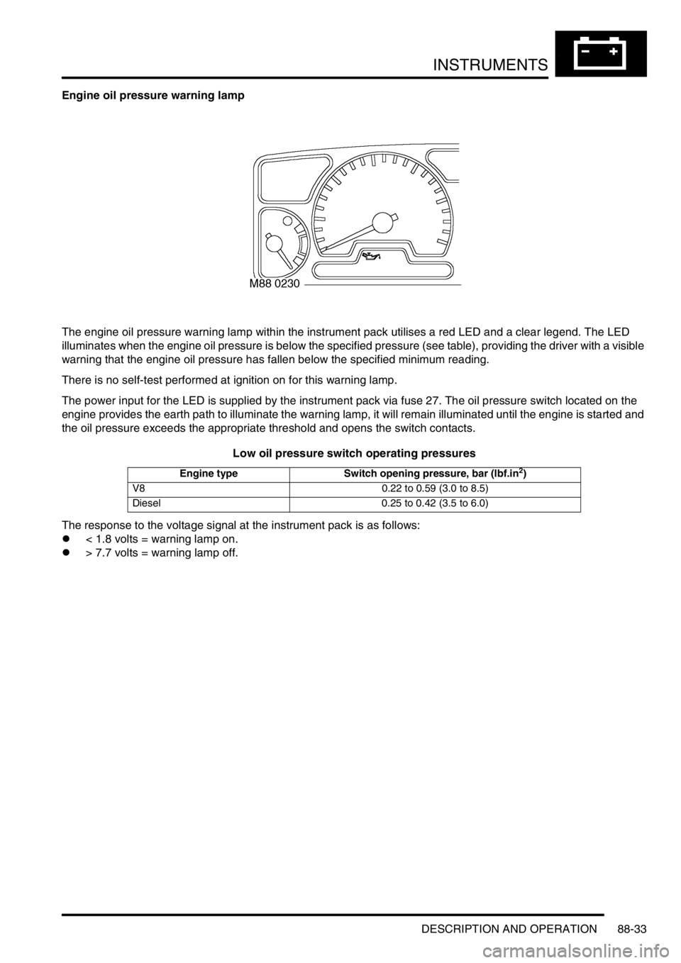
The engine oil pressure warning lamp within the instrument pack utilises a red LED and a clear legend. The LED
illuminates when the engine oil pressure is below the specified pressure (see table), providing the driver with a visible
warning that the engine oil pressure has fallen below the specified minimum reading.
There is no self-test performed at ignition on for this warning lamp.
The power input for the LED is supplied by the instrument pack via fuse 27. The oil pressure switch located on the
engine provides the earth path to illuminate the warning lamp, it will remain illuminated until the engine is started and
the oil pressure exceeds the appropriate threshold and opens the switch contacts.
Low oil pressure switch operating pressures
The response to the voltage signal at the instrument pack is as follows:
l< 1.8 volts = warning lamp on.
l> 7.7 volts = warning lamp off.
Engine type Switch opening pressure, bar (lbf.in2)
V8 0.22 to 0.59 (3.0 to 8.5)
Diesel 0.25 to 0.42 (3.5 to 6.0)