Page 1467 of 1529

NAVIGATION SYSTEM
87-14 DESCRIPTION AND OPERATION
Description
General
Where fitted, the CARiN III and Trafficmaster system combines a satellite navigation system (CARiN III) with a real-
time traffic information system (Trafficmaster).
The satellite navigation system provides computer generated audible and visual route guidance information to enable
the driver to reach a desired destination. The system allows the driver to choose between road navigation and off-
road navigation, and to incorporate waypoints. Road navigation also allows the driver to choose between using minor
or major roads and the quickest or shortest route. Directions to hospitals, museums, monuments, hotels etc. are also
available. The computer uses map information stored on a CD-ROM to determine the best route for the journey and
provide the driver with details of directions and approaching junctions. The current position of the vehicle is
determined using a combination of vehicle sensor inputs and the Global Positioning System (GPS).
The Trafficmaster system displays live traffic flow information on the road navigation map screens. Traffic speed is
indicated on the maps by colour coded roads and arrows. The traffic flow information is relayed from a network of
sensors covering motorways and trunk roads. Data from the sensors is updated on a three minute cycle, 24 hours a
day, 365 days a year.
The navigation system consists of the following components:
lNavigation computer
lGPS antenna
lDisplay unit
lSwitch pack
lNavigation speaker
lTrafficmaster monitor ECU
lTrafficmaster antenna
Navigation Computer
The navigation computer is located in a bracket under the RH front seat, immediately behind the CD autochanger.
The navigation computer contains all the hardware and software required for control of the navigation system,
including the GPS receiver and a solid state piezo gyro. Using the gyro, and inputs from the GPS antenna and the
vehicle K bus, the navigation computer determines the vehicle’s current position, direction and speed.
The navigation computer also houses a CD-ROM drive. The drive is used to read map data from country specific CD’s
and also to load software into the computer. A button, adjacent to the CD slot, is provided to eject the CD from the
unit. If the ignition is on, one press of the button will eject the CD. If the ignition is off, two presses are required, one
to wake up the system and the second to eject the CD. Access to the CD-ROM drive is from the rear of the RH front
seat.
Page 1468 of 1529
NAVIGATION SYSTEM
DESCRIPTION AND OPERATION 87-15
Navigation Computer
The Navigation computer is delivered pre-loaded with operating software, 2 languages and the Off Road navigation
software. The 2 pre-loaded languages are:
lUK English (Female)
lGerman (Male)
Software loading can be achieved at any time by inserting a software CD into the CD-ROM drive. The navigation
computer compares the version of software on the CD with that currently loaded. If the software version on the CD is
a later version it automatically loads the new software. The status of software loading is shown on the display unit.
On completion of software loading, the CD is automatically ejected. The user is prompted to remove the CD and
confirm. The computer then resets and restarts with the new software.
M86 6061
ON
CD-IN
Page 1470 of 1529
NAVIGATION SYSTEM
DESCRIPTION AND OPERATION 87-17
GPS Antenna
The GPS antenna is installed on the rear of the roof, on the vehicle centreline. A diplexer unit on the underside of the
GPS antenna amplifies the radio signals received from the GPS satellites and transmits them through a co-axial cable
to the navigation computer for processing.
Display Unit
The display unit is integrated into the front stowage pocket, above the rear view mirror. The display unit is a colour
Liquid Crystal Display (LCD) that shows the programming menus, route guidance and traffic information. The display
illumination level automatically dims for night time viewing when the exterior lights are switched on.
Page 1471 of 1529

NAVIGATION SYSTEM
87-18 DESCRIPTION AND OPERATION
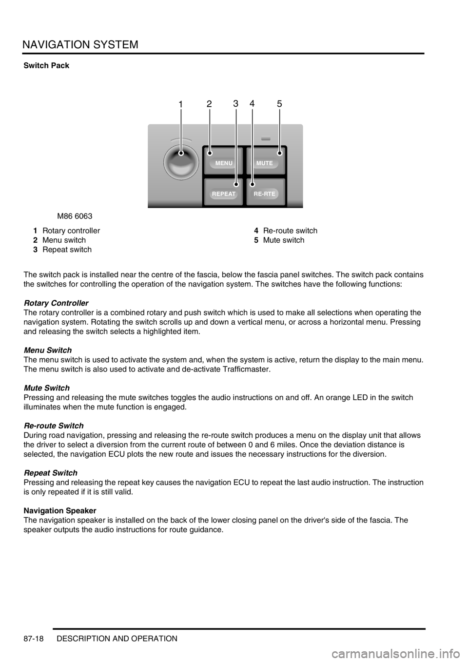
Switch Pack
1Rotary controller
2Menu switch
3Repeat switch4Re-route switch
5Mute switch
The switch pack is installed near the centre of the fascia, below the fascia panel switches. The switch pack contains
the switches for controlling the operation of the navigation system. The switches have the following functions:
Rotary Controller
The rotary controller is a combined rotary and push switch which is used to make all selections when operating the
navigation system. Rotating the switch scrolls up and down a vertical menu, or across a horizontal menu. Pressing
and releasing the switch selects a highlighted item.
Menu Switch
The menu switch is used to activate the system and, when the system is active, return the display to the main menu.
The menu switch is also used to activate and de-activate Trafficmaster.
Mute Switch
Pressing and releasing the mute switches toggles the audio instructions on and off. An orange LED in the switch
illuminates when the mute function is engaged.
Re-route Switch
During road navigation, pressing and releasing the re-route switch produces a menu on the display unit that allows
the driver to select a diversion from the current route of between 0 and 6 miles. Once the deviation distance is
selected, the navigation ECU plots the new route and issues the necessary instructions for the diversion.
Repeat Switch
Pressing and releasing the repeat key causes the navigation ECU to repeat the last audio instruction. The instruction
is only repeated if it is still valid.
Navigation Speaker
The navigation speaker is installed on the back of the lower closing panel on the driver's side of the fascia. The
speaker outputs the audio instructions for route guidance.
M86 6063
1
MUTE
RE-RTE
REPEAT
MENU
2345
Page 1472 of 1529
NAVIGATION SYSTEM
DESCRIPTION AND OPERATION 87-19
Trafficmaster Monitor ECU
The Trafficmaster monitor ECU is installed underneath the CD autochanger, below the RH front seat. The
Trafficmaster monitor ECU processes the traffic flow data from the Trafficmaster antenna and combines it with data
from the navigation computer to display on the display unit.
Trafficmaster Antenna
The Trafficmaster antenna is installed in the fascia, on the rear of the instrument pack. The antenna receives radio
signals containing the data relayed from the traffic flow sensors, and transmits the information on a hardwired
connection to the Trafficmaster monitor ECU.
Page 1473 of 1529

NAVIGATION SYSTEM
87-20 DESCRIPTION AND OPERATION
Operation
General
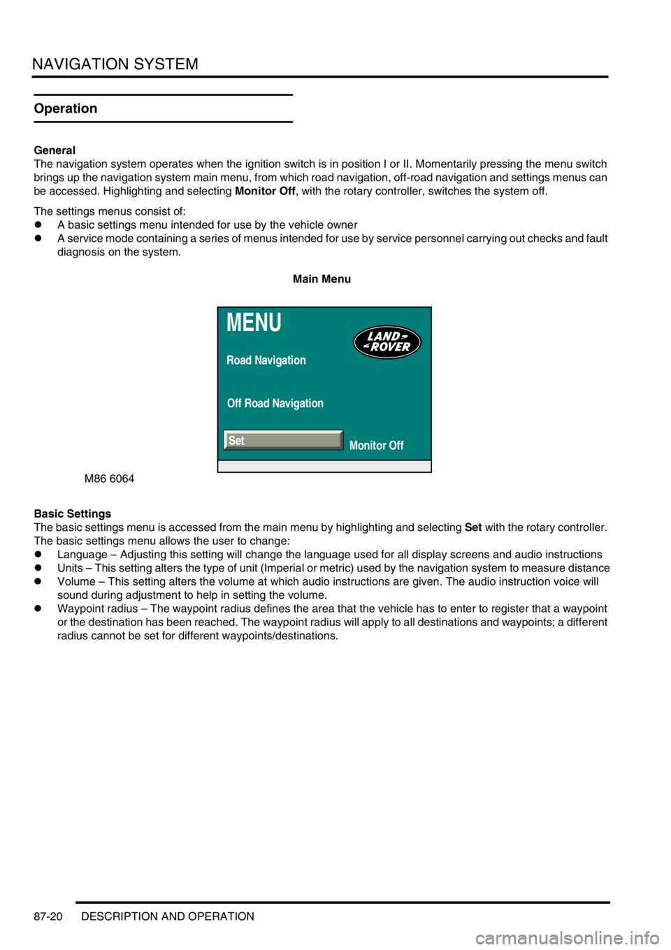
The navigation system operates when the ignition switch is in position I or II. Momentarily pressing the menu switch
brings up the navigation system main menu, from which road navigation, off-road navigation and settings menus can
be accessed. Highlighting and selecting Monitor Off, with the rotary controller, switches the system off.
The settings menus consist of:
lA basic settings menu intended for use by the vehicle owner
lA service mode containing a series of menus intended for use by service personnel carrying out checks and fault
diagnosis on the system.
Main Menu
Basic Settings
The basic settings menu is accessed from the main menu by highlighting and selecting Set with the rotary controller.
The basic settings menu allows the user to change:
lLanguage – Adjusting this setting will change the language used for all display screens and audio instructions
lUnits – This setting alters the type of unit (Imperial or metric) used by the navigation system to measure distance
lVolume – This setting alters the volume at which audio instructions are given. The audio instruction voice will
sound during adjustment to help in setting the volume.
lWaypoint radius – The waypoint radius defines the area that the vehicle has to enter to register that a waypoint
or the destination has been reached. The waypoint radius will apply to all destinations and waypoints; a different
radius cannot be set for different waypoints/destinations.
MENU
Road Navigation
Off Road Navigation
Monitor Off
M86 6064
Set
Page 1474 of 1529
NAVIGATION SYSTEM
DESCRIPTION AND OPERATION 87-21
Basic Settings Menu
Service Mode
The service mode is accessed from the basic settings menu, by pushing and holding the menu switch until the service
mode menu is displayed. On the service mode menu, various checks can be selected using the rotary controller.
Pushing the menu switch again returns the system to the main menu.
The service mode has four main functions:
lTo check that components are fitted and to determine their hardware/software levels
lTo perform a quick 'health check' of the major input signals to the system
lTo check for correct operation of the control switches
lTo check the status of the GPS reception.
Service Mode Menu
SET
Units Language
D
km
110y 220y 550ymilesGB Other
Volume
Wp. radius
- 2
M86 6065
M86 6066
ON-BOARD MONITOR
NAVIGATION / GRAPHIC
ELEMENT
VIDEO MODULE
GPS
Service Mode
SENSOR TEST
Page 1475 of 1529

NAVIGATION SYSTEM
87-22 DESCRIPTION AND OPERATION
On-Board Monitor (Display Unit)
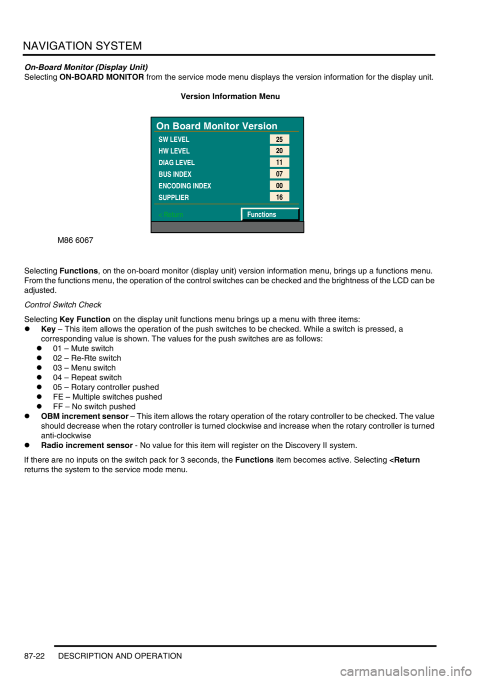
Selecting ON-BOARD MONITOR from the service mode menu displays the version information for the display unit.
Version Information Menu
Selecting Functions, on the on-board monitor (display unit) version information menu, brings up a functions menu.
From the functions menu, the operation of the control switches can be checked and the brightness of the LCD can be
adjusted.
Control Switch Check
Selecting Key Function on the display unit functions menu brings up a menu with three items:
lKey – This item allows the operation of the push switches to be checked. While a switch is pressed, a
corresponding value is shown. The values for the push switches are as follows:
l01 – Mute switch
l02 – Re-Rte switch
l03 – Menu switch
l04 – Repeat switch
l05 – Rotary controller pushed
lFE – Multiple switches pushed
lFF – No switch pushed
lOBM increment sensor – This item allows the rotary operation of the rotary controller to be checked. The value
should decrease when the rotary controller is turned clockwise and increase when the rotary controller is turned
anti-clockwise
lRadio increment sensor - No value for this item will register on the Discovery II system.
If there are no inputs on the switch pack for 3 seconds, the Functions item becomes active. Selecting
returns the system to the service mode menu.
M86 6067
On Board Monitor Version
SW LEVEL
HW LEVEL
DIAG LEVEL
BUS INDEX
ENCODING INDEX
SUPPLIER
< Return25
20
11
07
00
16
Functions