Page 1007 of 1529
SEATS
76-5-10 DESCRIPTION AND OPERATION
Heated seat block diagram (electric
seats)
1Passenger compartment fuse box
2Left seat heater switch
3Left seat heater module
4Left seat cushion heater element
5Left seat squab heater element 6Right seat heater switch
7Right seat heater module
8Right seat cushion heater element
9Right seat squab heater element
Page 1035 of 1529
SUNROOF
76-6-4 DESCRIPTION AND OPERATION
System block diagram
1Passenger compartment fuse box
2BCU
3Sunroof ECU
4Front sunroof switch
5Front sunroof motor and microswitch6Rear sunroof - front switch
7Rear sunroof isolation switch
8Rear sunroof - rear switch
9Rear sunroof motor and microswitch
Page 1080 of 1529

PANEL REPAIRS
PROCEDURES 77-2-13
PROCEDURES
General welding precautions
General
For ease of reference, the diagrams on the following pages show only the type of weld used in repair where it varies
from that used in production.
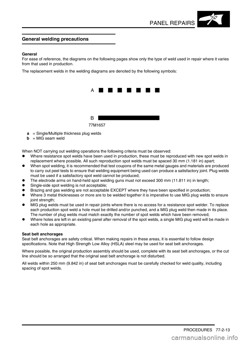
The replacement welds in the welding diagrams are denoted by the following symbols:
a = Single/Multiple thickness plug welds
b = MIG seam weld
When NOT carrying out welding operations the following criteria must be observed:
lWhere resistance spot welds have been used in production, these must be reproduced with new spot welds in
replacement where possible. All such reproduction spot welds must be spaced 30 mm (1.181 in) apart;
lWhen spot welding, it is recommended that test coupons of the same metal gauges and materials are produced
to carry out peel tests to ensure that welding equipment being used can produce a satisfactory joint. Plug welds
must be used if a satisfactory spot weld cannot be produced;
lThe electrode arms on hand-held spot welding guns must not exceed 300 mm (11.811 in) in length;
lSingle-side spot welding is not acceptable;
lBrazing and gas welding are not acceptable EXCEPT where they have been specified in production;
lWhere 3 metal thicknesses or more are to be welded together it is imperative to use MIG plug welds to ensure
joint strength;
lMIG plug welds must be used in repair joints where there is no access for a resistance spot welder. To replace
each production spot weld a hole must be drilled and/or punched, and a MIG plug weld then made in its place.
The number of plug welds must match exactly the number of spot welds which have been removed;
lWhere holes are left in an existing panel after removal of the spot welds, a single MIG plug weld will be made in
each hole as appropriate.
Seat belt anchorages
Seat belt anchorages are safety critical. When making repairs in these areas, it is essential to follow design
specifications. Note that High Strength Low Alloy (HSLA) steel may be used for seat belt anchorages.
Where possible, the original production assembly should be used, complete with its seat belt anchorages, or the cut
line should be so arranged that the original seat belt anchorage is not disturbed.
All welds within 250 mm (9.842 in) of seat belt anchorages must be carefully checked for weld quality, including
spacing of spot welds.
Page 1241 of 1529
WIPERS AND WASHERS
84-6 DESCRIPTION AND OPERATION
Wipers and washers block diagram
Page 1327 of 1529
ALARM SYSTEM AND HORN
86-4-4 DESCRIPTION AND OPERATION
Alarm system block diagram
1Body Control Unit (BCU)
2Remote handset
3Receiver
4Fuel cut off switch
5Ignition switch
6Central door locking switch
7Volumetric sensors
8Bonnet activated alarm switch
9Drivers door key lock/unlock switches
10Door latch switches 11Fuel flap release switch
12Intelligent Driver Module (IDM)
13Battery Backed Up Sounder (BBUS)
14Alarm sounder
15Vehicle horns
16Direction indicators
17Door lock actuators
18Engine Control Module (ECM)
19Starter motor
Page 1354 of 1529
WINDOWS
DESCRIPTION AND OPERATION 86-5-1
WINDOWS DESCRIPTION AND OPERAT ION
Electric windows block diagram
1Passenger compartment fusebox
2BCU
3LH front window switch
4LH front window motor
5RH front window switch
6RH front window motor
7Rear window lift relay8Centre console LH rear window switch
9LH rear door window switch
10LH rear door window motor
11Centre console RH rear window switch
12RH rear door window switch
13RH rear door window motor
14Rear window isolation switch
Page 1369 of 1529
IN CAR ENTERTAINMENT
86-6-2 DESCRIPTION AND OPERATION
Base and mid line ICE system control
diagram
1Fusible link
2Battery power supply fuse
3Remote radio control switches (if fitted)
4Radio cassette
5Telephone system interface6Speakers
7Amplifier AM/FM aerial
8AM/FM aerial
9Auxiliary power supply fuse
10Auxiliary relay
Page 1370 of 1529
IN CAR ENTERTAINMENT
DESCRIPTION AND OPERATION 86-6-3
High line ICE system control diagram
1Fusible link
2Battery power supply fuse
3Remote radio control switches
4Radio cassette
5CD-autochanger
6Telephone system interface
7Speed signal from SLABS ECU
8Speakers
9Power amplifier10Auxiliary power supply fuse
11Auxiliary relay
12Radio headphone amplifier RH rear
13Radio headphone amplifier LH rear
14Amplifier FM aerial
15FM aerial
16Amplifier AM/FM aerial
17AM/FM aerial