1999 LAND ROVER DISCOVERY lock
[x] Cancel search: lockPage 731 of 1529

STEERING
57-38 REPAIRS
Seal - output shaft - steering box
$% 57.10.17
Remove
1.Remove steering box:
lFor V8 models:
+ STEERING, REPAIRS, Power
steering box - V8.
lFor LHD diesel models:
+ STEERING, REPAIRS, Power
steering box - LHD - diesel.
lFor RHD diesel models:
+ STEERING, REPAIRS, Steering
box - RHD - diesel.
2.Secure steering box in vice.
3.Release lock washer from drop arm nut.
4.Loosen but do not remove nut securing drop
arm.
5.Using LRT-57-012, release drop arm.
6.Remove nut and discard lock washer.
7.Remove drop arm. 8.Mark position of rack adjuster.
9.Remove Allen screw securing rack adjuster
and loosen adjuster one turn.
10.Remove 4 bolts securing output shaft assembly
and remove output shaft assembly. Remove
and discard 'O' ring from end cover.
11.Remove seal shield and circlip.
12.Remove seal and spacer.
Page 732 of 1529

STEERING
REPAIRS 57-39
Refit
1.Clean seal recess, output shaft, end cover and
mating face.
2.Lubricate new end cover 'O' ring with clean
PAS fluid. Fit 'O' ring to end cover.
3.Position output shaft, fit bolts and tighten to 88
Nm (65 lbf.ft).
4.Tighten rack adjuster one turn, align marks and
secure with Allen screw.
5.Lubricate new output shaft seal with clean PAS
fluid.
6.Fit seal using LRT-57-504.
7.Fit spacer, circlip and seal shield.
8.Clean drop arm and steering box splines.
9.Ensure steering box is in the central position.
Align and fit drop arm to output shaft and
secure with new lock washer and nut. Tighten
nut to 240 Nm (177 lbf.ft).
10.Secure lock washer to drop arm nut.
11.Fit steering box.
lFor V8 models:
+ STEERING, REPAIRS, Power
steering box - V8.
lFor LHD diesel models:
+ STEERING, REPAIRS, Power
steering box - LHD - diesel.
lFor RHD diesel models:
+ STEERING, REPAIRS, Steering
box - RHD - diesel.
Pump - power steering - V8
$% 57.20.14
Remove
1.Remove auxiliary drive belt.
+ CHARGING AND STARTING,
REPAIRS, Belt - auxiliary drive.
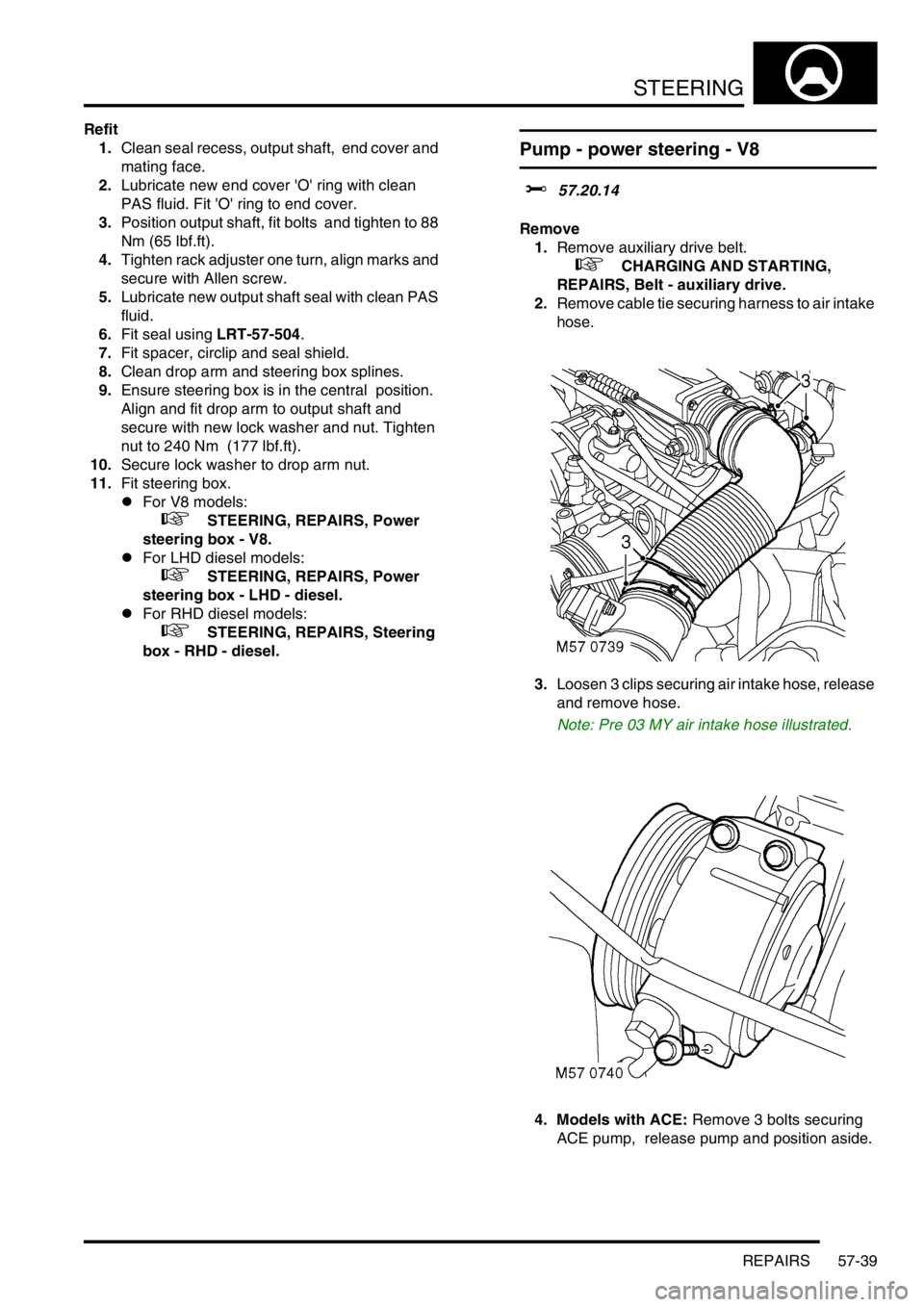
2.Remove cable tie securing harness to air intake
hose.
3.Loosen 3 clips securing air intake hose, release
and remove hose.
Note: Pre 03 MY air intake hose illustrated.
4. Models with ACE: Remove 3 bolts securing
ACE pump, release pump and position aside.
Page 736 of 1529

STEERING
REPAIRS 57-43
Steering column assembly and lock
$% 57.40.01
Remove
1.Remove steering column intermediate shaft.
+ STEERING, REPAIRS, Shaft -
intermediate and universal joint - steering
column.
2.Remove rotary coupler.
+ RESTRAINT SYSTEMS, REPAIRS,
Rotary coupler.
3.Open fascia lower access panel.
4.Remove steering column nacelle.
+ STEERING, REPAIRS, Nacelle -
steering column.
5.Disconnect multiplug and illumination bulb
from passive coil and remove passive coil.
6.Disconnect 2 multiplugs from wiper switch
assembly. 7.Disconnect 2 multiplugs from light switch
assembly.
8.Loosen screw and remove switch assembly.
9.Disconnect ignition switch multiplug.
10.Disconnect multiplug from ignition switch
housing.
11.Release harness from column clip.
Page 737 of 1529

STEERING
57-44 REPAIRS
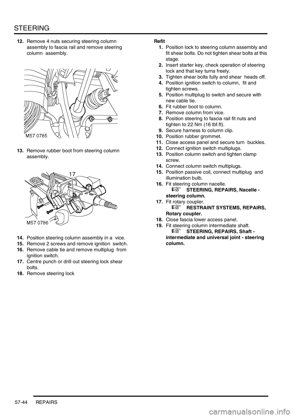
12.Remove 4 nuts securing steering column
assembly to fascia rail and remove steering
column assembly.
13.Remove rubber boot from steering column
assembly.
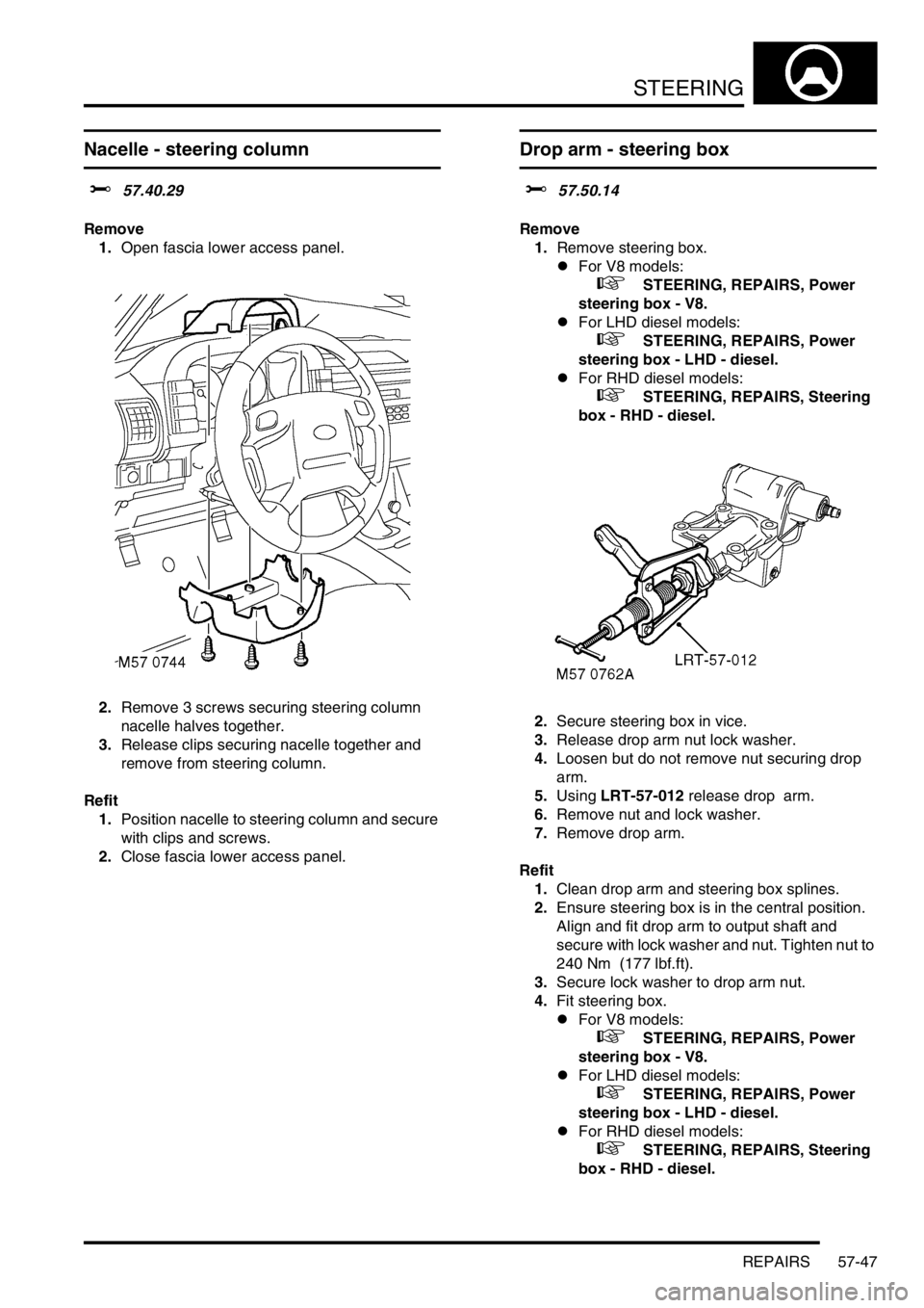
14.Position steering column assembly in a vice.
15.Remove 2 screws and remove ignition switch.
16.Remove cable tie and remove multiplug from
ignition switch.
17.Centre punch or drill out steering lock shear
bolts.
18.Remove steering lockRefit
1.Position lock to steering column assembly and
fit shear bolts. Do not tighten shear bolts at this
stage.
2.Insert starter key, check operation of steering
lock and that key turns freely.
3.Tighten shear bolts fully and shear heads off.
4.Position ignition switch to column, fit and
tighten screws.
5.Position multiplug to switch and secure with
new cable tie.
6.Fit rubber boot to column.
7.Remove column from vice.
8.Position steering to fascia rail fit nuts and
tighten to 22 Nm (16 lbf.ft).
9.Secure harness to column clip.
10.Position rubber grommet.
11.Close access panel and secure turn buckles.
12.Connect ignition switch multiplugs.
13.Position column switch and tighten clamp
screw.
14.Connect column switch multiplugs.
15.Position passive coil, connect multiplug and
illumination bulb.
16.Fit steering column nacelle.
+ STEERING, REPAIRS, Nacelle -
steering column.
17.Fit rotary coupler.
+ RESTRAINT SYSTEMS, REPAIRS,
Rotary coupler.
18.Close fascia lower access panel.
19.Fit steering column intermediate shaft.
+ STEERING, REPAIRS, Shaft -
intermediate and universal joint - steering
column.
Page 740 of 1529

STEERING
REPAIRS 57-47
Nacelle - steering column
$% 57.40.29
Remove
1.Open fascia lower access panel.
2.Remove 3 screws securing steering column
nacelle halves together.
3.Release clips securing nacelle together and
remove from steering column.
Refit
1.Position nacelle to steering column and secure
with clips and screws.
2.Close fascia lower access panel.
Drop arm - steering box
$% 57.50.14
Remove
1.Remove steering box.
lFor V8 models:
+ STEERING, REPAIRS, Power
steering box - V8.
lFor LHD diesel models:
+ STEERING, REPAIRS, Power
steering box - LHD - diesel.
lFor RHD diesel models:
+ STEERING, REPAIRS, Steering
box - RHD - diesel.
2.Secure steering box in vice.
3.Release drop arm nut lock washer.
4.Loosen but do not remove nut securing drop
arm.
5.Using LRT-57-012 release drop arm.
6.Remove nut and lock washer.
7.Remove drop arm.
Refit
1.Clean drop arm and steering box splines.
2.Ensure steering box is in the central position.
Align and fit drop arm to output shaft and
secure with lock washer and nut. Tighten nut to
240 Nm (177 lbf.ft).
3.Secure lock washer to drop arm nut.
4.Fit steering box.
lFor V8 models:
+ STEERING, REPAIRS, Power
steering box - V8.
lFor LHD diesel models:
+ STEERING, REPAIRS, Power
steering box - LHD - diesel.
lFor RHD diesel models:
+ STEERING, REPAIRS, Steering
box - RHD - diesel.
Page 745 of 1529

STEERING
57-52 REPAIRS
Steering wheel
$% 57.60.01.30
Remove
1.Remove drivers airbag.
+ RESTRAINT SYSTEMS, REPAIRS,
Airbag module - drivers.
2.Disconnect horn multiplug.
3.Centralise steering wheel with road wheels in
straight ahead position.
4.Restrain steering wheel and loosen self locking
nut securing steering wheel to column.
5.Release steering wheel from column.
6.Remove and discard self locking nut.
7.Remove steering wheel.
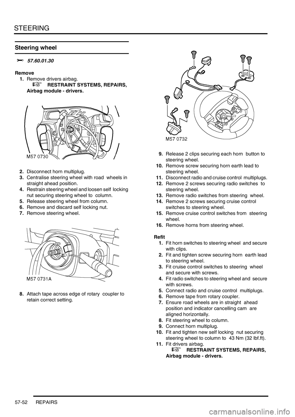
8.Attach tape across edge of rotary coupler to
retain correct setting. 9.Release 2 clips securing each horn button to
steering wheel.
10.Remove screw securing horn earth lead to
steering wheel.
11.Disconnect radio and cruise control multiplugs.
12.Remove 2 screws securing radio switches to
steering wheel.
13.Remove radio switches from steering wheel.
14.Remove 2 screws securing cruise control
switches to steering wheel.
15.Remove cruise control switches from steering
wheel.
16.Remove horns from steering wheel.
Refit
1.Fit horn switches to steering wheel and secure
with clips.
2.Fit and tighten screw securing horn earth lead
to steering wheel.
3.Fit cruise control switches to steering wheel
and secure with screws.
4.Fit radio switches to steering wheel and secure
with screws.
5.Connect radio and cruise control multiplugs.
6.Remove tape from rotary coupler.
7.Ensure road wheels are in straight ahead
position and indicator cancelling cam are
aligned horizontally.
8.Fit steering wheel to column.
9.Connect horn multiplug.
10.Fit and tighten new self locking nut securing
steering wheel to column to 43 Nm (32 lbf.ft).
11.Fit drivers airbag.
+ RESTRAINT SYSTEMS, REPAIRS,
Airbag module - drivers.
Page 751 of 1529

FRONT SUSPENSION
60-6 DESCRIPTION AND OPERATION
Panhard rod
A Panhard rod is used to ensure that the axle remains centrally located. The Panhard rod has bushes pressed into
housings at each end which provide for the attachment to the axle and chassis. One end of the Panhard rod locates
in a fabricated bracket on the axle and is secured with a bolt and locknut. The opposite end is attached to a fabricated
bracket on the chassis and is also secured with a bolt and a locknut. The Panhard rod is shaped at one end to allow
clearance for the axle casing.
The attachment bolts for the Panhard rod are coated with a clear, dry wax which reduces friction on the bolt and allows
the correct torque to be applied to the clamping of the bushes. The bolts can be re-used, but if bolt replacement is
necessary the correct bolt with the wax coating must be used.
On models from 03 Model Year, the Panhard rod is shortened by 30 mm (1.18 in). This modification was introduced
to enhance the suspension bump steer characteristics in line with other suspension improvements introduced
simultaneously. The change to the Panhard rod also required the relocation of the attachment brackets on the axle
casing and the chassis.
Torsion/Anti-roll bar
The anti-roll bars fitted differ between ACE and non-ACE vehicles. On non-ACE vehicles a conventional 'passive' anti-
roll bar is used. On ACE vehicles an 'active' torsion bar is used. Both types are attached to the front chassis cross
member with mounting rubbers and clamp plates. The clamp plates locate in brackets on the cross member and are
each secured with a bolt. Each end of the anti-roll bar is attached to an anti-roll bar link. Each link has a spherical
bearing attached at each end. One end is attached to a bracket on the axle and secured with a locknut; a washer is
installed between the spherical bearing and the bracket. The opposite end attaches through a hole in the anti-roll bar
and is secured with a locknut. On 'active' torsion bars, the RH anti-roll bar link is attached to a long arm which in turn
is attached to the torsion bar.
Passive anti-roll bar
The passive anti-roll bar is a conventional anti-roll bar which opposes axle movement, reducing the effects of lateral
forces on the vehicle body.
With the conventional 'passive' anti-roll bar, axle movement is opposed by the anti-roll bar through links attached to
the axle casing and each end of the anti-roll bar. The anti-roll bar is manufactured from 30 mm (1.18 in) diameter
spring steel bar.
Active torsion bar
+ FRONT SUSPENSION, DESCRIPTION AND OPERATION, Description - ACE.
The 'active' torsion bar is used in conjunction with the ACE system to control body roll and directional stability giving
an improved reduction of the effects of lateral forces on the vehicle body over a conventional anti-roll bar.
The torsion bar opposes axle movement by the application of a hydraulic force to oppose the lateral forces through
links attached to the axle casing and each end of the bar. The torsion bar is made from 35 mm (1.4 in) diameter spring
steel bar. One end is fitted with an arm which is operated by a hydraulic actuator to oppose cornering forces.
Page 752 of 1529

FRONT SUSPENSION
DESCRIPTION AND OPERATION 60-7
DESCRIPTION AND OPERAT ION
ACE system component layout
1Anti-roll bar link
2Suction hose
3ACE/PAS reservoir
4Return pipe
5ACE pump
6Pressure pipe
7Torsion bar - front
8Actuator hose
9Actuator hose
10Actuator
11Short arm
12Long arm
13Anti-roll bar link14Isolator and bracket (2 and 4 way) 7 off
15Pressure transducer
16Valve block
17Directional control valve 2 off
18Pressure control valve
19Long arm
20Actuator
21Anti-roll bar link
22Torsion bar - rear
23Short arm
24ACE ECU
25Accelerometer - lower
26Accelerometer - upper