1999 LAND ROVER DISCOVERY check engine
[x] Cancel search: check enginePage 153 of 1529

MAINTENANCE
10-30 PROCEDURES
Engine mountings - V8 engine
Check for security and condition
1.Check condition of Transfer box - RH mounting
rubber.
2.Check condition of Transfer box - LH mounting
rubber.
3.Check condition of Engine - LH mounting
rubber.4.Check condition of Engine - RH mounting
rubber
5.Check tightness of all mounting bolts.
+ TORQUE WRENCH SETTINGS,
Engine V8.
Page 154 of 1529

MAINTENANCE
PROCEDURES 10-31
Road/roller test
WARNING: Roller test must be restricted to 3
mph (5 km/h). If 2 wheel rolling road is to be used,
disconnect propeller shaft from the transfer box
output shaft driving the axle which is NOT on the
rolling road.
Testing
1. 2 wheel rolling road: Engage differential lock
using a 10 mm open ended spanner on flats
machined on differential lock selector
shaft.Switch on ignition and check that the
differential lock, electronic brake
distribution and hill descent warning lamps
are illuminated.
2.Check for correct operation of starter switch,
ensure engine starts correctly; leave the engine
running.
3.Check for correct operation of starter switch,
ensure engine starts correctly; leave the engine
running.
4.With vehicle stationary, turn steering from lock
to lock. Check for smooth operation and ensure
there is no undue noise from power steering
pump or drive belt.
5.Depress clutch and select all gears in turn,
check for smooth, notch free engagement.6. Check all vehicle systems for correct
operation.
7.Check for unusual engine, gearbox and
suspension noises.
8.Check braking system operation.
9.Check for smooth gear engagement.
10.Check engine performance.
11.Check operation of all instruments and warning
devices where practicable.
12.Where possible, check for correct operation of
hill descent control (HDC) mechanism. This
should not be carried out if excessive journey
time is required.
13.After road/roller test, carry out a final inspection
of vehicle, with vehicle on a ramp.
14.Check all fluid levels and top-up if necessary.
15. 2 wheel rolling road: Ensure differential lock is
disengaged and propeller shaft is connected on
completion of test. Switch on ignition and
check that differential lock, electronic brake
distribution and hill descent warning lamps
are extinguished.
Page 166 of 1529

ENGINE - V8
ADJUSTMENTS 12-2-11
ADJUST ME NTS
Engine oil pressure check
$% 12.90.09.01
Check
1.Remove oil pressure switch.
+ ENGINE - V8, REPAIRS, Switch - oil
pressure.
2.Connect pressure check kit LRT-12-052C
adaptor and gauge to oil pressure switch
position on timing gear cover.
3.Check and if necessary top up engine oil.
4.Run engine at idle speed and check that oil
pressure is within limits given.
+ GENERAL DATA, Engine - V8.
5.Switch off ignition.
6.Remove pressure check kit LRT-12-052C.
7.Clean oil spillage.
8.Fit oil pressure switch.
+ ENGINE - V8, REPAIRS, Switch - oil
pressure.
Adjust
1.If engine oil pressure is below figures given,
check condition of oil pump and/or main and
big end bearings.
Page 170 of 1529

ENGINE - V8
REPAIRS 12-2-15
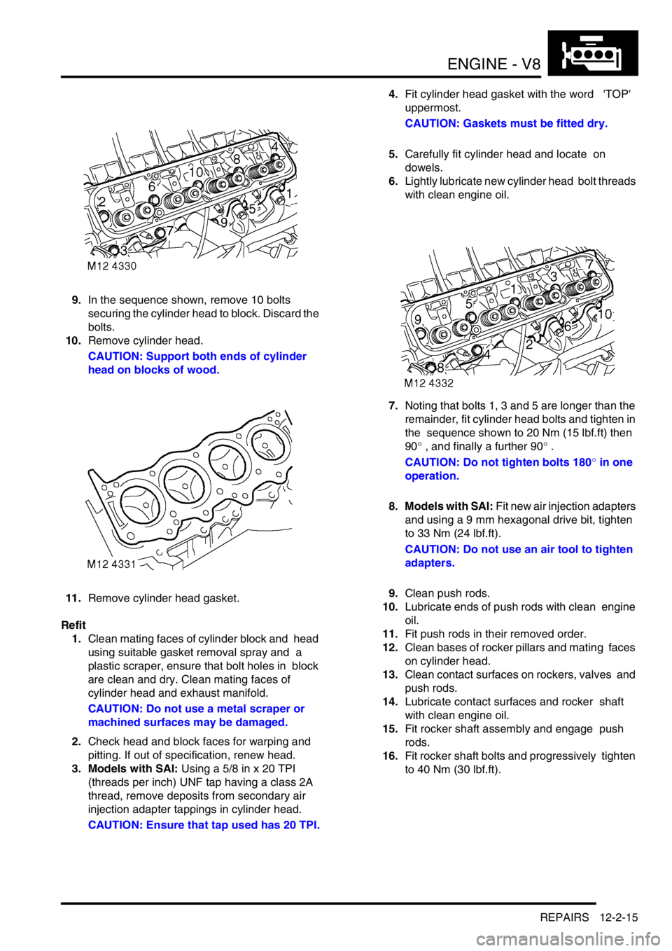
9.In the sequence shown, remove 10 bolts
securing the cylinder head to block. Discard the
bolts.
10.Remove cylinder head.
CAUTION: Support both ends of cylinder
head on blocks of wood.
11.Remove cylinder head gasket.
Refit
1.Clean mating faces of cylinder block and head
using suitable gasket removal spray and a
plastic scraper, ensure that bolt holes in block
are clean and dry. Clean mating faces of
cylinder head and exhaust manifold.
CAUTION: Do not use a metal scraper or
machined surfaces may be damaged.
2.Check head and block faces for warping and
pitting. If out of specification, renew head.
3. Models with SAI: Using a 5/8 in x 20 TPI
(threads per inch) UNF tap having a class 2A
thread, remove deposits from secondary air
injection adapter tappings in cylinder head.
CAUTION: Ensure that tap used has 20 TPI.4.Fit cylinder head gasket with the word 'TOP'
uppermost.
CAUTION: Gaskets must be fitted dry.
5.Carefully fit cylinder head and locate on
dowels.
6.Lightly lubricate new cylinder head bolt threads
with clean engine oil.
7.Noting that bolts 1, 3 and 5 are longer than the
remainder, fit cylinder head bolts and tighten in
the sequence shown to 20 Nm (15 lbf.ft) then
90° , and finally a further 90° .
CAUTION: Do not tighten bolts 180° in one
operation.
8. Models with SAI: Fit new air injection adapters
and using a 9 mm hexagonal drive bit, tighten
to 33 Nm (24 lbf.ft).
CAUTION: Do not use an air tool to tighten
adapters.
9.Clean push rods.
10.Lubricate ends of push rods with clean engine
oil.
11.Fit push rods in their removed order.
12.Clean bases of rocker pillars and mating faces
on cylinder head.
13.Clean contact surfaces on rockers, valves and
push rods.
14.Lubricate contact surfaces and rocker shaft
with clean engine oil.
15.Fit rocker shaft assembly and engage push
rods.
16.Fit rocker shaft bolts and progressively tighten
to 40 Nm (30 lbf.ft).
Page 173 of 1529

ENGINE - V8
12-2-18 REPAIRS
13.Remove cylinder head gasket.
Refit
1.Clean mating faces of cylinder block and head
using suitable gasket removal spray and a
plastic scraper, ensure that bolt holes in block
are clean and dry. Clean mating faces of
cylinder head and exhaust manifold.
CAUTION: Do not use a metal scraper or
machined surfaces may be damaged.
2.Check head and block faces for warping and
pitting. If out of specification, renew head.
3. Models with SAI: Using a 5/8 in x 20 TPI
(threads per inch) UNF tap having a class 2A
thread, remove deposits from secondary air
injection adapter tappings in cylinder head.
CAUTION: Ensure that tap used has 20 TPI.
4.Fit cylinder head gasket with the word 'TOP'
uppermost.
CAUTION: Gasket must be fitted dry.
5.Carefully fit cylinder head and locate on
dowels.
6.Lightly lubricate new cylinder head bolt threads
with clean engine oil. 7.Noting that bolts 1, 3 and 5 are longer than the
remainder, fit bolts and tighten in the sequence
shown to 20 Nm (15 lbf.ft) then 90°, and finally
a further 90°.
CAUTION: Do not tighten bolts 180° in one
operation.
8. Models with SAI: Fit new air injection adapters
and using a 9 mm hexagonal drive bit, tighten
to 33 Nm (24 lbf.ft).
CAUTION: Do not use an air tool to tighten
adapters.
9.Clean push rods.
10.Lubricate ends of push rods with clean engine
oil.
11.Fit push rods in their removed order.
12.Clean bases of rocker pillars and mating faces
on cylinder head.
13.Clean contact surfaces on rockers, valves and
push rods.
14.Lubricate contact surfaces and rocker shaft
with clean engine oil.
15.Fit rocker shaft assembly and engage push
rods.
16.Fit rocker shaft bolts and progressively tighten
to 40 Nm (30 lbf.ft).
17.Position alternator mounting bracket, fit bolts
and tighten to 40 Nm (30 lbf.ft).
18.Position auxiliary drive belt tensioner, fit bolt
and tighten to 45 Nm (33 lbf.ft).
19.Connect ht leads to spark plugs in their fitted
order.
20. Using new gaskets, fit exhaust manifold to
cylinder head. Fit bolts and using sequence
shown, tighten initially to 15 Nm (11 lbf.ft), then
finally tighten to 36 Nm (28 lbf.ft).
21. RH drive models: Fit brake servo heat shield.
+ MANIFOLDS AND EXHAUST
SYSTEMS - V8, REPAIRS, Heat shield -
brake servo - Without Secondary Air
Injection.
22.Position engine earth lead, fit bolt and tighten to
22 Nm (16 lbf.ft).
23.Fit inlet manifold gasket.
+ MANIFOLDS AND EXHAUST
SYSTEMS - V8, REPAIRS, Gasket - inlet
manifold - lower.
Page 188 of 1529

ENGINE - V8
REPAIRS 12-2-33
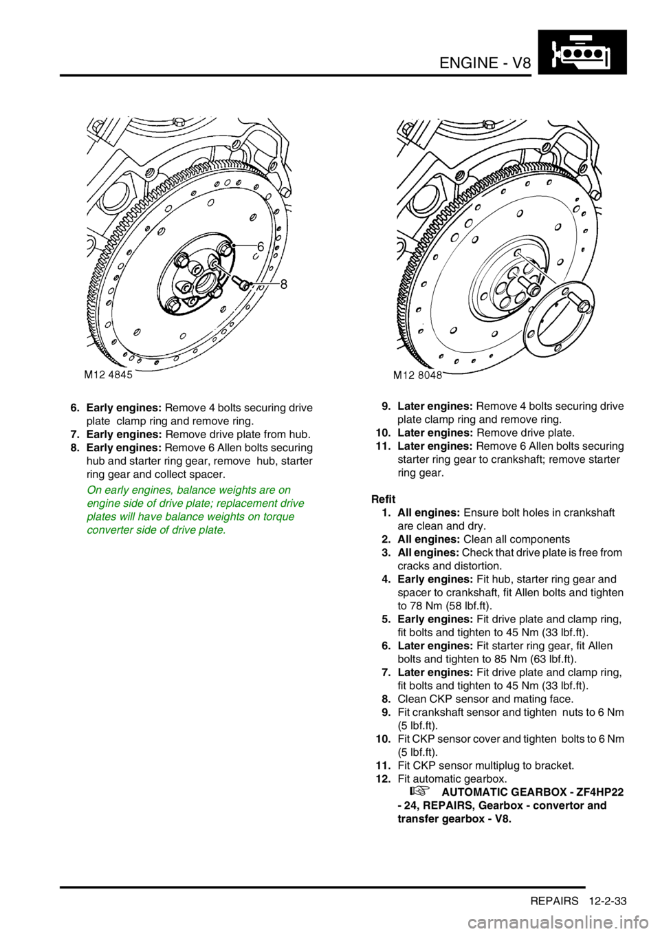
6. Early engines: Remove 4 bolts securing drive
plate clamp ring and remove ring.
7. Early engines: Remove drive plate from hub.
8. Early engines: Remove 6 Allen bolts securing
hub and starter ring gear, remove hub, starter
ring gear and collect spacer.
On early engines, balance weights are on
engine side of drive plate; replacement drive
plates will have balance weights on torque
converter side of drive plate.9. Later engines: Remove 4 bolts securing drive
plate clamp ring and remove ring.
10. Later engines: Remove drive plate.
11. Later engines: Remove 6 Allen bolts securing
starter ring gear to crankshaft; remove starter
ring gear.
Refit
1. All engines: Ensure bolt holes in crankshaft
are clean and dry.
2. All engines: Clean all components
3. All engines: Check that drive plate is free from
cracks and distortion.
4. Early engines: Fit hub, starter ring gear and
spacer to crankshaft, fit Allen bolts and tighten
to 78 Nm (58 lbf.ft).
5. Early engines: Fit drive plate and clamp ring,
fit bolts and tighten to 45 Nm (33 lbf.ft).
6. Later engines: Fit starter ring gear, fit Allen
bolts and tighten to 85 Nm (63 lbf.ft).
7. Later engines: Fit drive plate and clamp ring,
fit bolts and tighten to 45 Nm (33 lbf.ft).
8.Clean CKP sensor and mating face.
9.Fit crankshaft sensor and tighten nuts to 6 Nm
(5 lbf.ft).
10.Fit CKP sensor cover and tighten bolts to 6 Nm
(5 lbf.ft).
11.Fit CKP sensor multiplug to bracket.
12.Fit automatic gearbox.
+ AUTOMATIC GEARBOX - ZF4HP22
- 24, REPAIRS, Gearbox - convertor and
transfer gearbox - V8.
Page 190 of 1529

ENGINE - V8
REPAIRS 12-2-35
Filter - oil
$% 12.60.04
Remove
1.Clean area around filter head and place a
container beneath engine.
2.Using a strap wrench, unscrew and discard
filter.
Refit
1.Clean mating face of filter head.
2.Lubricate sealing ring of new filter with clean
engine oil.
3.Fit filter and tighten by hand until it seats then
tighten a further half turn.
4.Start and run engine to check for leaks.
5.Stop engine, wait a few minutes, then check oil
level.
6.Top up engine oil.
Strainer - oil pick-up
$% 12.60.20
Remove
1.Remove sump gasket.
+ ENGINE - V8, REPAIRS, Gasket -
sump.
2.Remove 2 bolts and one nut securing oil pick-
up strainer.
3.Remove oil pick-up strainer.
4.Collect spacer from stud.
5.Remove and discard 'O'ring.
Refit
1.Clean oil pick up strainer and 'O' ring recess.
2.Lubricate and fit new 'O' ring.
3.Locate spacer on stud.
4.Position oil pick-up strainer, fit bolts and tighten
to 10 Nm (8 lbf.ft). Fit nut and tighten to 22 Nm
(16 lbf.ft).
5.Fit new sump gasket.
+ ENGINE - V8, REPAIRS, Gasket -
sump.
Page 205 of 1529

ENGINE - V8
12-2-50 OVERHAUL
Reassembly
1.Ensure both seal location and running surface
on crankshaft are clean. Ensure that bolt holes
in crankshaft are clean and dry.
2.Lubricate replacement oil seal with engine oil.
3.Lubricate seal guide LRT-12-095 with engine
oil and position guide to crankshaft.
4.Fit new seal squarely onto crankshaft and
remove guide LRT-12-095.
5.Fit seal into location using tools LRT-12-091
and LRT-99-003.
6. All engines: Ensure bolt holes in crankshaft
are clean and dry.
7. All engines: Clean all components.
8. All engines: Check that drive plate is free from
cracks and distortion.
9. Early engines: Fit hub, starter ring gear and
spacer to crankshaft, tighten Allen bolts to 78
Nm (58 lbf.ft).
10. Early engines: Fit drive plate and clamp ring,
tighten bolts to 45 Nm (35 lbf.ft).
11. Later engines: Fit starter ring gear, fit Allen
bolts and tighten to 85 Nm (63 lbf.ft).
12. Later engines: Fit drive plate and clamp ring,
fit bolts and tighten to 45 Nm (33 lbf.ft).
13.Fit CKP sensor.
+ ENGINE MANAGEMENT SYSTEM -
V8, REPAIRS, Sensor - crankshaft position
(CKP).
Seal - crankshaft - rear - manual models
$% 12.21.20.01
Disassembly
1.Restrain flywheel.
2.Working in sequence, loosen and remove 6
bolts securing clutch cover to flywheel.
3.Remove clutch cover.
4.Remove clutch plate.
5.Remove CKP sensor.
+ ENGINE MANAGEMENT SYSTEM -
V8, REPAIRS, Sensor - crankshaft position
(CKP).
6.Remove 6 bolts securing flywheel.
7.Remove flywheel.