1999 LAND ROVER DISCOVERY air condition
[x] Cancel search: air conditionPage 62 of 1529

GENERAL INFORMATION
03-27
Body Repairs
General
Body shells are of welded construction and bolted to
a chassis frame. Front and rear sections of the shell
are designed as 'energy absorbing' zones. This
means they are designed to deform progressively
when subjected to impact in order to minimise the
likelihood of injury to vehicle occupants.
It is essential that design dimensions and strength
are restored in accident rectification. It is important
that neither structural weakness nor excessive local
stiffness are introduced into the vehicle during body
repair.
Repairs usually involve a combination of operations
ranging from straightening procedures to renewal of
individual panels or panel assemblies. The repairer
will determine the repair method and this decision will
take into account a balance of economics between
labour and material costs and the availability of repair
facilities in both equipment and skills. It may also
involve considerations of the vehicles' downtime,
replacement vehicle availability and repair turn-
around time.
It is expected that a repairer will select the best and
most economic repair method possible, making use
of the facilities available. The instructions given are
intended to assist a skilled body repairer by
expanding approved procedures for panel
replacement. The objective is to restore the vehicle
to a safe running condition by carrying out a repair
which is as close as is feasible to original standard.
The results should not advertise to the experienced
eye that the vehicle has been damaged, although the
repair might not be identical in all respects to the
original factory build. Commercial bodyshop repair
facilities cannot always duplicate methods of
construction used during production.
Operations covered in this Manual do not include
reference to testing the vehicle after repair. It is
essential that work is inspected and suspension
geometry checked after completion. Where
necessary a road test of the vehicle should be carried
out, particularly where safety-related items are
concerned.
Where major units have been disconnected or
removed it is necessary to ensure that fluid levels are
checked and topped up where necessary. It is also
necessary to ensure that the repaired vehicle is in a
roadworthy condition in respect of tyre pressures,
lights, washer fluid etc. Body repairs often involve the removal of mechanical
and electrical units and associated wiring. Where
necessary, refer to the relevant section of the
Workshop Manual for removal and refitting
instructions.
Taking into consideration the differences in body
styles, suspension systems and engine and
transmission layouts, the location of the following
components as applicable to a particular vehicle is
critical:
lFront suspension upper damper mountings on
RH and LH chassis longitudinals.
lFront suspension or sub frame mountings.
lEngine mountings on RH and LH chassis
longitudinals.
lRear suspension upper damper mountings on
RH and LH chassis longitudinals.
lRear suspension mountings or lower pivots.
Additional points which can be used to check
alignment and assembly are:
lInner holes in cross member - side - main floor.
lHoles in front bulkhead.
lHoles in rear longitudinals.
lHoles in rear lower panels.
Apertures for windscreen, rear screen, bonnet and
doors can be measured and checked using the
dimensional information provided and also by
offering up an undamaged component as a gauge.
Straightening
Whenever possible, structural members should be
cold straightened under tension. Do not attempt to
straighten with a single pull but rework the damaged
area using a series of pulls, releasing tension
between each stage and using the opportunity to
check alignment.
Body jig
Unless damage is limited to cosmetic panels, all
repair work to body members must be carried out on
a body jig, to ensure that impact damage has not
spread into more remote parts of the structure.
Mounting on a jig will also ensure that the
straightening and panel replacement procedures do
not cause further distortion.
If original dimensions cannot be satisfactorily
restored by these methods, damaged structural
members should be replaced. Damaged areas
should be cut away using a high speed saw, NOT an
oxy-acetylene torch.
As a rule, body dimensions are symmetrical about
the centre line. A good initial check for distortion is
therefore to measure diagonally and to investigate
apparent differences in dimensions.
Page 84 of 1529

GENERAL DATA
04-21
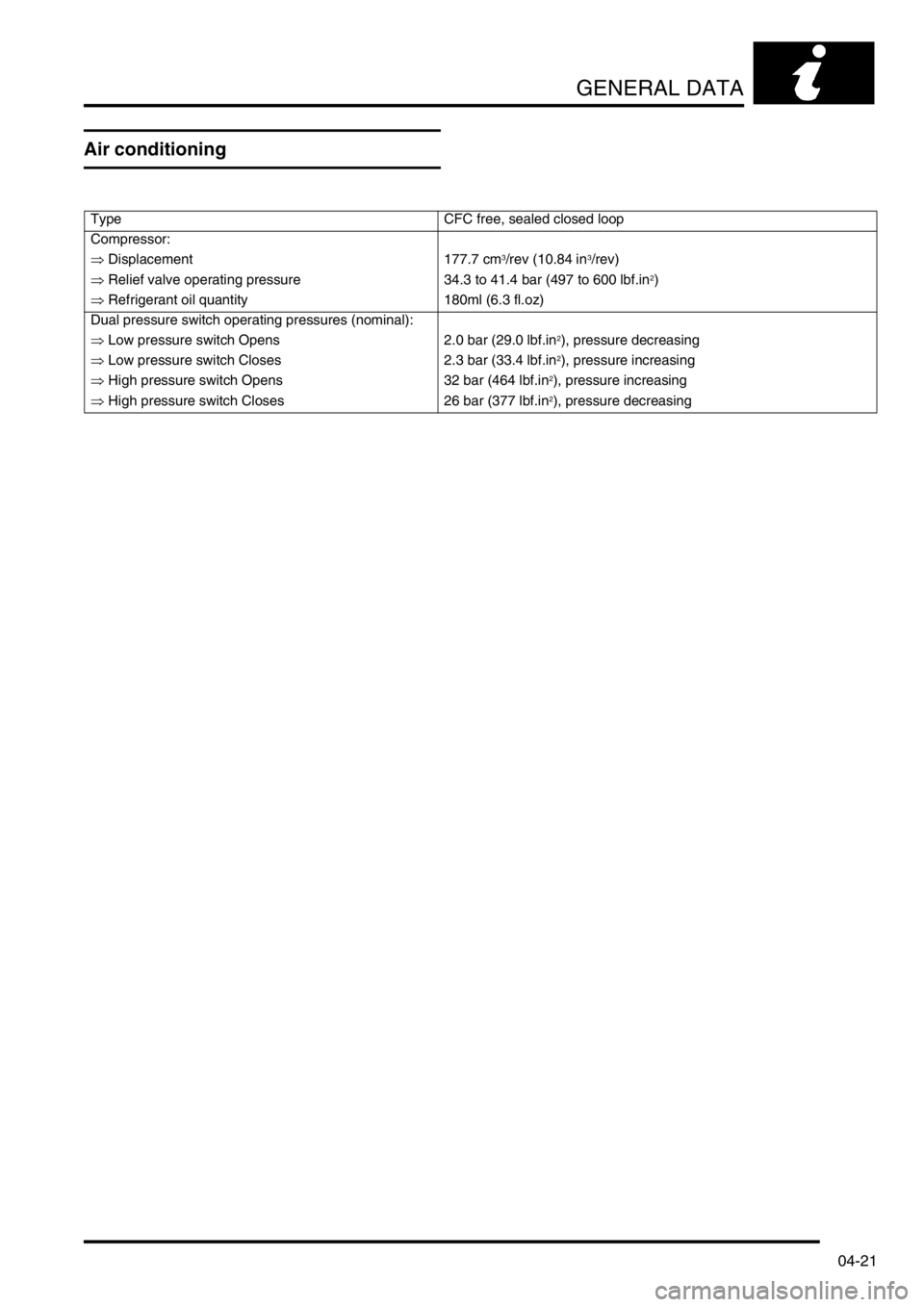
Air conditioning
Type CFC free, sealed closed loop
Compressor:
⇒ Displacement 177.7 cm
3/rev (10.84 in3/rev)
⇒ Relief valve operating pressure 34.3 to 41.4 bar (497 to 600 lbf.in
2)
⇒ Refrigerant oil quantity 180ml (6.3 fl.oz)
Dual pressure switch operating pressures (nominal):
⇒ Low pressure switch Opens 2.0 bar (29.0 lbf.in
2), pressure decreasing
⇒ Low pressure switch Closes 2.3 bar (33.4 lbf.in
2), pressure increasing
⇒ High pressure switch Opens 32 bar (464 lbf.in
2), pressure increasing
⇒ High pressure switch Closes 26 bar (377 lbf.in
2), pressure decreasing
Page 111 of 1529

TORQUE WRENCH SETTINGS
06-20
Heating and air conditioning
Wipers and washers
TORQUE DESCRIPTION METRIC IMPERIAL
Heater assembly16 Nm (12 lbf.ft)
Compressor bolts22 Nm (16 lbf.ft)
Blower motor19 Nm (14 lbf.ft)
Compressor to mounting bracket bolts 25 Nm (18 lbf.ft)
A/C pipes to compressor bolts 10 Nm (7 lbf.ft)
Condenser pipe bolt 5 Nm (3.7 lbf.ft)
Receiver drier to bracket bolts 5 Nm (3.7 lbf.ft)
Adaptor block to receiver drier bolt 5 Nm (3.7 lbf.ft)
Evaporator pipe bolts 5 Nm (3.7 lbf.ft)
Dual pressure switch to receiver drier 10 Nm (7 lbf.ft)
Air conditioning pipes to receiver drier bolts 5 Nm (3.7 lbf.ft)
TX valve pressure pipe union 22 Nm (16 lbf.ft)
Evaporator pipe to TXV valve 32 Nm (24 lbf.ft)
Evaporator assembly to body bolts 16 Nm (12 lbf.ft)
High and low pressure pipe, bolts 10 Nm (7 lbf.ft)
Fuel burning heater Torx bolts 25 Nm (18 lbf.ft)
TORQUE DESCRIPTION METRIC IMPERIAL
Link to motor spindle 7 Nm (5.2 lbf.ft)
Front motor assembly 2.5 Nm (1.8 lbf.ft)
Spindle nut 3 Nm (2.2 lbf.ft)
Wiper arm nut13 Nm (10 lbf.ft)
Page 119 of 1529

CAPACITIES, FLUIDS, LUBRICANTS AND SEALANTS
09-2
Fluids
Anti-freeze
Use Havoline Extended Life Coolant (XLC), or any
ethylene glycol based anti-freeze (containing no
methanol) with only Organic Acid Technology (OAT)
corrosion inhibitors, to protect the cooling system
CAUTION: No other anti-freeze should be used
with Havoline Extended Life Coolant.
The cooling system should be drained, flushed and
refilled with the correct amount of anti-freeze solution
at the intervals given on the Service Maintenance
Check Sheet.
After filling with anti-freeze solution, attach a warning
label to a prominent position on the vehicle stating
the type of anti-freeze contained in the cooling
system to ensure that the correct type is used for
topping-up.
Brake/Clutch fluid
Use only DOT 4 brake fluid.
PAS fluid
Use Texaco cold climate power assisted steering
fluid PSF 14315.
ACE fluid
Where ambient temperature falls below -20° C (-4°
F), use only Texaco cold climate power assisted
steering fluid PSF 14315. Where ambient
temperature remains above -20° C (-4° F), use either
Texaco cold climate power assisted steering fluid ,
Dexron 11 or Dexron 111 non-synthetic fluid.
Air conditioning
Use only refrigerant R134a.
Refrigerant oil
Use only Nippon Denso ND-oil 8.
Refrigerant oil absorbs water and must not be stored
for long periods. Do not pour unused oil back into the
container.
NOTE: The total quantity of refrigerant oil in the
system is 180 ml.
CAUTION: Do not use any other type of
refrigerant oil.
Anti-Freeze Concentration
The overall anti-freeze concentration should not fall,
by volume, below 50% to ensure that the anti-
corrosion properties of the coolant are maintained.
Anti-freeze concentrations greater than 60% are not
recommended as cooling efficiency will be impaired.
The following recommended quantities of anti-freeze
will provide frost protection to -48°C (-53°F):
Engine - TD5
Engine - V8
Concentration 50%
Amount of Anti-freeze 4 litres
Concentration 50%
Amount of Anti-freeze 6.5 litres
13.5 pts (US)
Page 121 of 1529

CAPACITIES, FLUIDS, LUBRICANTS AND SEALANTS
09-4
Gearbox oil
Manual Gearbox: Use Texaco MTF 94 oil for refill
and topping-up.
Automatic Gearbox: Use Texamatic 9226, ATF
Dexron 11D or Dexron 111 for refill and topping-up
Transfer box
Use Texaco Multi-Gear 75W/90R or oil meeting
specification API GL5.
Front and rear axles
Use Texaco Multi-Gear 75W/90R.
Air Conditioning
Use lubricating oil Nippon Denso ND-8.
General Greasing
Use Multipurpose Lithium Base Grease N.L.G.I.
consistency No. 2.
Bonnet latch
Lubricate cable and latch with oil.
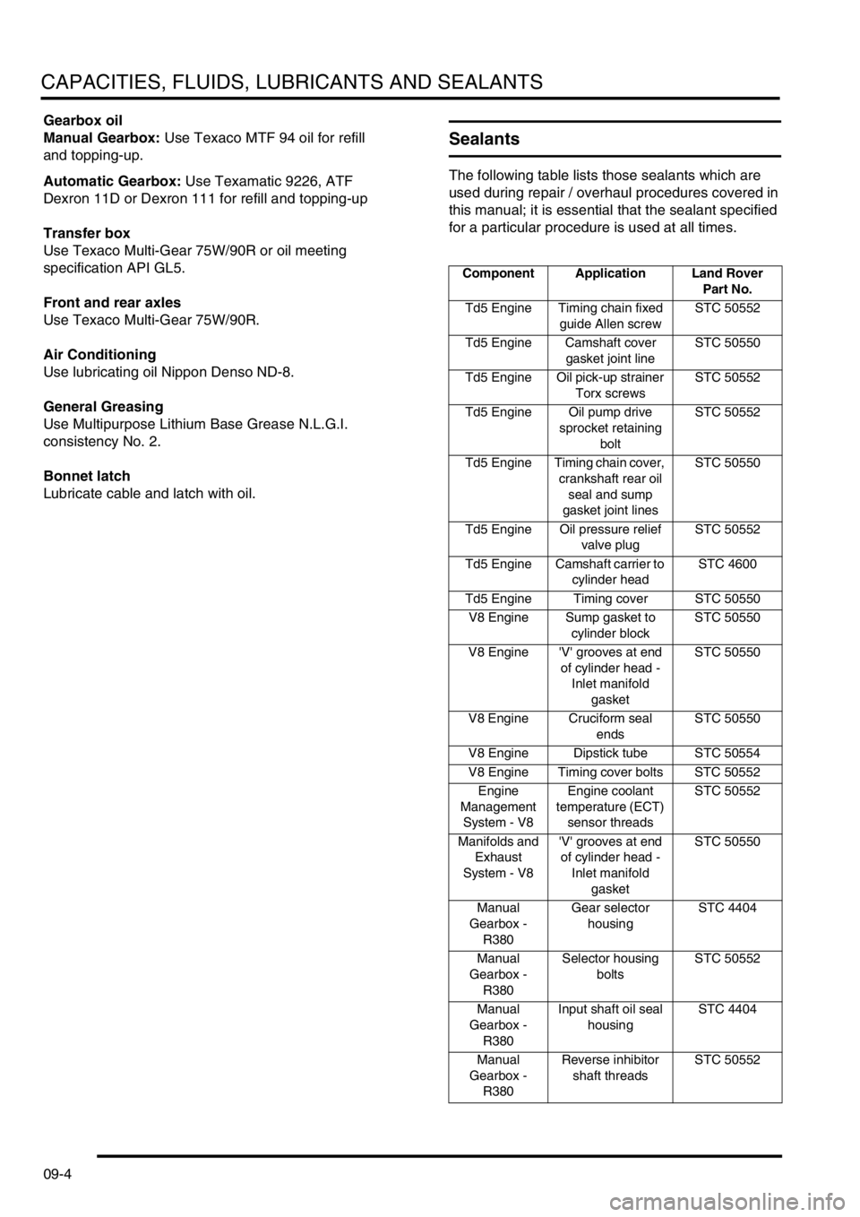
Sealants
The following table lists those sealants which are
used during repair / overhaul procedures covered in
this manual; it is essential that the sealant specified
for a particular procedure is used at all times.
Component Application Land Rover
Part No.
Td5 Engine Timing chain fixed
guide Allen screwSTC 50552
Td5 Engine Camshaft cover
gasket joint lineSTC 50550
Td5 Engine Oil pick-up strainer
Torx screwsSTC 50552
Td5 Engine Oil pump drive
sprocket retaining
boltSTC 50552
Td5 Engine Timing chain cover,
crankshaft rear oil
seal and sump
gasket joint linesSTC 50550
Td5 Engine Oil pressure relief
valve plugSTC 50552
Td5 Engine Camshaft carrier to
cylinder headSTC 4600
Td5 Engine Timing cover STC 50550
V8 Engine Sump gasket to
cylinder blockSTC 50550
V8 Engine 'V' grooves at end
of cylinder head -
Inlet manifold
gasketSTC 50550
V8 Engine Cruciform seal
endsSTC 50550
V8 Engine Dipstick tube STC 50554
V8 Engine Timing cover bolts STC 50552
Engine
Management
System - V8Engine coolant
temperature (ECT)
sensor threadsSTC 50552
Manifolds and
Exhaust
System - V8'V' grooves at end
of cylinder head -
Inlet manifold
gasketSTC 50550
Manual
Gearbox -
R380Gear selector
housingSTC 4404
Manual
Gearbox -
R380Selector housing
boltsSTC 50552
Manual
Gearbox -
R380Input shaft oil seal
housingSTC 4404
Manual
Gearbox -
R380Reverse inhibitor
shaft threadsSTC 50552
Page 132 of 1529

MAINTENANCE
PROCEDURES 10-9
Air suspension intake filter
Check
1.Check condition of filter and that filter is clean,
replace if necessary.
+ REAR SUSPENSION, REPAIRS,
Filter - intake - SLS.
Anti-freeze
Replace
1.Replace anti-freeze.
+ COOLING SYSTEM - Td5,
ADJUSTMENTS, Drain and refill.
+ COOLING SYSTEM - V8,
ADJUSTMENTS, Drain and refill.
Cooling system
Check
1.Check cooling, intercooler and heating systems
for leaks; hoses and oil pipes for security and
condition.
2.Check accessible hose clips for tightness.
3.Check coolant level, top-up if necessary.
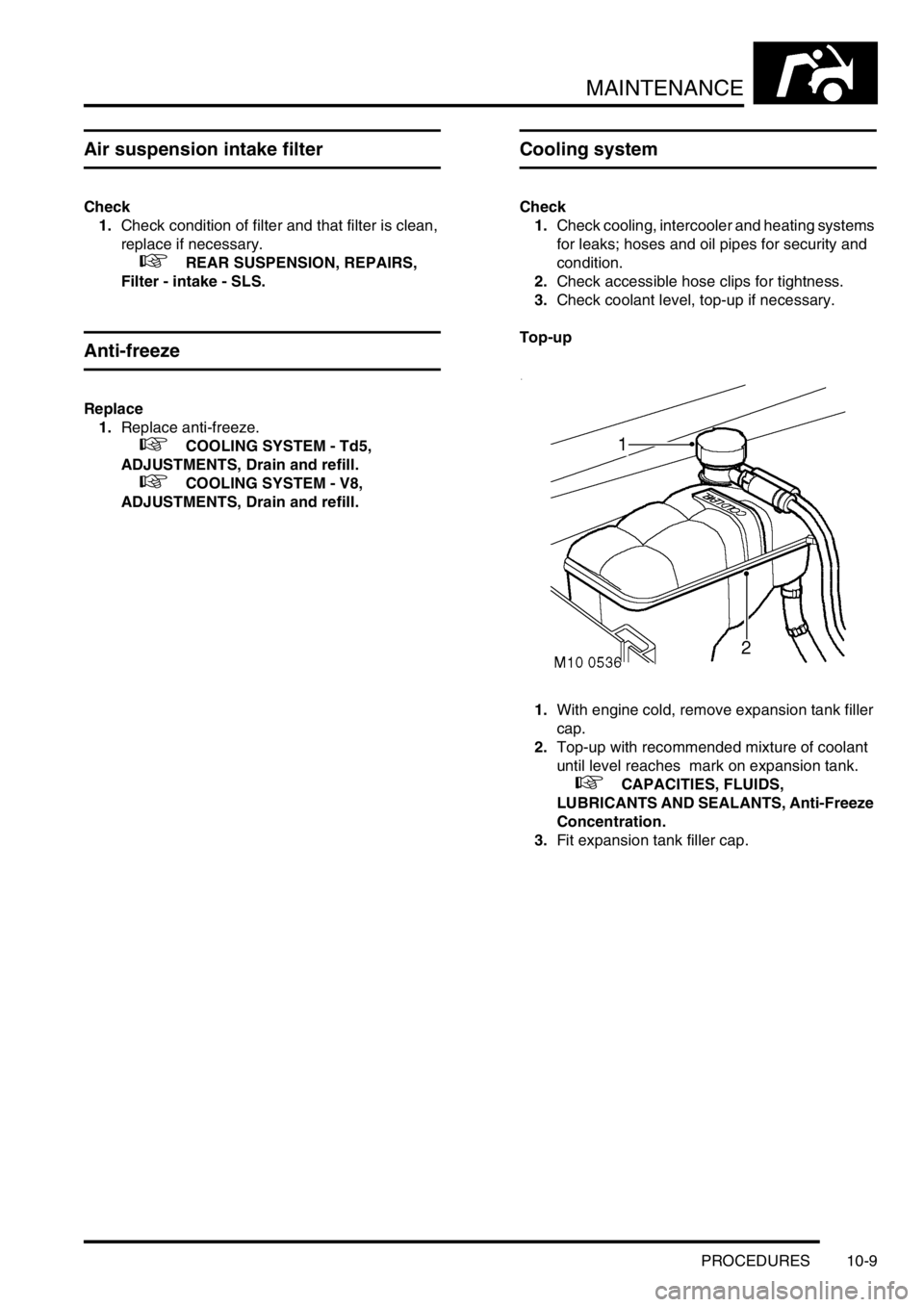
Top-up
1.With engine cold, remove expansion tank filler
cap.
2.Top-up with recommended mixture of coolant
until level reaches mark on expansion tank.
+ CAPACITIES, FLUIDS,
LUBRICANTS AND SEALANTS, Anti-Freeze
Concentration.
3.Fit expansion tank filler cap.
Page 166 of 1529

ENGINE - V8
ADJUSTMENTS 12-2-11
ADJUST ME NTS
Engine oil pressure check
$% 12.90.09.01
Check
1.Remove oil pressure switch.
+ ENGINE - V8, REPAIRS, Switch - oil
pressure.
2.Connect pressure check kit LRT-12-052C
adaptor and gauge to oil pressure switch
position on timing gear cover.
3.Check and if necessary top up engine oil.
4.Run engine at idle speed and check that oil
pressure is within limits given.
+ GENERAL DATA, Engine - V8.
5.Switch off ignition.
6.Remove pressure check kit LRT-12-052C.
7.Clean oil spillage.
8.Fit oil pressure switch.
+ ENGINE - V8, REPAIRS, Switch - oil
pressure.
Adjust
1.If engine oil pressure is below figures given,
check condition of oil pump and/or main and
big end bearings.
Page 174 of 1529

ENGINE - V8
REPAIRS 12-2-19
Gasket - rocker cover - LH
$% 12.29.40
Remove
1.Remove upper inlet manifold gasket.
+ MANIFOLDS AND EXHAUST
SYSTEMS - V8, REPAIRS, Gasket - inlet
manifold - upper - Without Secondary Air
Injection.
2. Models with air conditioning: Release 4
clips and remove fan cowl.
3. Models with air conditioning: Release
tension on auxiliary drive belt and remove belt
from air conditioning compressor. Disconnect
compressor multiplug. Remove 4 bolts
securing compressor and position compressor
aside. 4.Release ht leads from rocker cover clips.
5.Remove screw securing dip stick tube.
6.Noting fitted position of 2 long screws or multi-
hex bolts, remove and discard screws/bolts
securing rocker cover; remove rocker cover.
CAUTION: Screws/bolts must be replaced
with new 'patched' multi-hex bolts.
7.Remove and discard rocker cover gasket.