1999 LAND ROVER DISCOVERY sport mode
[x] Cancel search: sport modePage 830 of 1529

REAR SUSPENSION
DESCRIPTION AND OPERATION 64-21
Operation
Circuit diagram
1SLABS ECU
2Exhaust valve
3Restrictor
4Pressure limiting valve
5Silencer
6Inlet air filter
7Compressor
8Air dryer9Non-return valve
10RH air control valve
11RH air spring
12RH height sensor
13LH height sensor
14LH air spring
15LH air control valve
The SLS system is active when the ignition switch is in position II, when one or more doors are open and for up to
thirty minutes after all doors have been closed. If the rear axle is articulated by more than 100 mm (3.93 in), the ECU
will not activate the SLS system.
The air supply unit compressor will only operate to raise the rear of the vehicle when the engine is running, with the
exception of the remote handset operation which does not require the engine running. Three modes of SLS operation
are available; Normal Ride Height, Off-Road Mode (ORM) and Extended Mode. A fourth mode, transportation mode,
is programmed by TestBook for transport or recovery of the vehicle on a trailer.
Normal ride height
When the vehicle is stationary, a door is open and the ignition is off, the SLS system will allow the rear of the vehicle
to lower to within 20 mm of the normal ride height as load is removed from the vehicle. The SLS system will only
operate the compressor to raise the rear of the vehicle when the engine is running, unless requested using the remote
handset.
Page 832 of 1529

REAR SUSPENSION
DESCRIPTION AND OPERATION 64-23
Transportation mode
Transportation mode must be used when the vehicle is transported on a trailer and secured by the chassis. The
transportation mode can only be enabled and disabled with TestBook.
The transportation mode lowers the rear suspension onto the bump stops with the engine not running. When the
suspension is in transportation mode, the SLS warning lamp is continuously illuminated when the ignition is in position
II.
When the engine is started in transportation mode, the SLS system will raise the rear suspension until a gap of 25
mm (1 in.) exists between the bump stop and the axle. The SLS warning lamp will flash continuously while the SLS
system is raising the suspension. When the gap between the bump stop and the axle is achieved, the warning lamp
will illuminate continuously.
When TestBook is used to disable the transportation mode, the rear suspension will raise to normal ride height when
the engine is running.
Page 1347 of 1529

ALARM SYSTEM AND HORN
86-4-24 DESCRIPTION AND OPERATION
The theft deterrent LED utilises a particular flash to show the status of the following:
lAlarm armed.
lEngine immobilised.
lAlarm tampered.
lHandset low battery warning.
Transit mode
To prevent excessive battery drain during transportation to overseas markets, the vehicle is placed in a transit mode
at the end of line test.
The following functions are disabled when the vehicle is in transit mode:
lVolumetric sensors.
lPassive immobilisation.
lMobilisation of the vehicle by use of door lock.
lIgnition key interlock.
lElectric seat enable time-out with drivers door open.
To exit this mode, switch on the ignition and simultaneously hold down the heated rear window and the rear fog lamp
switch for 2 seconds.
Transit mode can be entered using Testbook.
Page 1480 of 1529

NAVIGATION SYSTEM
DESCRIPTION AND OPERATION 87-27
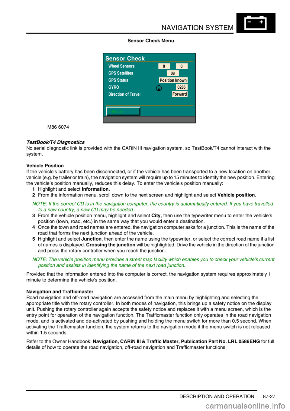
Sensor Check Menu
TestBook/T4 Diagnostics
No serial diagnostic link is provided with the CARiN III navigation system, so TestBook/T4 cannot interact with the
system.
Vehicle Position
If the vehicle’s battery has been disconnected, or if the vehicle has been transported to a new location on another
vehicle (e.g. by trailer or train), the navigation system will require up to 15 minutes to identify the new position. Entering
the vehicle’s position manually, reduces this delay. To enter the vehicle's position manually:
1Highlight and select Information.
2From the information menu, scroll down to the next screen and highlight and select Vehicle position.
NOTE: If the correct CD is in the navigation computer, the country is automatically entered. If you have travelled
to a new country, a new CD may be needed.
3From the vehicle position menu, highlight and select City, then use the typewriter menu to enter the vehicle’s
position (town, road, etc.) in the same way that you would enter a destination.
4Once the town and road names are entered, the navigation computer asks for a junction. This is the name of the
road that forms the next junction ahead of the vehicle.
5Highlight and select Junction, then enter the name using the typewriter, or select the correct road name if a list
of names is displayed. Crossing the junction will be highlighted. Drive the vehicle in the direction of the junction
and press the rotary controller when you reach the junction.
NOTE: The vehicle position menu provides a street map facility which enables you to check your vehicle’s current
position and assists in identifying the name of the next road junction.
Provided that the information entered into the computer is correct, the navigation system requires approximately 1
minute to determine the vehicle's position.
Navigation and Trafficmaster
Road navigation and off-road navigation are accessed from the main menu by highlighting and selecting the
appropriate title with the rotary controller. In both modes of navigation, this brings up a safety notice on the display
unit. Pushing the rotary controller again accepts the safety notice and replaces it with a menu screen, which is the
entry point for operation of the navigation function. The Trafficmaster function only operates in the road navigation
mode, and is activated and de-activated by pushing and holding the menu switch for more than 0.5 second. When
activating the Trafficmaster function, the system returns to the navigation mode if the menu switch is not released
within 1.5 seconds.
Refer to the Owner Handbook: Navigation, CARiN III & Traffic Master, Publication Part No. LRL 0586ENG for full
details of how to operate the road navigation, off-road navigation and Trafficmaster functions.
M86 6074
Sensor Check
Wheel Sensors
GPS Satellites
GPS Status
GYRO
Direction of Travel
< Return0
0
08
Position known
0285
Forward
Page 1484 of 1529

INSTRUMENTS
DESCRIPTION AND OPERATION 88-1
INS TRUMENTS DESCRIPTION AND OPERAT ION
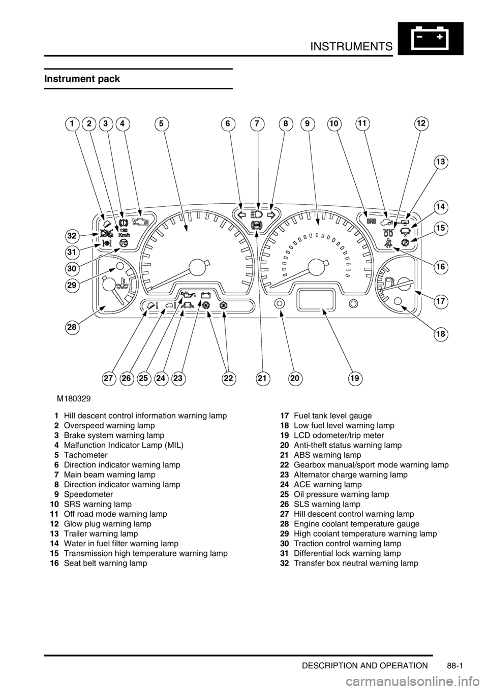
Instrument pack
1Hill descent control information warning lamp
2Overspeed warning lamp
3Brake system warning lamp
4Malfunction Indicator Lamp (MIL)
5Tachometer
6Direction indicator warning lamp
7Main beam warning lamp
8Direction indicator warning lamp
9Speedometer
10SRS warning lamp
11Off road mode warning lamp
12Glow plug warning lamp
13Trailer warning lamp
14Water in fuel filter warning lamp
15Transmission high temperature warning lamp
16Seat belt warning lamp17Fuel tank level gauge
18Low fuel level warning lamp
19LCD odometer/trip meter
20Anti-theft status warning lamp
21ABS warning lamp
22Gearbox manual/sport mode warning lamp
23Alternator charge warning lamp
24ACE warning lamp
25Oil pressure warning lamp
26SLS warning lamp
27Hill descent control warning lamp
28Engine coolant temperature gauge
29High coolant temperature warning lamp
30Traction control warning lamp
31Differential lock warning lamp
32Transfer box neutral warning lamp
Page 1489 of 1529

INSTRUMENTS
88-6 DESCRIPTION AND OPERATION
The third warning lamp pack is located in the top right-hand side of the instrument pack and contains the following
warning lamps:
lSRS warning lamp.
lSLS off road mode warning lamp.
lTrailer warning lamp.
lGlow plug warning lamp.
lWater in fuel filter warning lamp.
lSeat belt warning lamp.
lTransmission high temperature warning lamp.
The fourth warning lamp pack is located underneath the tachometer of the instrument pack contains the following
warning lamps:
lOil pressure warning lamp.
lAlternator charge warning lamp.
lHDC fault warning lamp.
lSelf Levelling Suspension (SLS) warning lamp.
lActive Cornering Enhancement (ACE) warning lamp.
lGearbox manual/sport mode warning lamps.
The serial communication link is used to allow information to travel to and from the instrument pack, and it provides
the ability to configure the instrument pack to a specific market. It also allows the instrument pack to be controlled by
TestBook for diagnostics.
There are five market specific variants of the instrument pack:
lUnited Kingdom (UK).
lNorth American Specification (NAS).
lCanada.
lAustralia.
lRest Of the World (ROW), Gulf and Japan.
The main difference between the five markets is that the speedometer will indicate road speed in mph as major figures
and km/h as minor figures, km/h as major figures and mph as minor figures or km/h only.
When TestBook is used to diagnose the instrument pack it demands each of the dials and warning lamps to operate
in-turn so a visual check of their operation can be made.
CAUTION: The instrument pack must not be stored on its face side at any time. This is because the dials have
damping fluid within them to ensure smooth operation of the dials' indicator needles. This fluid will leak out.
Speedometer
The speedometer informs the driver of the current vehicle road speed. It has a Liquid Crystal Display (LCD) to show
odometer, trip meter and, on automatic gearbox models, the selected gear. The speedometer will not show speeds
of less than 1.5 mph (2.5 km/h).
There are three different market configurations:
lNAS and UK = mph as major figures km/h as minor figures.
lCanada = km/h as major figures mph as minor figures.
lROW and Australia = km/h only.
The Self Levelling and Anti-Lock Brake System (SLABS) ECU provides the signal input for the road speed. The signal
is at 8000 pulses per mile (1.6 kilometres).
Page 1519 of 1529

INSTRUMENTS
88-36 DESCRIPTION AND OPERATION
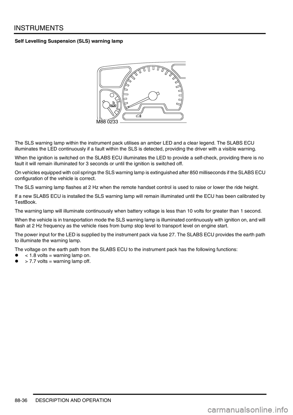
Self Levelling Suspension (SLS) warning lamp
The SLS warning lamp within the instrument pack utilises an amber LED and a clear legend. The SLABS ECU
illuminates the LED continuously if a fault within the SLS is detected, providing the driver with a visible warning.
When the ignition is switched on the SLABS ECU illuminates the LED to provide a self-check, providing there is no
fault it will remain illuminated for 3 seconds or until the ignition is switched off.
On vehicles equipped with coil springs the SLS warning lamp is extinguished after 850 milliseconds if the SLABS ECU
configuration of the vehicle is correct.
The SLS warning lamp flashes at 2 Hz when the remote handset control is used to raise or lower the ride height.
If a new SLABS ECU is installed the SLS warning lamp will remain illuminated until the ECU has been calibrated by
TestBook.
The warning lamp will illuminate continuously when battery voltage is less than 10 volts for greater than 1 second.
When the vehicle is in transportation mode the SLS warning lamp is illuminated continuously with ignition on, and will
flash at 2 Hz frequency as the vehicle rises from bump stop level to transport level on engine start.
The power input for the LED is supplied by the instrument pack via fuse 27. The SLABS ECU provides the earth path
to illuminate the warning lamp.
The voltage on the earth path from the SLABS ECU to the instrument pack has the following functions:
l< 1.8 volts = warning lamp on.
l> 7.7 volts = warning lamp off.
Page 1521 of 1529

INSTRUMENTS
88-38 DESCRIPTION AND OPERATION
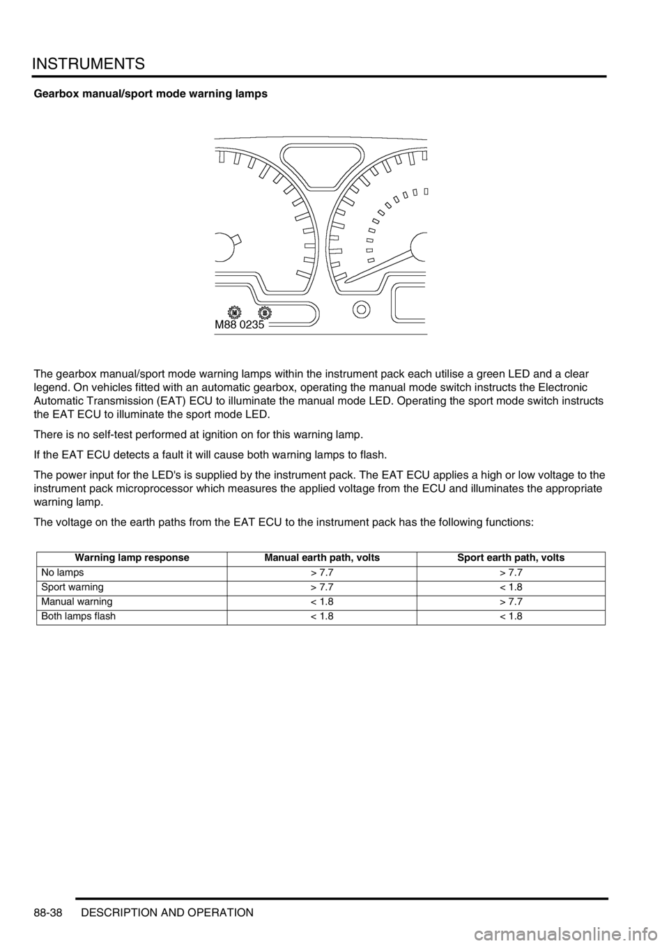
Gearbox manual/sport mode warning lamps
The gearbox manual/sport mode warning lamps within the instrument pack each utilise a green LED and a clear
legend. On vehicles fitted with an automatic gearbox, operating the manual mode switch instructs the Electronic
Automatic Transmission (EAT) ECU to illuminate the manual mode LED. Operating the sport mode switch instructs
the EAT ECU to illuminate the sport mode LED.
There is no self-test performed at ignition on for this warning lamp.
If the EAT ECU detects a fault it will cause both warning lamps to flash.
The power input for the LED's is supplied by the instrument pack. The EAT ECU applies a high or low voltage to the
instrument pack microprocessor which measures the applied voltage from the ECU and illuminates the appropriate
warning lamp.
The voltage on the earth paths from the EAT ECU to the instrument pack has the following functions:
Warning lamp response Manual earth path, volts Sport earth path, volts
No lamps > 7.7 > 7.7
Sport warning > 7.7 < 1.8
Manual warning < 1.8 > 7.7
Both lamps flash < 1.8 < 1.8