1999 LAND ROVER DISCOVERY seats
[x] Cancel search: seatsPage 1118 of 1529
PANEL REPAIRS
REPAIRS 77-2-51
Rear floor complete assembly
Remove
1.Disconnect both battery leads, negative lead
first.
2.Disconnect leads/multiplug from alternator.
3.Remove loadspace carpet.
+ INTERIOR TRIM COMPONENTS,
REPAIRS, Carpet - loadspace.
4.Remove rear seats.
+ SEATS, REPAIRS, Seat - rear.
5.Remove rear carpet.
+ INTERIOR TRIM COMPONENTS,
REPAIRS, Carpet - rear.
6.Remove rear bumper assembly.
+ EXTERIOR FITTINGS, REPAIRS,
Bumper assembly - rear - up to 03MY.
7.Remove RH and LH mud flap and brackets.
8.Remove exhaust tail pipe heatshields.
9.Remove tread plates from rear door apertures.
10.Remove rear door aperture seal.
11.Remove tail door tread plate.
12.Remove loadspace carpet retainer.
13.Remove head lining rear trim finisher.
14.Remove tail door aperture seal.
15.Remove bolts securing body to chassis.
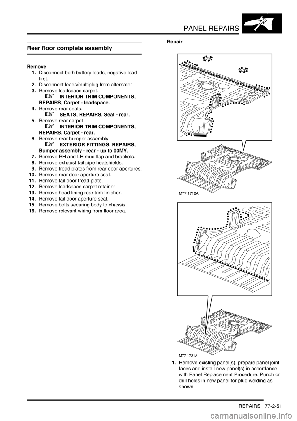
16.Remove relevant wiring from floor area.Repair
1.Remove existing panel(s), prepare panel joint
faces and install new panel(s) in accordance
with Panel Replacement Procedure. Punch or
drill holes in new panel for plug welding as
shown.
M77 1712A
M77 1721A
Page 1119 of 1529
PANEL REPAIRS
77-2-52 REPAIRS
Refit
1.Position and secure wiring.
2.Fit and tighten bolts securing body to chassis to
45 Nm (33 lbf.ft).
3.Fit tail door aperture seal.
4.Fit head lining rear trim finisher.
5.Fit loadspace carpet retainer.
6.Fit tail door tread plate.
7.Fit rear door aperture seals.
8.Fit tread plate to rear door apertures.
9.Fit exhaust tail pipe heatshields.
10.Fit mud flap bracklets and mud flaps.
11.Fit rear bumper assembly.
+ EXTERIOR FITTINGS, REPAIRS,
Bumper assembly - rear - up to 03MY.
12.Fit rear carpet.
+ INTERIOR TRIM COMPONENTS,
REPAIRS, Carpet - rear.
13.Fit rear seats.
+ SEATS, REPAIRS, Seat - rear.
14.Fit loadspace carpet.
+ INTERIOR TRIM COMPONENTS,
REPAIRS, Carpet - loadspace.
15.Connect leads/multiplug to alternator.
16.Connect battery leads, negative lead last.
Rear floor (rear section)
In this procedure, the cross member rear assembly,
cross member outer rear panel, cross member
closing rear panel, 'E' post assembly, 'E' post closing
assembly and the panel body side assembly are
replaced in conjunction with the rear floor (rear
section).
Remove
1.Disconnect both battery leads, negative lead
first.
2.Disconnect leads/multiplug from alternator.
3.Remove cross member rear assembly.
+ PANEL REPAIRS, REPAIRS, Cross
member rear assembly.
4.Remove mud flap mounting brackets.
5. LH side: Remove exhaust heatshield from rear
floor.
Repair
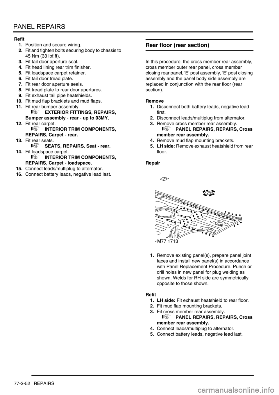
1.Remove existing panel(s), prepare panel joint
faces and install new panel(s) in accordance
with Panel Replacement Procedure. Punch or
drill holes in new panel for plug welding as
shown. Welds for RH side are symmetrically
opposite to those shown.
Refit
1. LH side: Fit exhaust heatshield to rear floor.
2.Fit mud flap mounting brackets.
3.Fit cross member rear assembly.
+ PANEL REPAIRS, REPAIRS, Cross
member rear assembly.
4.Connect leads/multiplug to alternator.
5.Connect battery leads, negative lead last.
Page 1120 of 1529
PANEL REPAIRS
REPAIRS 77-2-53
Rear floor (RH/LH section)
In this procedure, the cross member rear assembly,
cross member outer rear panel (RH/LH section),
cross member closing rear panel, 'E' post assembly,
'E' post closing assembly and the panel body side
assembly are replaced in conjunction with the rear
floor (RH/LH section).
Remove
1.Disconnect both battery leads, negative lead
first.
2.Disconnect leads/multiplug from alternator.
3.Remove cross member rear assembly.
+ PANEL REPAIRS, REPAIRS, Cross
member rear assembly.
4.Remove mud flap mounting brackets.
5. LH side: Remove exhaust heatshield from rear
floor.
Repair
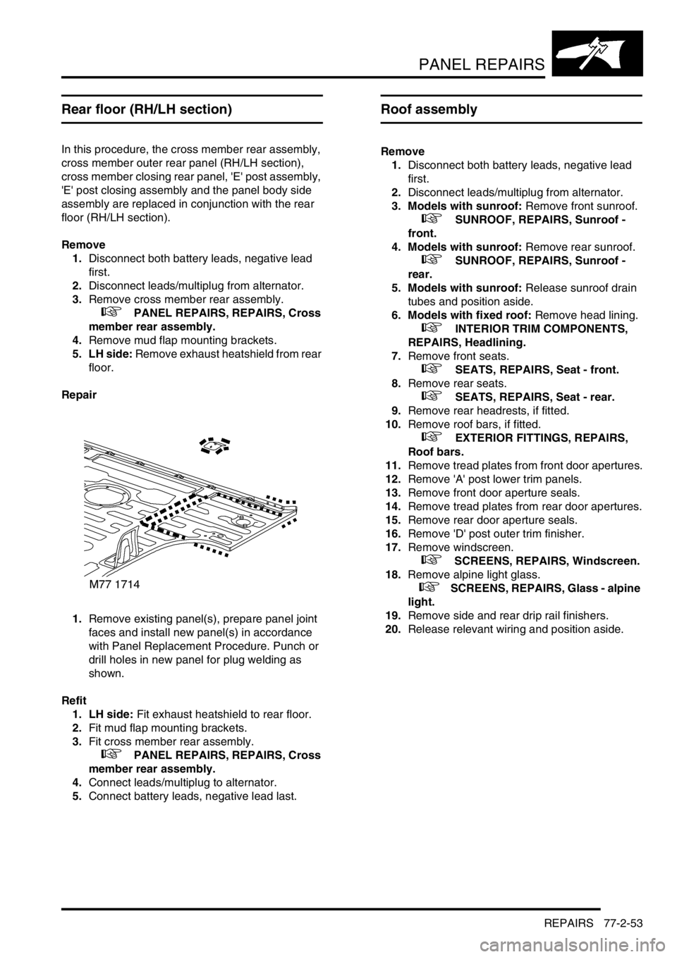
1.Remove existing panel(s), prepare panel joint
faces and install new panel(s) in accordance
with Panel Replacement Procedure. Punch or
drill holes in new panel for plug welding as
shown.
Refit
1. LH side: Fit exhaust heatshield to rear floor.
2.Fit mud flap mounting brackets.
3.Fit cross member rear assembly.
+ PANEL REPAIRS, REPAIRS, Cross
member rear assembly.
4.Connect leads/multiplug to alternator.
5.Connect battery leads, negative lead last.
Roof assembly
Remove
1.Disconnect both battery leads, negative lead
first.
2.Disconnect leads/multiplug from alternator.
3. Models with sunroof: Remove front sunroof.
+ SUNROOF, REPAIRS, Sunroof -
front.
4. Models with sunroof: Remove rear sunroof.
+ SUNROOF, REPAIRS, Sunroof -
rear.
5. Models with sunroof: Release sunroof drain
tubes and position aside.
6. Models with fixed roof: Remove head lining.
+ INTERIOR TRIM COMPONENTS,
REPAIRS, Headlining.
7.Remove front seats.
+ SEATS, REPAIRS, Seat - front.
8.Remove rear seats.
+ SEATS, REPAIRS, Seat - rear.
9.Remove rear headrests, if fitted.
10.Remove roof bars, if fitted.
+ EXTERIOR FITTINGS, REPAIRS,
Roof bars.
11.Remove tread plates from front door apertures.
12.Remove 'A' post lower trim panels.
13.Remove front door aperture seals.
14.Remove tread plates from rear door apertures.
15.Remove rear door aperture seals.
16.Remove 'D' post outer trim finisher.
17.Remove windscreen.
+ SCREENS, REPAIRS, Windscreen.
18.Remove alpine light glass.
+ SCREENS, REPAIRS, Glass - alpine
light.
19.Remove side and rear drip rail finishers.
20.Release relevant wiring and position aside.
Page 1121 of 1529
PANEL REPAIRS
77-2-54 REPAIRS
Repair
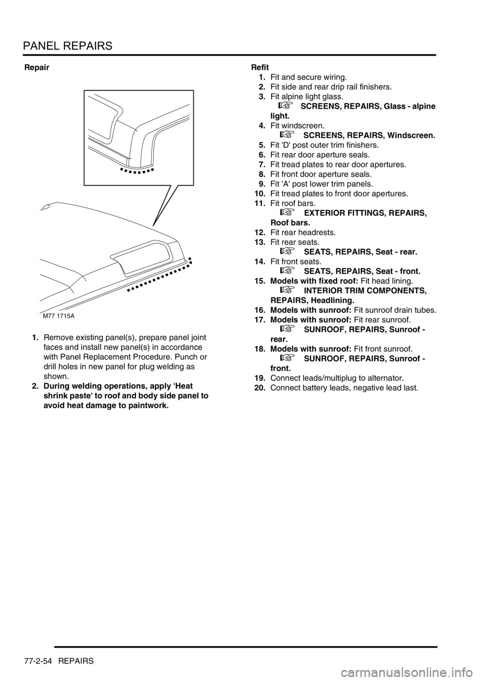
1.Remove existing panel(s), prepare panel joint
faces and install new panel(s) in accordance
with Panel Replacement Procedure. Punch or
drill holes in new panel for plug welding as
shown.
2. During welding operations, apply 'Heat
shrink paste' to roof and body side panel to
avoid heat damage to paintwork.Refit
1.Fit and secure wiring.
2.Fit side and rear drip rail finishers.
3.Fit alpine light glass.
+ SCREENS, REPAIRS, Glass - alpine
light.
4.Fit windscreen.
+ SCREENS, REPAIRS, Windscreen.
5.Fit 'D' post outer trim finishers.
6.Fit rear door aperture seals.
7.Fit tread plates to rear door apertures.
8.Fit front door aperture seals.
9.Fit 'A' post lower trim panels.
10.Fit tread plates to front door apertures.
11.Fit roof bars.
+ EXTERIOR FITTINGS, REPAIRS,
Roof bars.
12.Fit rear headrests.
13.Fit rear seats.
+ SEATS, REPAIRS, Seat - rear.
14.Fit front seats.
+ SEATS, REPAIRS, Seat - front.
15. Models with fixed roof: Fit head lining.
+ INTERIOR TRIM COMPONENTS,
REPAIRS, Headlining.
16. Models with sunroof: Fit sunroof drain tubes.
17. Models with sunroof: Fit rear sunroof.
+ SUNROOF, REPAIRS, Sunroof -
rear.
18. Models with sunroof: Fit front sunroof.
+ SUNROOF, REPAIRS, Sunroof -
front.
19.Connect leads/multiplug to alternator.
20.Connect battery leads, negative lead last.
M77 1715A
Page 1298 of 1529

BODY CONTROL UNIT
DESCRIPTION AND OPERATION 86-3-11
Programmable options
The BCU can be programmed with a number of options to satisfy specific market requirements and customer
preferences. The options can be set using TestBook.
Function Option Details
Transmission Manual The vehicle is fitted with manual transmission.
Automatic The vehicle is fitted with automatic transmission.
Front fog lamps None The vehicle is not fitted with front fog lamps.
Main The front fog lamps will operate if the headlamps are on main beam.
No main The front fog lamps will not operate if the headlamps are on main
beam.
Interlocks None The vehicle is not fitted with key, shift or transfer box interlocks.
Shift The vehicle is fitted with key, shift and transfer box interlocks.
No transfer The vehicle is fitted with key and shift interlocks, but not a transfer box
interlock.
Daylight running lamps None The vehicle is not fitted with daylight running lamps.
No main The daylight running lamps are on if the headlamp main beams are off.
No heads The daylight running lights are on with headlamp main and dipped
beams off and the gearbox not in Park.
Programmed wash/ wipe Normal The front wipers operate if the front wash is operated.
No wipe The front wipers do not operate if the front wash is operated.
Key-in warning Disabled The ignition key in audible warning is disabled.
Enabled The ignition key in audible warning is generated if the ignition key is in
and the driver's door is open.
Electric front seats None The vehicle is not fitted with electric front seats.
Normal Electric seat adjustment is available for 45 seconds after the driver's
door opens or if the ignition is on.
Ignition II Electric seat adjustment is available if the ignition is on.
Electric front windows Driver cancel The front windows will be disabled 44 seconds after the driver's door
is opened.
All cancel The front windows will be disabled 44 seconds after any door is
opened.
No cancel The front windows will be disabled when the ignition is turned off.
Heated front screen Fitted The vehicle is fitted with heated front screens.
None The vehicle is not fitted with heated front screens.
Rear windows and sunroof Driver cancel The rear windows and sunroof will be disabled 44 seconds after the
driver's door is opened.
All cancel The rear windows and sunroof will be disabled 44 seconds after any
door is opened.
No cancel The rear windows and sunroof will be disabled when the ignition
switch is turned off.
Gear position indicator
illuminationAlways The automatic gearbox selector illumination is on when the ignition is
on.
Sidelights The automatic gearbox selector illumination is on when the ignition is
on and the sidelights are off.
Hill descent control None The vehicle is not fitted with hill descent control.
Fitted The vehicle is fitted with hill descent control.
Courtesy headlamps Disabled The vehicle is not fitted with courtesy headlamps.
Enabled The vehicle is fitted with courtesy headlamps.
Odometer error warning Disabled The odometer will not flash if there is an odometer error.
Enabled The odometer will flash if there is an odometer error.
Page 1302 of 1529

BODY CONTROL UNIT
DESCRIPTION AND OPERATION 86-3-15
Electric seats
The BCU controls the logical operation of the electrically operated front seats. Two modes of operation are available:
+ SEATS, DESCRIPTION AND OPERATION, Description - electric seats.
lElectric seat adjustment is enabled if the ignition is on or the driver's door is opened for a short time period.
lElectric seat adjustment is enabled if the ignition is on and the driver's door is closed.
The seats are operated by four electric motors which control the seat cushion rear up/ down, the seat cushion front
up/ down, seat cushion forward/ rearward and seat squab recline. The electrically powered lumbar adjustment in each
seat is operated by a single motorised air pump and a solenoid located on the seat squab frame. The air pump inflates
a cushion in the seat squab and the solenoid operates a valve to deflate the cushion. The seat squab and cushion
may also contain heater elements to provide heated seat operation.
The switches for electrically operated seats are located either side of the centre console.
Direction indicators and hazard warning lamps
The direction indicator lamps are operated from a three position direction indicator switch on the left hand, steering
column stalk. The BCU only allows the lamps to work as direction indicators when the ignition switch is in position II.
The BCU also controls the lamps to operate as hazard warning lamps and as a visual warning for the anti-theft system,
in which cases all lamps flash simultaneously irrespective of the ignition switch position.
System control of the direction indicators and hazard warning lamps is provided by the BCU operating with the IDM
and two electronic relays located in the passenger compartment fuse box. The IDM and relays are integral parts of
the passenger compartment fuse box and cannot be serviced individually. The serial data bus is used for
communication of status and operation requests between the BCU, IDM and instrument pack.
The hazard warning lamps are operated from a latching pushbutton switch located on the fascia.
All direction indicator/ hazard warning lamp bulbs are rated at 5 Watts.
Headlamps
The BCU contains a feature which allow the vehicle headlamps to be turned on when the remote transmitter is
pressed (courtesy headlamps).
For markets with daylight running lamps, the BCU controls the logical operation of the daylight running lamps. Options
are daylight running lamps are on if the main beam headlamps are off, or the daylight running lamps are on with main
and dipped beam off and the gearbox not in Park.
Front fog lamps
For markets with front fog lamps fitted, the BCU controls the operation of the front fog lamps. Options can be selected
so that the fog lamps will operate with or without the headlamps on main beam.
Instrument pack
The BCU communicates with the instrument pack via a serial data bus.
+ INSTRUMENTS, DESCRIPTION AND OPERATION, Description.
lThe instrument pack provides the BCU and IDM with details of vehicle speed.
lSignals are provided from the IDM to the instrument pack and BCU when the direction indicator lamps are active.
lFor certain markets, the BCU provides a signal to the instrument pack for indicating when the transfer box is in
neutral.
lThe IDM can signal the instrument pack to illuminate a trailer warning lamp. This operates when the IDM senses
that the current drawn by the indicator circuit exceeds a preset threshold.
lThe odometer reading displayed on the instrument pack LCD screen is also stored in non volatile memory in the
BCU. Whenever the ignition is turned from position I to position II, the instrument pack and the BCU compare
their stored values.
lThe gear selector position is displayed on the instrument pack LCD screen under the direction of the BCU.
Starting
The starting system comprises a starter motor and solenoid located at the rear right hand side of the engine. A starter
relay controlled by the BCU is used to supply battery power for starter solenoid operation. The starter motor receives
its feed directly from the battery.
Page 1313 of 1529

BODY CONTROL UNIT
86-3-26 DESCRIPTION AND OPERATION
Electric seats
The BCU can be programmed to operate the electric seats according to one of three options:
lOption 1 – no electric seats.
lOption 2 – normal.
lOption 3 – operates with ignition only.
To determine when to provide an output to the passenger and drivers seat enable relay, the BCU checks the condition
of the following inputs:
lIgnition state.
lTransit mode.
lDriver's door open.
The electrically controlled seats are operated when the ignition switch is in position I or II or for a predetermined period
when the driver's door is open. If the ignition state is in crank, the seat enable relay is off. If the ignition state is off and
the driver's door open input is off, the seat enable relay is off. If the ignition state is off and the driver's door open input
is on and transit mode is on, the seat enable relay output is off.
The power supply to each seat switch pack is powered from a power seat relay located on the underside of each seat
frame. The feed from the relay is protected by a fuse located in a satellite fuse block located adjacent to the power
seat relay. The fuse block also contains two additional fuses which are used to protect the feeds to the lumbar pump
and solenoid.
With the ignition switch in position I or II or the driver's door open, the BCU provides an earth path for the coils of the
LH and RH power seat relays, energising the relays and closing the contacts. If the driver's door input signal is on for
longer than 45 seconds with the ignition switched off, the seat enable relay is switched off.
Direction indicators and hazard warning lamps
The BCU supplies reference voltages for the LH and RH indicators. When the direction indicator switch is used to
select the LH or RH indicator position, an earth path is completed which signals the BCU that a request for direction
indicator operation has been made. The BCU then communicates this request to the IDM which supplies an earth
path for the coil of the relevant relay (LH or RH indicator relay). When the relay coil is energised, the relay contacts
close and a voltage supply is provided via a resistor to the relevant direction indicators. The IDM controls the timing
of the flash operations by continually removing and restoring the earth path to the direction indicator relay coil.
The BCU checks for the following inputs for performing the logic operations associated with the direction indicator
lamps:
lIgnition state.
lRH indicators selected.
lLH indicators selected.
lHazards selected.
lInertia switch hazard request.
lOne short indicator flash request (anti-theft system arming).
lTwo short indicator flash request (superlocking).
lOne long indicator flash request (anti-theft system disarming).
lAlarm flashing indicators (anti-theft alarm triggered).
The following outputs are provided by the BCU as a result of the inputs received and the logical operations performed:
lRH indicators enable.
lLH indicators enable.
lDirection indicator left message (link to IDM).
lDirection indicator right message (link to IDM).
Direction indicator lamp failure detection
The BCU uses the following logic inputs to determine if there is a direction indicator bulb failure or if the presence of
a trailer is detected. The BCU uses the information to decide which output to enable at any particular instance:
lRight direction indicators requested.
lLeft direction indicators requested.
lRH indicators current sense.
lLH indicators current sense.
Page 1351 of 1529
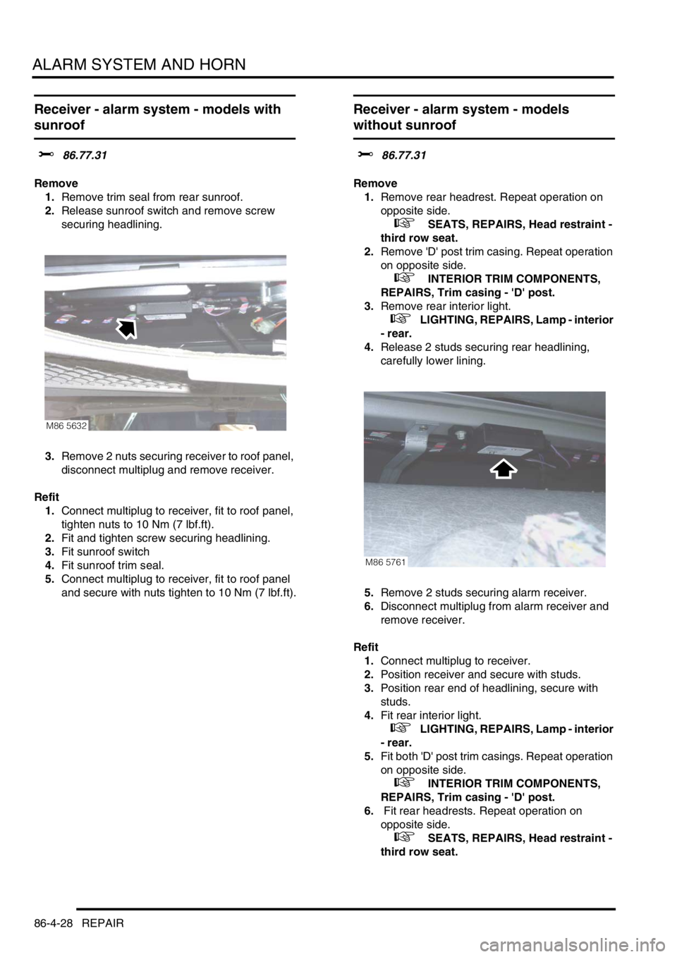
ALARM SYSTEM AND HORN
86-4-28 REPAIR
Receiver - alarm system - models with
sunroof
$% 86.77.31
Remove
1.Remove trim seal from rear sunroof.
2.Release sunroof switch and remove screw
securing headlining.
3.Remove 2 nuts securing receiver to roof panel,
disconnect multiplug and remove receiver.
Refit
1.Connect multiplug to receiver, fit to roof panel,
tighten nuts to 10 Nm (7 lbf.ft).
2.Fit and tighten screw securing headlining.
3.Fit sunroof switch
4.Fit sunroof trim seal.
5.Connect multiplug to receiver, fit to roof panel
and secure with nuts tighten to 10 Nm (7 lbf.ft).
Receiver - alarm system - models
without sunroof
$% 86.77.31
Remove
1.Remove rear headrest. Repeat operation on
opposite side.
+ SEATS, REPAIRS, Head restraint -
third row seat.
2.Remove 'D' post trim casing. Repeat operation
on opposite side.
+ INTERIOR TRIM COMPONENTS,
REPAIRS, Trim casing - 'D' post.
3.Remove rear interior light.
+ LIGHTING, REPAIRS, Lamp - interior
- rear.
4.Release 2 studs securing rear headlining,
carefully lower lining.
5.Remove 2 studs securing alarm receiver.
6.Disconnect multiplug from alarm receiver and
remove receiver.
Refit
1.Connect multiplug to receiver.
2.Position receiver and secure with studs.
3.Position rear end of headlining, secure with
studs.
4.Fit rear interior light.
+ LIGHTING, REPAIRS, Lamp - interior
- rear.
5.Fit both 'D' post trim casings. Repeat operation
on opposite side.
+ INTERIOR TRIM COMPONENTS,
REPAIRS, Trim casing - 'D' post.
6. Fit rear headrests. Repeat operation on
opposite side.
+ SEATS, REPAIRS, Head restraint -
third row seat.
M86 5632
M86 5761