1999 LAND ROVER DISCOVERY brakes
[x] Cancel search: brakesPage 903 of 1529

BRAKES
70-50 REPAIRS
Switch - Hill descent control
$% 70.70.11
Remove
1.Carefully remove switch.
2.Disconnect multiplug from switch.
3.Remove switch.
Refit
1.Connect multiplug switch.
2.Position switch and push to secure.
Switch - handbrake
$% 86.65.45
Remove
1.Remove centre console.
+ INTERIOR TRIM COMPONENTS,
REPAIRS, Console - centre - automatic
models.
+ INTERIOR TRIM COMPONENTS,
REPAIRS, Console - centre - manual
models.
2.Disconnect Lucar from handbrake warning
switch.
3.Remove clip and clevis pin securing cable to
handbrake lever.
4.Remove 2 bolts and remove handbrake lever.
5.Remove 2 screws securing switch to
handbrake lever and remove switch.
Refit
1.Fit switch to handbrake lever and tighten
screws.
2.Position handbrake lever to floor and tighten
bolts to 22 Nm (16 lbf.ft).
3.Align cable to handbrake lever and fit clevis pin
and clip.
4.Connect Lucar to handbrake switch.
5.Fit centre console.
+ INTERIOR TRIM COMPONENTS,
REPAIRS, Console - centre - automatic
models.
+ INTERIOR TRIM COMPONENTS,
REPAIRS, Console - centre - manual
models.
Page 1095 of 1529
PANEL REPAIRS
77-2-28 REPAIRS
Valance upper assembly - LH
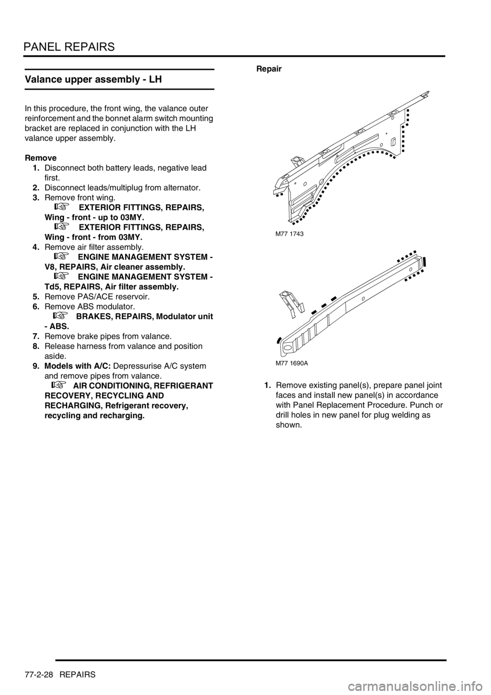
In this procedure, the front wing, the valance outer
reinforcement and the bonnet alarm switch mounting
bracket are replaced in conjunction with the LH
valance upper assembly.
Remove
1.Disconnect both battery leads, negative lead
first.
2.Disconnect leads/multiplug from alternator.
3.Remove front wing.
+ EXTERIOR FITTINGS, REPAIRS,
Wing - front - up to 03MY.
+ EXTERIOR FITTINGS, REPAIRS,
Wing - front - from 03MY.
4.Remove air filter assembly.
+ ENGINE MANAGEMENT SYSTEM -
V8, REPAIRS, Air cleaner assembly.
+ ENGINE MANAGEMENT SYSTEM -
Td5, REPAIRS, Air filter assembly.
5.Remove PAS/ACE reservoir.
6.Remove ABS modulator.
+ BRAKES, REPAIRS, Modulator unit
- ABS.
7.Remove brake pipes from valance.
8.Release harness from valance and position
aside.
9. Models with A/C: Depressurise A/C system
and remove pipes from valance.
+ AIR CONDITIONING, REFRIGERANT
RECOVERY, RECYCLING AND
RECHARGING, Refrigerant recovery,
recycling and recharging.Repair
1.Remove existing panel(s), prepare panel joint
faces and install new panel(s) in accordance
with Panel Replacement Procedure. Punch or
drill holes in new panel for plug welding as
shown.
M77 1743
M77 1690A
Page 1096 of 1529
PANEL REPAIRS
REPAIRS 77-2-29
Refit
1. Models with A/C: Fit A/C pipes and recharge
A/C system.
+ AIR CONDITIONING, REFRIGERANT
RECOVERY, RECYCLING AND
RECHARGING, Refrigerant recovery,
recycling and recharging.
2.Fit harness to valance.
3.Fit brake pipes to valance.
4.Fit ABS modulator.
+ BRAKES, REPAIRS, Modulator unit
- ABS.
5.Fit PAS/ACE reservoir, refill fluids to correct
levelsand bleed ACE system.
+ FRONT SUSPENSION,
ADJUSTMENTS, ACE hydraulic system
bleeding.
+ CAPACITIES, FLUIDS,
LUBRICANTS AND SEALANTS, Fluids.
6.Fit air filter assembly.
+ ENGINE MANAGEMENT SYSTEM -
V8, REPAIRS, Air cleaner assembly.
+ ENGINE MANAGEMENT SYSTEM -
Td5, REPAIRS, Air filter assembly.
7.Fit front wing.
+ EXTERIOR FITTINGS, REPAIRS,
Wing - front - up to 03MY.
+ EXTERIOR FITTINGS, REPAIRS,
Wing - front - from 03MY.
8.Connect leads/multiplug to alternator.
9.Connect battery leads, negative lead last.
Valance upper assembly - RH
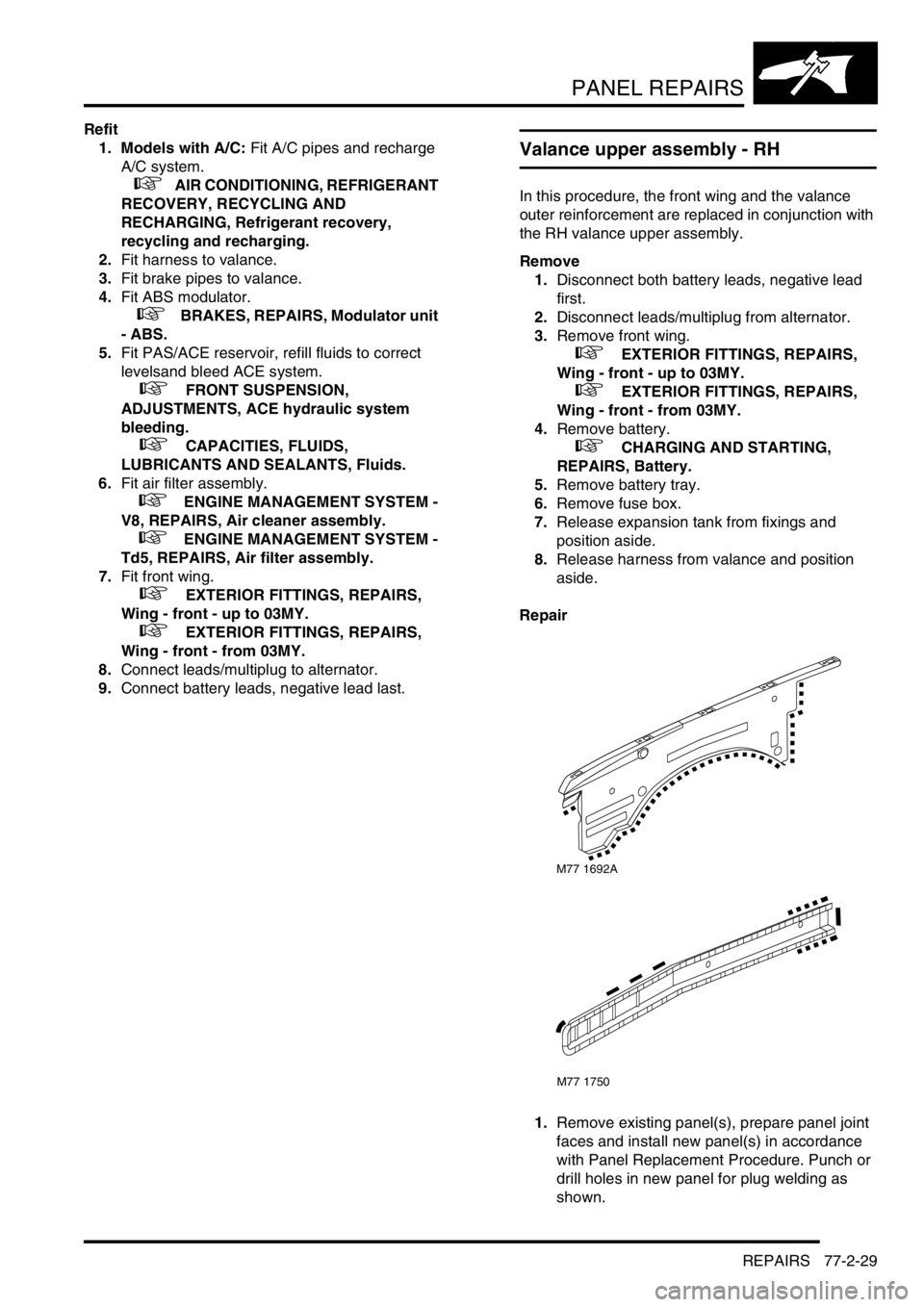
In this procedure, the front wing and the valance
outer reinforcement are replaced in conjunction with
the RH valance upper assembly.
Remove
1.Disconnect both battery leads, negative lead
first.
2.Disconnect leads/multiplug from alternator.
3.Remove front wing.
+ EXTERIOR FITTINGS, REPAIRS,
Wing - front - up to 03MY.
+ EXTERIOR FITTINGS, REPAIRS,
Wing - front - from 03MY.
4.Remove battery.
+ CHARGING AND STARTING,
REPAIRS, Battery.
5.Remove battery tray.
6.Remove fuse box.
7.Release expansion tank from fixings and
position aside.
8.Release harness from valance and position
aside.
Repair
1.Remove existing panel(s), prepare panel joint
faces and install new panel(s) in accordance
with Panel Replacement Procedure. Punch or
drill holes in new panel for plug welding as
shown.
M77 1692A
M77 1750
Page 1097 of 1529
PANEL REPAIRS
77-2-30 REPAIRS
Refit
1.Fit harness to valance.
2.Fit and secure expansion tank to fixings.
3.Fit fuse box.
4.Fit battery tray.
5.Fit battery.
+ CHARGING AND STARTING,
REPAIRS, Battery.
6.Fit front wing.
+ EXTERIOR FITTINGS, REPAIRS,
Wing - front - up to 03MY.
+ EXTERIOR FITTINGS, REPAIRS,
Wing - front - from 03MY.
7.Connect leads/multiplug to alternator.
8.Connect battery leads, negative lead last.
Valance upper assembly (front section) -
LH
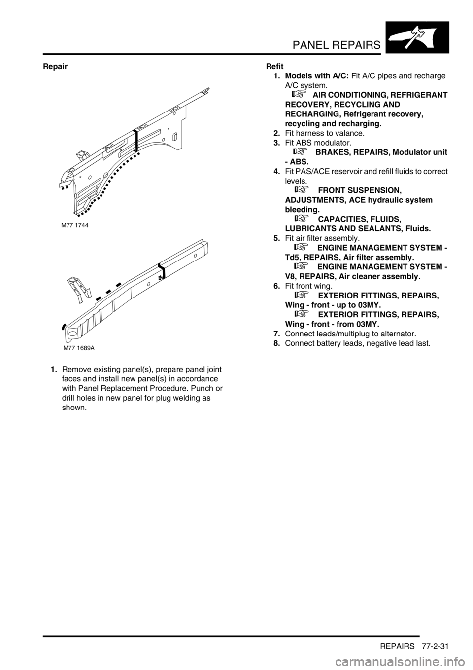
In this procedure, the front wing, the valance outer
reinforcement (front section) and the bonnet alarm
switch mounting bracket are replaced in conjunction
with the LH valance upper assembly (front section).
Remove
1.Disconnect both battery leads, negative lead
first.
2.Disconnect leads/multiplug from alternator.
3.Remove front wing.
+ EXTERIOR FITTINGS, REPAIRS,
Wing - front - up to 03MY.
+ EXTERIOR FITTINGS, REPAIRS,
Wing - front - from 03MY.
4.Remove air filter assembly.
+ ENGINE MANAGEMENT SYSTEM -
Td5, REPAIRS, Air filter assembly.
+ ENGINE MANAGEMENT SYSTEM -
V8, REPAIRS, Air cleaner assembly.
5.Remove PAS/ACE reservoir.
6.Remove ABS modulator.
+ BRAKES, REPAIRS, Modulator unit
- ABS.
7.Release harness from valance and position
aside.
8. Models with A/C: Depressurise A/C system
and remove pipes from valance.
+ AIR CONDITIONING, REFRIGERANT
RECOVERY, RECYCLING AND
RECHARGING, Refrigerant recovery,
recycling and recharging.
Page 1098 of 1529
PANEL REPAIRS
REPAIRS 77-2-31
Repair
1.Remove existing panel(s), prepare panel joint
faces and install new panel(s) in accordance
with Panel Replacement Procedure. Punch or
drill holes in new panel for plug welding as
shown.Refit
1. Models with A/C: Fit A/C pipes and recharge
A/C system.
+ AIR CONDITIONING, REFRIGERANT
RECOVERY, RECYCLING AND
RECHARGING, Refrigerant recovery,
recycling and recharging.
2.Fit harness to valance.
3.Fit ABS modulator.
+ BRAKES, REPAIRS, Modulator unit
- ABS.
4.Fit PAS/ACE reservoir and refill fluids to correct
levels.
+ FRONT SUSPENSION,
ADJUSTMENTS, ACE hydraulic system
bleeding.
+ CAPACITIES, FLUIDS,
LUBRICANTS AND SEALANTS, Fluids.
5.Fit air filter assembly.
+ ENGINE MANAGEMENT SYSTEM -
Td5, REPAIRS, Air filter assembly.
+ ENGINE MANAGEMENT SYSTEM -
V8, REPAIRS, Air cleaner assembly.
6.Fit front wing.
+ EXTERIOR FITTINGS, REPAIRS,
Wing - front - up to 03MY.
+ EXTERIOR FITTINGS, REPAIRS,
Wing - front - from 03MY.
7.Connect leads/multiplug to alternator.
8.Connect battery leads, negative lead last.
M77 1744
M77 1689A
Page 1100 of 1529
PANEL REPAIRS
REPAIRS 77-2-33
Front valance assembly - RH
Remove
1.Disconnect battery eath lead.
2.Remove front bulkhead assembly.
+ PANEL REPAIRS, REPAIRS, Front
bulkhead assembly.
3.Remove engine compartment fusebox and
related wiring.
4.Remove radiator expansion tank from
mountings and position aside.
5. Petrol models: Remove cruise control
actuator mounting bracket.
6. Diesel models: Remove EGR modulator
mounting bracket.
7. RHD models: Remove brake servo.
+ BRAKES, REPAIRS, Servo - brake.
8.Remove brake pipes from valance assembly.
9.Remove RH road wheel.
10.Remove RH front mud flap.
11.Remove insulation pad from engine bulkhead.
12.Remove windscreen side finisher.
+ EXTERIOR FITTINGS, REPAIRS,
Side finisher - windscreen.
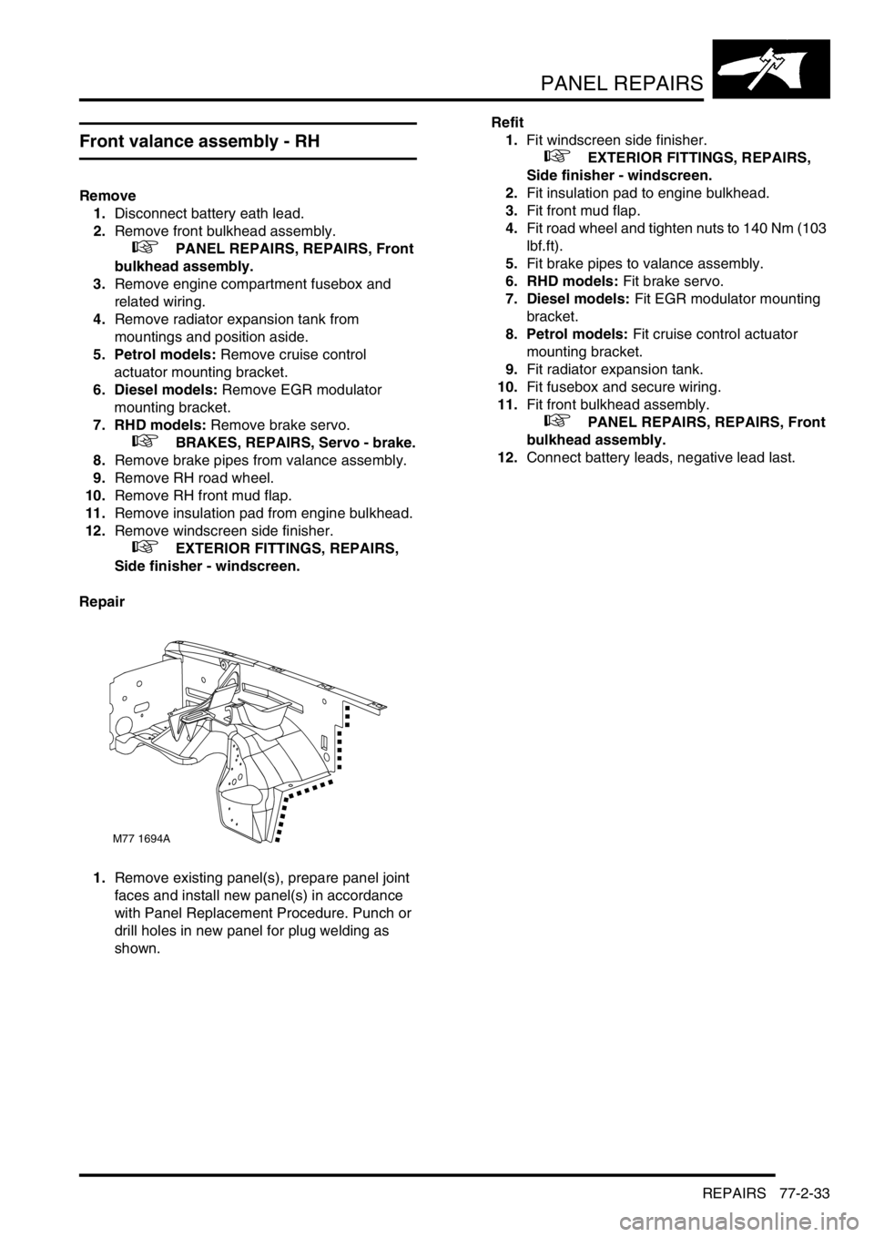
Repair
1.Remove existing panel(s), prepare panel joint
faces and install new panel(s) in accordance
with Panel Replacement Procedure. Punch or
drill holes in new panel for plug welding as
shown.Refit
1.Fit windscreen side finisher.
+ EXTERIOR FITTINGS, REPAIRS,
Side finisher - windscreen.
2.Fit insulation pad to engine bulkhead.
3.Fit front mud flap.
4.Fit road wheel and tighten nuts to 140 Nm (103
lbf.ft).
5.Fit brake pipes to valance assembly.
6. RHD models: Fit brake servo.
7. Diesel models: Fit EGR modulator mounting
bracket.
8. Petrol models: Fit cruise control actuator
mounting bracket.
9.Fit radiator expansion tank.
10.Fit fusebox and secure wiring.
11.Fit front bulkhead assembly.
+ PANEL REPAIRS, REPAIRS, Front
bulkhead assembly.
12.Connect battery leads, negative lead last.
M77 1694A
Page 1101 of 1529
PANEL REPAIRS
77-2-34 REPAIRS
Front valance assembly - LH
Remove
1.Disconnect both battery leads, negative lead
first.
2.Disconnect leads/multiplug from alternator.
3.Remove front bulkhead assembly.
+ PANEL REPAIRS, REPAIRS, Front
bulkhead assembly.
4.Remove ABS modulator unit.
+ BRAKES, REPAIRS, Modulator unit
- ABS.
5. LHD models: Remove brake servo.
+ BRAKES, REPAIRS, Servo - brake.
6.Remove brake pipes from valance assembly.
7.Remove PAS/ACE reservoir.
8. Models with A/C: Remove A/C pipes from
valance assembly.
9.Remove wiring harness from valance
assembly.
10.Remove LH front road wheel.
11.Remove LH front mud flap.
12.Remove insulation pad from engine bulkhead.
13.Remove windscreen side finisher.
+ EXTERIOR FITTINGS, REPAIRS,
Side finisher - windscreen.
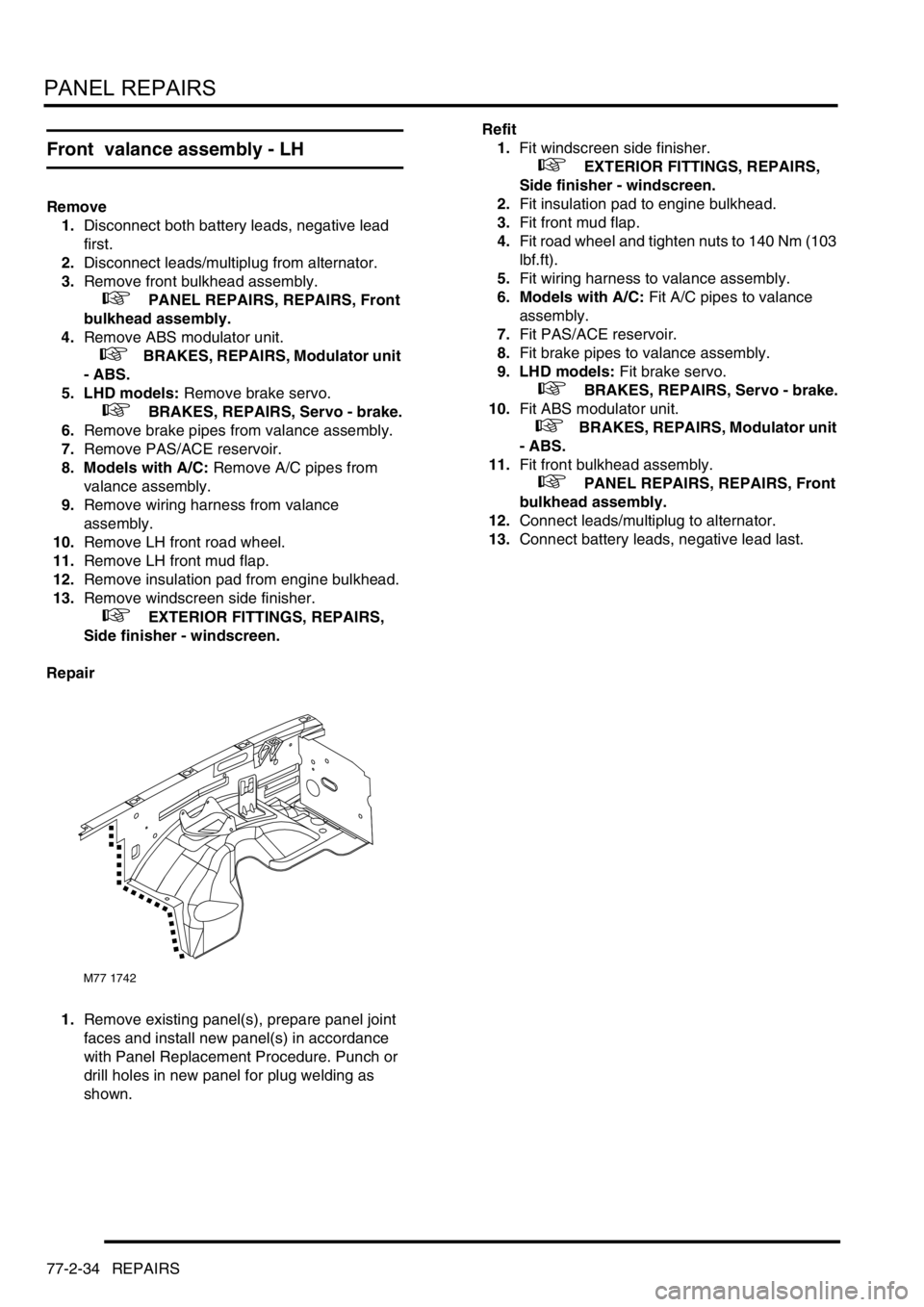
Repair
1.Remove existing panel(s), prepare panel joint
faces and install new panel(s) in accordance
with Panel Replacement Procedure. Punch or
drill holes in new panel for plug welding as
shown.Refit
1.Fit windscreen side finisher.
+ EXTERIOR FITTINGS, REPAIRS,
Side finisher - windscreen.
2.Fit insulation pad to engine bulkhead.
3.Fit front mud flap.
4.Fit road wheel and tighten nuts to 140 Nm (103
lbf.ft).
5.Fit wiring harness to valance assembly.
6. Models with A/C: Fit A/C pipes to valance
assembly.
7.Fit PAS/ACE reservoir.
8.Fit brake pipes to valance assembly.
9. LHD models: Fit brake servo.
+ BRAKES, REPAIRS, Servo - brake.
10.Fit ABS modulator unit.
+ BRAKES, REPAIRS, Modulator unit
- ABS.
11.Fit front bulkhead assembly.
+ PANEL REPAIRS, REPAIRS, Front
bulkhead assembly.
12.Connect leads/multiplug to alternator.
13.Connect battery leads, negative lead last.
M77 1742
Page 1139 of 1529
CORROSION PREVENTION AND SEALING
77-4-6 CORROSION PREVENTION
Corrosion prevention
Factory treatments
During production, vehicle bodies are treated with the following anti-corrosion materials:
lA PVC-based underbody sealer which is sprayed onto the underside of the main floor, rear floor, front and rear
wheelarches and the front valance assembly;
lAn application of cavity wax which is sprayed into the sill panels, 'A' post, 'B-C' post, fuel filler aperture, body rear
panel and the lower areas of the door panels;
lA coating of underbody wax which is applied to the entire underbody inboard of the sill vertical flanges, and
covers all moving and flexible components EXCEPT for wheels, tyres, brakes and exhaust;
lA coat of protective wax applied to the engine bay area.
Whenever body repairs are carried out, ensure the anti-corrosion materials in the affected area are repaired or
renewed as necessary using the approved materials.
+ BODY SEALING MATERIALS, MATERIALS AND APPLICATIONS, Approved materials.
Precautions during body repairs and handling
Take care when handling the vehicle in the workshop. Underbody sealers, seam sealers, underbody wax and body
panels may be damaged if the vehicle is carelessly lifted.
+ LIFTING AND TOWING, LIFTING.
Proprietary anti-corrosion treatments
The application of proprietary anti-corrosion treatments, in addition to the factory-applied treatment, could invalidate
the Corrosion Warranty and should be discouraged. This does not apply to Rover approved, compatible, preservative
waxes which may be applied on top of existing coatings.
Fitting approved accessories
When fitting accessories ensure that the vehicle's corrosion protection is not affected, either by breaking the protective
coating or by introducing a moisture trap.
Do not screw self-tapping screws directly into body panels. Fit suitable plastic inserts to the panel beforehand. Always
ensure that the edges of holes drilled into panels, chassis members and other body parts are protected with a suitable
zinc rich or acid etch primer, and follow with a protective wax coating brushed onto the surrounding area.
Do not attach painted metal surfaces of any accessory directly to the vehicle's bodywork unless suitably protected.
Where metal faces are bolted together always interpose a suitable interface material such as weldable zinc rich
primer, extruded strip, or zinc tape.
Steam cleaning and dewaxing
Due to the high temperatures generated by steam cleaning equipment, there is a risk that certain trim components
could be damaged and some adhesives and corrosion prevention materials softened or liquified.
Adjust the equipment so that the nozzle temperature does not exceed 90° C (194° F). Take care not to allow the steam
jet to dwell on one area, and keep the nozzle at least 300 mm (11.811 in) from panel surfaces.
DO NOT remove wax or lacquer from underbody or underbonnet areas during repairs. Should it be necessary to
steam clean these areas, apply a new coating of wax or underbody protection as soon as possible.
Inspections during maintenance servicing
It is a requirement of the Corrosion Warranty that the vehicle body is checked for corrosion by an authorised Land
Rover Dealer at least once a year, to ensure that the factory-applied protection remains effective.
Service Job Sheets include the following operations to check bodywork for corrosion:
lWith the vehicle on a lift, carry out visual check of underbody sealer for damage;
lWith the vehicle lowered, inspect exterior paintwork for damage and body panels for corrosion.
It will be necessary for the vehicle to be washed by the Dealer prior to inspection of bodywork if the customer has
offered the vehicle in a dirty condition.