1999 LAND ROVER DEFENDER clock
[x] Cancel search: clockPage 24 of 667

GENERAL SPECIFICATION DATA
1
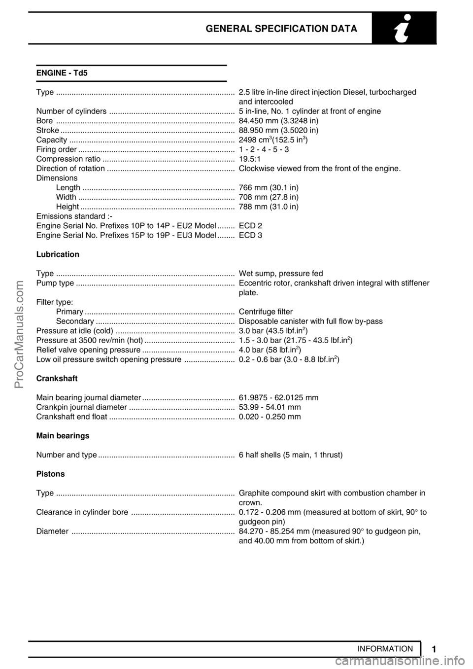
INFORMATION ENGINE - Td5
Type 2.5 litre in-line direct injection Diesel, turbocharged.................................................................................
and intercooled
Number of cylinders 5 in-line, No. 1 cylinder at front of engine.........................................................
Bore 84.450 mm (3.3248 in).................................................................................
Stroke 88.950 mm (3.5020 in)...............................................................................
Capacity 2498 cm
3(152.5 in3) ...........................................................................
Firing order 1 - 2 - 4 - 5 - 3.......................................................................
Compression ratio 19.5:1............................................................
Direction of rotation Clockwise viewed from the front of the engine...........................................................
Dimensions
Length 766 mm (30.1 in).....................................................................
Width 708 mm (27.8 in).......................................................................
Height 788 mm (31.0 in)......................................................................
Emissions standard :-
Engine Serial No. Prefixes 10P to 14P - EU2 Model ECD 2........
Engine Serial No. Prefixes 15P to 19P - EU3 Model ECD 3........
Lubrication
Type Wet sump, pressure fed.................................................................................
Pump type Eccentric rotor, crankshaft driven integral with stiffener........................................................................
plate.
Filter type:
Primary Centrifuge filter....................................................................
Secondary Disposable canister with full flow by-pass...............................................................
Pressure at idle (cold) 3.0 bar (43.5 lbf.in
2) ......................................................
Pressure at 3500 rev/min (hot) 1.5 - 3.0 bar (21.75 - 43.5 lbf.in2) .........................................
Relief valve opening pressure 4.0 bar (58 lbf.in2) ..........................................
Low oil pressure switch opening pressure 0.2 - 0.6 bar (3.0 - 8.8 lbf.in2) .......................
Crankshaft
Main bearing journal diameter 61.9875 - 62.0125 mm..........................................
Crankpin journal diameter 53.99 - 54.01 mm................................................
Crankshaft end float 0.020 - 0.250 mm.........................................................
Main bearings
Number and type 6 half shells (5 main, 1 thrust)..............................................................
Pistons
Type Graphite compound skirt with combustion chamber in.................................................................................
crown.
Clearance in cylinder bore 0.172 - 0.206 mm (measured at bottom of skirt, 90°to ...............................................
gudgeon pin)
Diameter 84.270 - 85.254 mm (measured 90°to gudgeon pin, ..........................................................................
and 40.00 mm from bottom of skirt.)
ProCarManuals.com
Page 49 of 667

07GENERAL FITTING REMINDERS
6
INFORMATION FUEL SYSTEM HOSES
CAUTION: All fuel hoses are made up of
two laminations, an armoured rubber outer
sleeve and an inner viton core. If any of
the fuel system hoses have been disconnected, it
is imperative that the internal bore is inspected to
ensure that the viton lining has not become
separated from the amoured outer sleeve. A new
hose must be fitted if separation is evident.
METRIC BOLT IDENTIFICATION
1.An ISO metric bolt or screw, made of steel and
larger than 6 mm in diameter can be identified by
either of the symbols ISO M or M embossed or
indented on top of the head.
2.In addition to marks to identify the manufacture,
the head is also marked with symbols to indicate
the strength grade, e.g. 8.8, 12.9 or 14.9, where
the first figure gives the minimum tensile
strength of the bolt material in tens of kgf/mm
2.
3.Zinc plated ISO metric bolts and nuts are
chromate passivated, a gold-bronze colour.METRIC NUT IDENTIFICATION
1.A nut with an ISO metric thread is marked on
one face or on one of the flats of the hexagon
with the strength grade symbol 8, 12 or 14.
Some nuts with a strength 4, 5 or 6 are also
marked and some have the metric symbol M on
the flat opposite the strength grade marking.
2.A clock face system is used as an alternative
method of indicating the strength grade. The
external chamfers or a face of the nut is marked
in a position relative to the appropriate hour
mark on a clock face to indicate the strength
grade.
3.A dot is used to locate the 12 O’clock position
and a dash to indicate the strength grade. If the
grade is above 12, two dots identify the 12
O’clock position.
KEYS AND KEYWAYS
1.Remove burrs from edges of keyways with a fine
file and clean thoroughly before attempting to
refit key.
2.Clean and inspect key closely; keys are suitable
for refitting only if indistinguishable from new, as
any indentation may indicate the onset of wear.
TAB WASHERS
1.Fit new washers in all places where they are
used. Always fit a new tab washer.
2.Ensure that the new tab washer is of the same
design as that replaced.
ProCarManuals.com
Page 67 of 667

10MAINTENANCE
8
MAINTENANCE FUEL FILTER ELEMENT
1.Renew fuel filter element.See FUEL SYSTEM,
Repair.FUEL FILTER SEDIMENTER - Td5
WARNING: Fuel vapour is highly
flammable and in contained speces is also
explosive and toxic. Always have a fire
extinguisher containing FOAM, CO2, GAS OR
POWDER close at hand when handling or draining
fuel.
1.Disconnect battery negative lead.
2.Position suitable container beneath fuel filter
3.Disconnect multiplug from sedimenter
4.Rotate sedimenter anti-clockwise until water
flows from drain tube.
5.Allow to drain until diesel fuel flows from drain
tube.
6.Rotate sedimenter fully clockwise.
7.Connect multiplug.
8.Reconnect battery negative lead.
ProCarManuals.com
Page 128 of 667

ENGINE
3
REPAIR
25.Using sequence shown, progressively tighten
bolts to25 Nm (18 lbf.ft).
26.Lubricate a new camshaft rear oil seal with
engine oil, fit seal using a suitable mandrel.
27.Fit rocker shaft ensuring it is located on dowel, fit
new bolts and working from the centre outwards,
tighten bolts progressively to32 Nm (24 lbf.ft).
28.Fit new’O’ring to injector harness multiplug, fit
harness and connect injector multiplugs.
29.Fit cylinder head gasket.See this Section.
30.Before refitting the camshaft cover the fuel
injector rockers must be adjusted.
31.Rotate engine clockwise until No. 1 injector lobe
is at full lift.
32.Rotate rocker adjusting screw clockwise until the
injector plunger is felt to bottom out.
33.Rotate rocker adjusting screw anti-clockwise 1
complete turn to give plunger the required bump
clearance and tighten rocker adjusting screw
locknut to16 Nm (12 lbf.ft).
34.Carry out above procedure for the remaining 4
rockers.
35.After completion of rocker adjustment, slowly
rotate engine clockwise 2 complete turns by
hand to ensure that no injectors are bottoming
out on their plungers.PULLEY - CRANKSHAFT
Service repair no - 12.21.01
Remove
1.Remove underbelly panel.See CHASSIS AND
BODY, Repair.
2.Remove radiator.See COOLING SYSTEM,
Repair.
3.Using a 15 mm ring spanner release the
auxiliary drive belt tensioner.
4.Remove auxiliary drive belt.
5.Remove 3 bolts and remove crankshaft damper.
6.PositionLRT-51-003to crankshaft pulley and
secure with 2 bolts.
7.Remove and discard crankshaft pulley bolt.
Remove crankshaft pulley.
8.Remove 2 bolts and removeLRT-51-003.
ProCarManuals.com
Page 133 of 667

12ENGINE
8
REPAIR
NOTE: Non EU3 model illustrated.
21.Loosen vacuum pipe union from cylinder head
and discard’O’ring.
22.Loosen 2 bolts and release alternator support
bracket from cylinder head.
23. Pre EU3 model:-Remove bolt securing EGR
valve pipe to cylinder head.
24. EU3 model:-Release the clips and disconnect
the coolant hoses from the EGR cooler.
25.Release clips and disconnect top hose, heater
hose and heater feed hose.
26.Remove the nut and bolt securing the cuylinder
head to the timing chain cover.
27.Rotate engine clockwise to align mark on
camshaft sprocket between coloured links on
timing chain.
28.PositionLRT-12-058through camshaft carrier to
lock camshaft.
29.PositionLRT-12-158through gearbox bell
housing to lock crankshaft.
ProCarManuals.com
Page 136 of 667

ENGINE
11
REPAIR 63. Pre EU3 model:-Fit bolt, EGR valve pipe to
cylinder head and tighten to25 Nm (18 lbf.ft).
64. EU3 model:-Connect coolant hoses to EGR
cooler and secure with clips.
65.Position air intake hose to EGR valve and
tighten clip screw.
66.Disconnect fuel hose from connector block and
connect to fuel cooler.
67.Connect fuel hoses to fuel cooler and connector
block on cylinder head.
68.Connect coolant hoses to fuel cooler and secure
clips.
69.Connect vacuum hose to EGR valve.
70.Position engine harness and connect multiplugs
and heater plug connectors.
71.Fit and tighten bolts, engine harness to camshaft
carrier.
72.Clean exhaust manifold and mating face.
73.Fit new gasket to exhaust manifold, position
turbocharger and tighten nuts to30 Nm (22 lbf.
ft).
74.Clean turbocharger feed hose bolt.
75.Position feed hose using new sealing washers,
tighten bolt to25 Nm (18 lbf.ft).
76.Position exhaust manifold heat shield, and
tighten M6 bolts to10 Nm (7 lbf.ft)and M8 bolt
to25 Nm (18 lbf.ft).
77.Position air inlet hose to turbocharger and
tighten clip screw.
78.Connect air flow meter to air filter and secure
clips.
79.Connect air flow meter multiplug.
80.Fit cooling fan.See COOLING SYSTEM,
Repair.
81.Fit camshaft cover gasket.See this Section.
82.Refill cooling system.See COOLING SYSTEM,
Adjustment.
83.Fit underbelly panel.See CHASSIS AND
BODY, Repair.ROCKER SHAFT ASSEMBLY
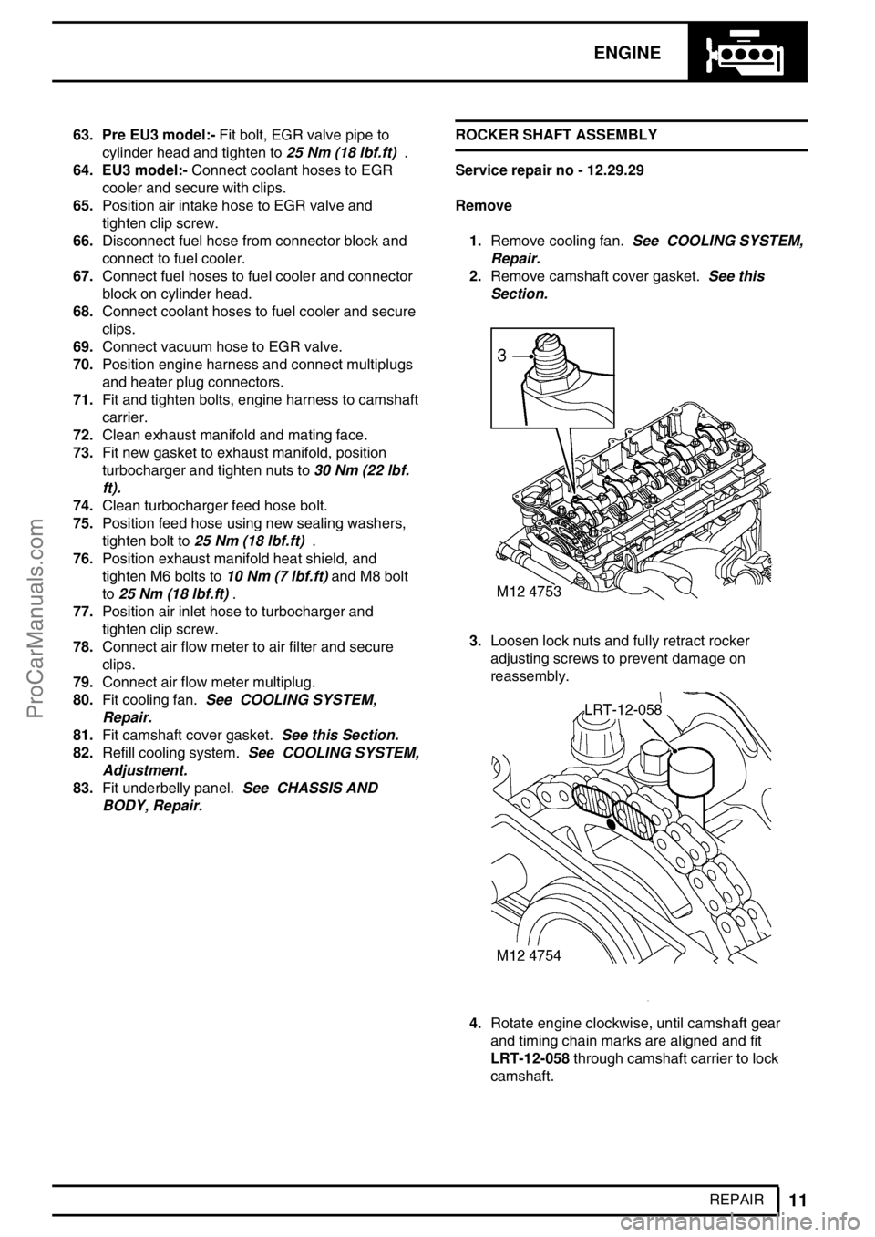
Service repair no - 12.29.29
Remove
1.Remove cooling fan.See COOLING SYSTEM,
Repair.
2.Remove camshaft cover gasket.See this
Section.
3.Loosen lock nuts and fully retract rocker
adjusting screws to prevent damage on
reassembly.
4.Rotate engine clockwise, until camshaft gear
and timing chain marks are aligned and fit
LRT-12-058through camshaft carrier to lock
camshaft.
ProCarManuals.com
Page 138 of 667

ENGINE
13
REPAIR 11.Before refitting the camshaft cover, the fuel
injector rockers must be adjusted.
12.RemoveLRT-12-058.
13.Rotate engine clockwise until No. 1 injector lobe
is at full lift.
14.Rotate rocker adjusting screw clockwise until the
injector plunger is felt to bottom out.
15.Rotate rocker adjusting screw anti-clockwise 1
complete turn to give the plunger the required
bump clearance and tighten rocker adjusting
screw locknut to16 Nm (12 lbf.ft).
CAUTION: Ensure screw does not turn as
locknut is tightened.
16.Carry out above procedure for the remaining 4
rockers.
17.After completion of rocker adjustment, slowly
rotate engine clockwise 2 complete turns by
hand to ensure that no injectors are bottoming
out on their plungers.
18.Fit camshaft cover gasket.See this Section.
19.Fit cooling fan.See COOLING SYSTEM,
Repair.GASKET - COVER - CAMSHAFT
Service repair no - 12.29.40
Remove
1.Remove battery cover.
2.Disconnect battery negative lead.
3.Remove 3 bolts and remove engine acoustic
cover.
4.Release clip and disconnect breather hose from
camshaft cover.
5.Remove 13 bolts, spacers and sealing washers
from camshaft cover.
6.Remove camshaft cover and gasket.
Refit
7.Clean camshaft cover and mating face.
8.Renew sealing washers and spacers as
necessary.
ProCarManuals.com
Page 165 of 667

12ENGINE
6
OVERHAUL 14.Clean fixed guide Allen screw and apply Loctite
242 to screw threads.
15.Fit fixed timing chain guide Allen screw and
tighten to25 Nm (18 lbf.ft).
16.Clean timing chain tensioner and fit new sealing
washer.
17.Fit timing chain tensioner and tighten to45 Nm
(33 lbf.ft).
18.Tighten camshaft sprocket bolts to36 Nm (27
lbf.ft).
19.Remove toolLRT-12-058from camshaft.
20.Lubricate a new’O’ring with engine oil and fit to
camshaft sprocket access plug.
21.Fit camshaft sprocket access plug.
22.Clean alternator/vacuum pump oil feed hose
union.
23.Lubricate a new’O’ring with engine oil and fit to
alternator/vacuum pump hose union.
24.Fit and tighten alternator/vacuum pump oil hose
union to10 Nm (7 lbf.ft).
25.Fit bolt securing alternator strap bracket to
cylinder head and tighten to25 Nm (18 lbf.ft).
26.Connect multiplugs to ECT sensor and EUIs.
CAUTION: Following cylinder head
overhaul, it will be necessary, before
fitting the camshaft cover, to adjust the
fuel injector rockers using the following
procedures:
27.Rotate engine clockwise until No. 1 EUI lobe is
at full lift.
28.Tighten No.1 rocker adjusting screw until the EUI
plunger is felt to’bottom out’.
29.Loosen rocker adjusting screw 1 complete turn
to give EUI plunger the required bump clearance
and tighten rocker adjusting screw locknut to16
Nm (12 lbf.ft).
CAUTION: Ensure screw does not turn as
locknut is tightened.30.Carry out above procedures for the remaining 4
rocker arms.
31.After completion of rocker adjustment, slowly
rotate engine clockwise 2 complete turns by
hand to ensure that no EUI’s are bottoming out
on their plungers.
32.Clean camshaft cover and mating face.
33.Fit new sealing washers and isolators as
necessary to camshaft cover.
34.Fit new camshaft cover gasket to cover.
CAUTION: Gasket must be fitted dry.
35.Fit camshaft cover to camshaft carrier, fit bolts
and working from the centre outwards, tighten
bolts to10 Nm (7 lbf.ft).
36.Fit inlet manifold gasket.See MANIFOLD AND
EXHAUST SYSTEM, Repair.
37.Fit exhaust manifold gasket.See MANIFOLD
AND EXHAUST SYSTEM, Repair.
38. EGR cooler fitted:-Position EGR pipe to cooler,
fit new Allen screws and tighten to10 Nm (7
lbf.ft).
ProCarManuals.com