Page 31 of 75

V6 Engine AJ-V6/AJ28
26
J.303.1316
J.303.1362
THROTTLE BODY ASSEMBLY
TP/APP SENSORS - GENERAL CHARACTERISTICStwo fixed external connectors. The TAC module is
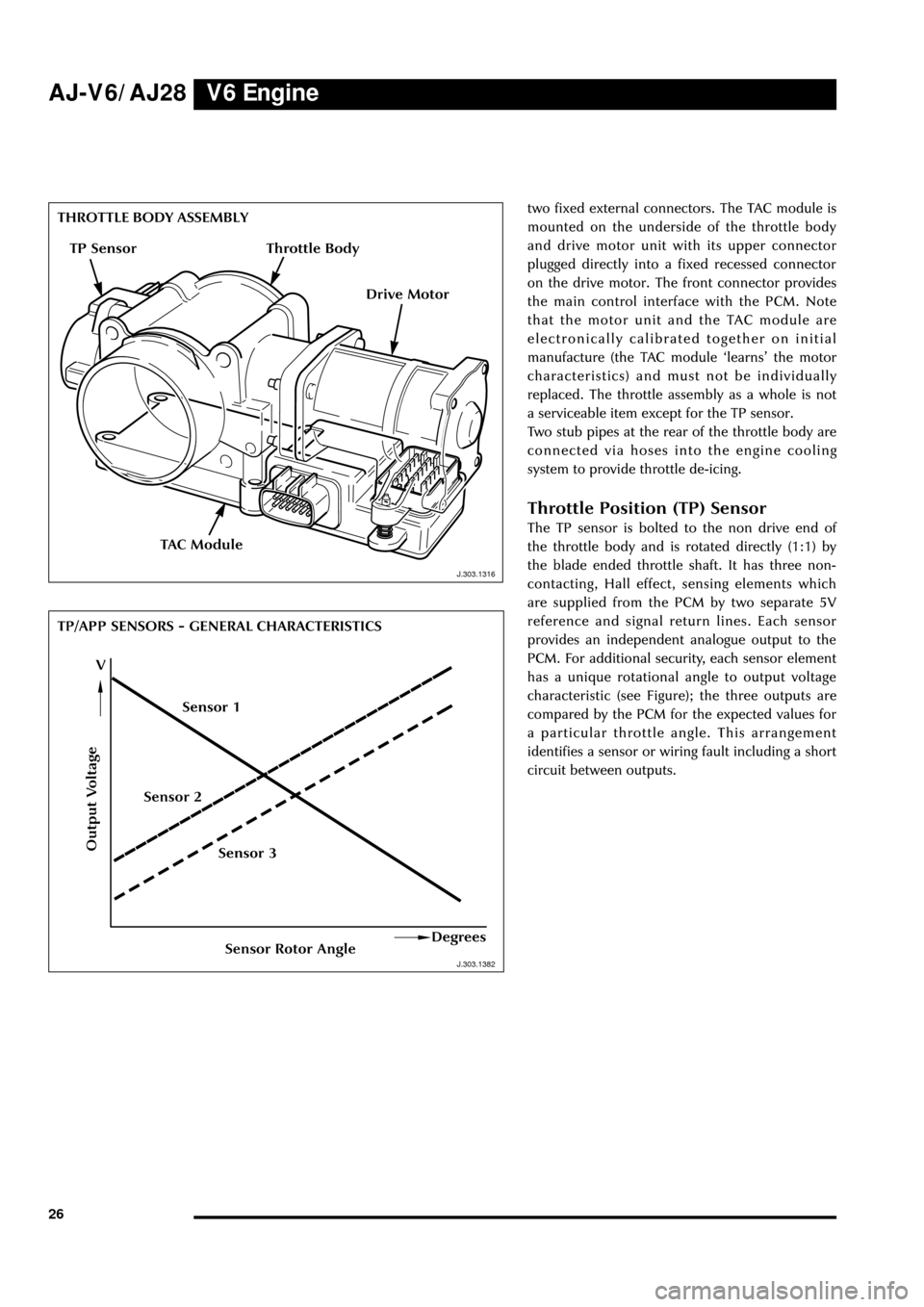
mounted on the underside of the throttle body
and drive motor unit with its upper connector
plugged directly into a fixed recessed connector
on the drive motor. The front connector provides
the main control interface with the PCM. Note
that the motor unit and the TAC module are
electronically calibrated together on initial
manufacture (the TAC module ÔlearnsÕ the motor
characteristics) and must not be individually
replaced. The throttle assembly as a whole is not
a serviceable item except for the TP sensor.
Two stub pipes at the rear of the throttle body are
connected via hoses into the engine cooling
system to provide throttle de-icing.
Throttle Position (TP) Sensor
The TP sensor is bolted to the non drive end of
the throttle body and is rotated directly (1:1) by
the blade ended throttle shaft. It has three non-
contacting, Hall effect, sensing elements which
are supplied from the PCM by two separate 5V
reference and signal return lines. Each sensor
provides an independent analogue output to the
PCM. For additional security, each sensor element
has a unique rotational angle to output voltage
characteristic (see Figure); the three outputs are
compared by the PCM for the expected values for
a particular throttle angle. This arrangement
identifies a sensor or wiring fault including a short
circuit between outputs.
Output Voltage
Sensor Rotor AngleDegrees
V
TAC Module
J.303.1382 J.303.1316
TP Sensor
Drive Motor
Sensor 3 Sensor 2Sensor 1
Throttle Body
Page 32 of 75

V6 EngineAJ-V6/AJ28
27
D.418.428
APP Sensor
303-050
APP SENSORAccelerator Pedal Position (APP)
Sensor
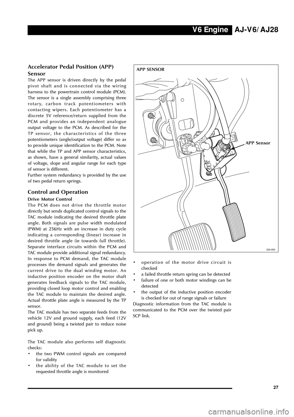
The APP sensor is driven directly by the pedal
pivot shaft and is connected via the wiring
harness to the powertrain control module (PCM).
The sensor is a single assembly comprising three
rotary, carbon track potentiometers with
contacting wipers. Each potentiometer has a
discrete 5V reference/return supplied from the
PCM and provides an independent analogue
output voltage to the PCM. As described for the
TP sensor, the characteristics of the three
potentiometers (angle/output voltage) differ so as
to provide unique identification to the PCM. Note
that while the TP and APP sensor characteristics,
as shown, have a general similarity, actual values
of voltage, slope and angular range for each type
of sensor is different.
Further system redundancy is provided by the use
of two pedal return springs.
Control and Operation
Drive Motor Control
The PCM does not drive the throttle motor
directly but sends duplicated control signals to the
TAC module indicating the desired throttle plate
angle. Both signals are pulse width modulated
(PWM) at 256Hz with an increase in duty cycle
indicating a corresponding (linear) increase in
desired throttle angle (ie towards full throttle).
Separate interface circuits within the PCM and
TAC module provide additional signal redundancy.
In response to PCM demand, the TAC module
processes the demand signals and generates the
current drive to the dual winding motor. An
inductive position encoder on the motor shaft
generates feedback signals to the TAC module,
providing closed loop motor control and enabling
the TAC module to maintain the desired angle.
Actual throttle plate angle is measured by the TP
sensor.
The TAC module has two separate feeds from the
vehicle 12V and ground supply, each feed (12V
and ground) being a twisted pair to reduce noise
pick up.
The TAC module also performs self diagnostic
checks:
¥ the two PWM control signals are compared
for validity
¥ the ability of the TAC module to set the
requested throttle angle is monitored¥ operation of the motor drive circuit is
checked
¥ a failed throttle return spring can be detected
¥ failure of one or both motor windings can be
detected
¥ the output of the inductive position encoder
is checked for out of range signals or failure
Diagnostic information from the TAC module is
communicated to the PCM over the twisted pair
SCP link.
Page 74 of 75

Powertrain ManagementAJ-V6/AJ28
69
Introduction
All powertrain and associated management
functions are controlled from a single unit, the
powertrain control module (PCM). These
functions are as follows:
¥ overall monitoring and control of
performance, fuel economy, emissions,
driveability and safety
¥ receives and processes direct inputs from
engine, transmission, fuel system and
ancillary systems sensors
¥ provides direct control of actuator devices
¥ communicates with other modules via the
SCP bus (eg to obtain wheel speed
information)
¥ provides system diagnostics to conform to
OBDII requirements.
Powertrain Control Module (PCM)
The basic PCM is common to the V6 and V8
engines but with unique programming to suit the
respective engine characteristics and some
differences in the interface circuits for the
different sensors and actuators.
The PCM is located below the LH or RH mounted
A/C evaporator/blower unit and has a single
connector panel which protrudes through the
forward bulkhead into the engine bay.
The PCM has three connectors:
¥ a 60 pin connector which provides the
interfacing with the engine wiring harness:
carries engine mounted sensor inputs and
output control signals
¥ a 32 pin connector which carries the
transmission sensing and control signals and
also the rear HO2 sensor inputs
¥ a 58 pin connector which carries non engine
mounted sensor and actuator signals and
provides the PCM link to the SCP bus.
Powertrain Sub-Systems
Brief descriptions of PCM control of new
subsystems are given in the relevant engine and
transmission sections (electronic throttle,
returnless fuel etc).
J.303.1393
POWERTRAIN CONTROL MODULE
J.303.1393