1999 HONDA CR-V Upper control
[x] Cancel search: Upper controlPage 123 of 1395

Timing Belt
Removal
Replace the timing belt at 105,000 miles (168,000 km)
according to the maintenance schedule {normal condi-
tions/severe conditions). lf the vehicle is regularly driven
in either of the following conditions, replace the timing
belt at 60,000 miles (U.S.A.l 100.000 km (Canada).
- ln very high temperatures (over 110'F, 43"C).- In very low temperatures (under -20"F. -29"C).
Turn the crankshaft pu\ley so the No. 1 piston is at
top dead center (TDC).
Remove the guard bar and splash shield (see page
5-7 ).
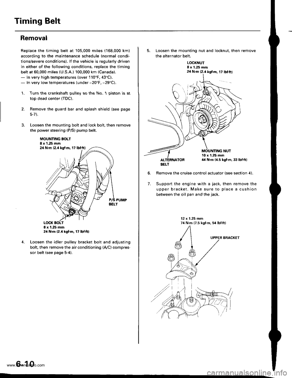
Loosen the mounting bolt and lock bolt. then remove
the power steering (P/S) pump belt.
MOUNNNG BOLT8 x 1.25 rnm
1.
2.
,l
4. Loosen the idler pulley bracket bolt and adjusting
bolt, then remove the air conditioning (lVC) compres
sor belt (see page 5-4).
6-10
24 N.m {2.4 kgt.m, 17 lbf.ftl
24 N.m 12.4 kgf.m, lt lbf.ftl
5. Loosen the mounting nut and locknut, then remove
the altefnator belt.
LOCKNUTI x 1.25 mm2a N.m 12.4 kgt m, 17 lblftl
6.
10 x 1,25 mm4,1 N.m (,1.5 kgt m, 33 lbtftl
Remove the cruise control actuator (see section 4).
Support the engine with a jack, then remove the
upper bracket. Make sure to place a cushion
between the oil Dan and the iack.
12 x 1.25 mm74 N.m (7.5 kgf m, 54 lbtftl
7.
BRACKET
AELT
www.emanualpro.com
Page 132 of 1395

13. Remove the upper radiator hose, heater hose and
water bypass hose.
WATER BYPASS
UPPEBRADIATORHOSE
17
HEATERHOSE
Remove the engine wire harness connectors and
wire harness clamps from the cylinder head and the
intake manifold.
o Four fuel injector connectors
. Engine coolant temperature (ECT) sensor con-
neclor
. Radiator fan switch connector
. Coolant temperature gauge sendlng unlt connec-
tor
. Throttle position sensor connector
. Manifold absolute pressure {MAP) sensor con-
nector
Primary heated oxygen sensor (primary HO2S)
connector
ldle air control (lAC) valve connector
Distributor connector
Remove the spark plug caps and distributor from the
cylinder head.
Remove the cruise control actuator (see section 4).
Support the engine with a jack, then remove the
upper bracket. Make sure to place a cushion
between the oil pan and the iack (see page 6-10).
a
18. Remove the cylinder head cover.
19. Inspect the timing belt (see page 6-9).
CYLINDER
(cont'd)
6-19
www.emanualpro.com
Page 666 of 1395

Interlock System
Park Pin Switch Replacement -'97 - 98 Models
SRS components are located in this area. Review the SRS component locations, precautions, and procedures in the SRS
section (24) before performing repairs or service.
1. Remove the instrument Danel lower cover (see section 20).
2. Remove the upper and lower steering column covers (see section li,.
3. Remove the flange nuts and bolts securing the steering column. then lower the steering column.4. Disconnect the shift lock solenoid and the park pin switch connectors.
5. Remove the harness clamp bracket.
6. Remove the bolts secu ring the shift lever assembly, then removetheshift lever assembly.
7. Remove the screws securing the shift lock solenoid. then remove the shift lock solenoid,
8. Remove the parkpin switch connector from the shift lever control bracket.
9. Remove the control checker from the shift lever control bracket.
10. Remove the park Din switch from the control checker.
PARK PIN SWITCH
PARK PINSWITCH CONNECTOR
scnEw2.5 N m 10.25 kgt.m, 1.8 lbtftl
9.3 N.m 10.95 kgf.m, 6.9 lbl.ft)
BRACKETCONTROL CHECKER
11. Install the new Dark Din switch on the control checker.
12. lnstall the control checker on the shift lever control bracket.
13. Routethe park pin switch harness through thecutoutofthe shift lever control bracket, then install the park pin switchconnector on the bracket.
14. Install the sh ift lock solenoid by a ligning the joint of the sh ift lock solenoid plu nger with the tip of the shift lock exten-sion.
15. Secure the shift lock solenoid with the screws.
15. Install the shift lever assembly in the reverse order of the removal.'17. Check the operation of the shift lever and the shift lock.
14-150
www.emanualpro.com
Page 667 of 1395

Park Pin Switch - Over-Drive (O/Dl Switch Replacement -'99 - 00 Models
SRS components are located in this area. Review the SRS component locations, precautions, and procedures in the SRS
section {24) before performing repairs or service.
NOTE: lf replacement of the park pin switch or the O/D switch is required. replace them as a set.
1. Remove the instrument panel lowercover(see section 20).
2. Remove the upper and lower steering column covers (see section 17).
3. Remove the flange nuts securing the steering column. then lower the steering column.
4. Disconnect the shift lock solenoid and the park pin switch - O/D switch connectors
5. Remove the harness clamp bracket.
6. Remove the bolts securing the shift lever assembly, then remove the shift lever assembly.
7. Remove the screws securing the shift lock solenoid, then remove the shift lock solenoid.
8. Cut the O/D switch wires (REDand BLK),then remove the con nector from the shift lever control bracket
9. Remove the control checker from theshift lever control bracket
10. Remove the oark oin switch from the control checker.
11. Remove the shift lever knob from the shift lever, then remove the O/D switch from the shift lever knob.
SCREW2.5 N.m 10.25 kgtm, 1.8lbf,ft)SHIFT LEVER CONTROLBRACKET
PARK PIN SWITCH -
o/D swlTcHCONNECTOR
2.5 N.m (0.25 kgt m,1.8 tbf.fr)
HABNESS CLAMP BRACKET
9.3 N.m 10.95 kgl.m.6.9 tbf ft)
SHIFT LEVER KNOB6-12N,m{0.6 - 1.2 kgt.m.4 - 8.7 lbf ftl
SHIFT LEVERo/o swlTcH
12. Route the new O/D switch wires through the shift lever knob, shift lever, and shift lever control bracket, then install
the knob on the shift lever, and install the switch in the knob.
13. Install the new park pin switch on the control checker, then install the control checker on the shift lever control brack-
et.
14. Routethe parkpin switch harnessthroughthecutoutoftheshift lever control bracket.
15. Install the O/D switch wire terminals in the connector cavities securely. The wire terminals can be installed in cavity
No. 1 or No.2.
16, Install the connector and the harness clamp on the bracket.
17. tnstall the shift lock solenoid by aligning the joint ot the shift lock solenoid plu nger with the tip of the shift lock exten-
sion, then secure the shift lock solenoid with the screws,
18. lnstall the shift lever assemblv inthe reverse order of removal.
19. Adjust the clearance between the O/D switch wires and the edge of the sh ift lever control bracket (see page 14-270).
20. Check the shift lever operation and shift lock operation.
14-151
www.emanualpro.com
Page 1034 of 1395

Dashboard Removal and Installation
SRS components are located in this area. Review the SRS
component locations, precautions, and procedures in the
SRS section {24) before preforming repairs or service.
CAUTION:
. When prying with a flat-tip screwdriver, wrap h withprotective tap€, and apply protective tape around the
related parts to prevgnt damage.
. Put on gloves to prot€ct your hands.
NOTE:
. An assistant is helpful when removing and installing
the dashboard.
. Take care not to scratch the dashboard, bodv and
other related parts.
1.Make sure you have the anti-theft code for the
radio, then write down the frequencies for the
radio's preset buttons.
Disconnect the negative battery cable. and wait at
least three minutes before beginning work.
Removei
a Driver's dashboard lower cover and knee bolster(see page 20-48)
. Glove box (see page 20-49)
. Lower console cover and center pocket (A/T
model, see page 20-49)
. Center console and center upper pocket (M/T
model, see page 20-47)
. Center dashboard lower cover (see page 20-50)
. Power window switch (see page 20-51)
. Driver's side air vent (see page 20-52)
. Driver's side defogger trim (see page 20-52)
Disconnect the driver's airbag connector, and lower
the steering column (see section 17)
NOTE: To prevent damage to the steering column,
wrap it with a shop towel.
2.
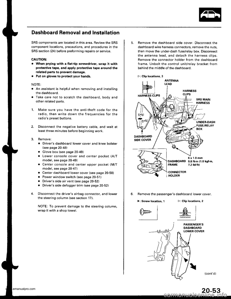
5. Remove the dashboard side cover. Disconnect the
dashboard wire harness connectors, remove the nuts,
then move the under-dash fuse/relay box. Disconnect
the antenna lead, and detach the harness clips.
Remove the connector holder from the dashboard
frame. Unbolt the control unit/relay bracket from
behind the middle of the dashboard.
HARNESS
6. Remove the passenger's dashboard lower cover.
D: Clip locations,
nl
-$t- Issj
I
ANTENNALEAD
>: Clip locations.
rttl
slllll
>: Scr€w location, 1
I
SF:oo I-l
SRS MAINHARNESS
UNDER.DASHFUSE/RELAYBOX
OASHBOARDSIDE COVER
6x1.0mm9.8Nm11.0kgf.m,7.2tbt.ftlDASHBOARDFFAME
CONNECTORHOLDER
PASSENGER'SDASHBOARDLOWER COVER
{cont'd)
www.emanualpro.com
Page 1049 of 1395

Seats
Rear Seat Linkage Disassembly and Reassembly (cont'd)
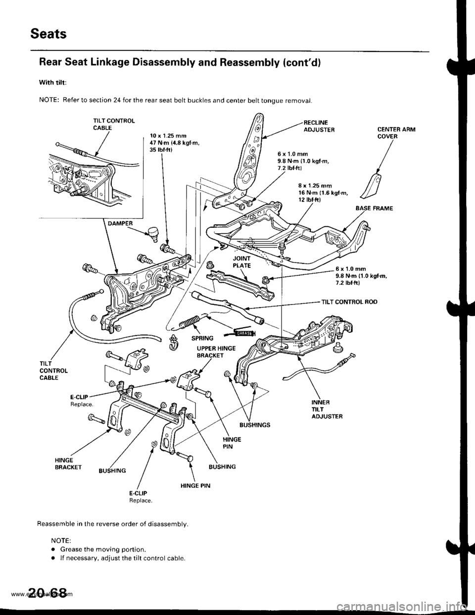
with tilt:
NOTE: Refer to section 24 for the rear seat belt buckles and center belt tongue removal
TILT CONTFOLCABLE10 x 1.25 mm47 N.m {i1.8 kgt.m,35 tbf.ft)
ARM
6x1.0mm9.8 N.m n.0 kgt.m,7.2 tbt.tll
CENTEBCOVER
/
n
//-)
ASE FRAME
8 r 1.25 mm16 N.m (1.6 kgf.m,12 tbt.ftl
DAMPER
6x1.0mm9.8 N.m 11.0 kgtm,7.2 tbttr)
TILT CONTROL ROD
A
@
SPRING
UPPER HINGE
TILTCONTROLCABLE
Replace.
q
BUSHING
E.CLIPReptace.
Reassemble in the reverse order of disassembly.
NOTE:
. Grease the moving ponion.
. lf necessary, adjust the tilt control cable.
20-64
HINGE PIN
www.emanualpro.com
Page 1184 of 1395

Connector ldentification and Wire Harness Routing
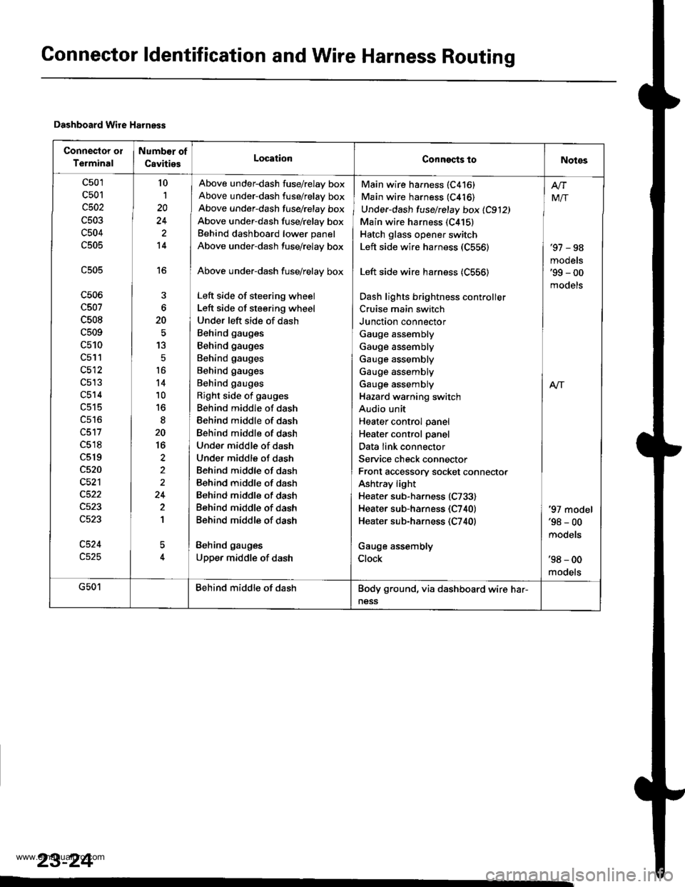
Dashboard Wire Harness
Connector ol
Terminal
Numb€r of
CavitiesLocationConngcts toNotes
c501
c501
c502
c503
c504
c505
c506
c507
c508
c509
c510
c511
c512
c514
c518
c519
c520
c521
c524
10
1
20
14
16
6
20
13
5
t6
14
10
to
20
16
2
24
2
1
5
Above under-dash fuse/relay box
Above under-dash fuse/relay box
Above under-dash fusehelay box
Above under-dash fuse/relay box
Behind dashboard lower panel
Above under-dash fuse/relay box
Above under-dash fuse/relay box
Left side of steering wheel
Left side of steering wheel
Under left side of dash
Behind gauges
Behind gauges
Behind gauges
Behind gauges
Behind gauges
Right side of gauges
Behind middle of dash
Behind middle of dash
Behind middle of dash
Under middle of dash
Under middle of dash
Behind middle of dash
Behind middle of dash
Behind middle of dash
Behind middle of dash
Behind middle of dash
Behind gauges
Upper middle of dash
Main wire harness (C416)
Main wire harness (C416)
Under-dash fuse/relay box 1C912)
Main wire harness (C415)
Hatch glass opener switch
Left side wire harness (C556)
Left side wire harness (C556)
Dash lights brightness cont.oller
Cruise main switch
Junction connector
Gauge assembly
Gauge assembly
Gauge assembly
Gauge assembly
Gauge assembly
Hazard warning switch
Audio unit
Heater control panel
Heater control panel
Data link connector
Service check connector
Front accessory socket connector
Ashtray light
Heater sub-harness (C733)
Heater sub-harness {C740}
Heater sub-harness (C740)
Gauge assembly
Clock
'97 - 98
models'99 - 00
models
Mir
A/r
'97 model'98 - 00
mooets
'98 - 00
models
G501Behind middle of dashBody ground, via dashboard wire har-
ness
23-24
www.emanualpro.com