Page 5 of 1395
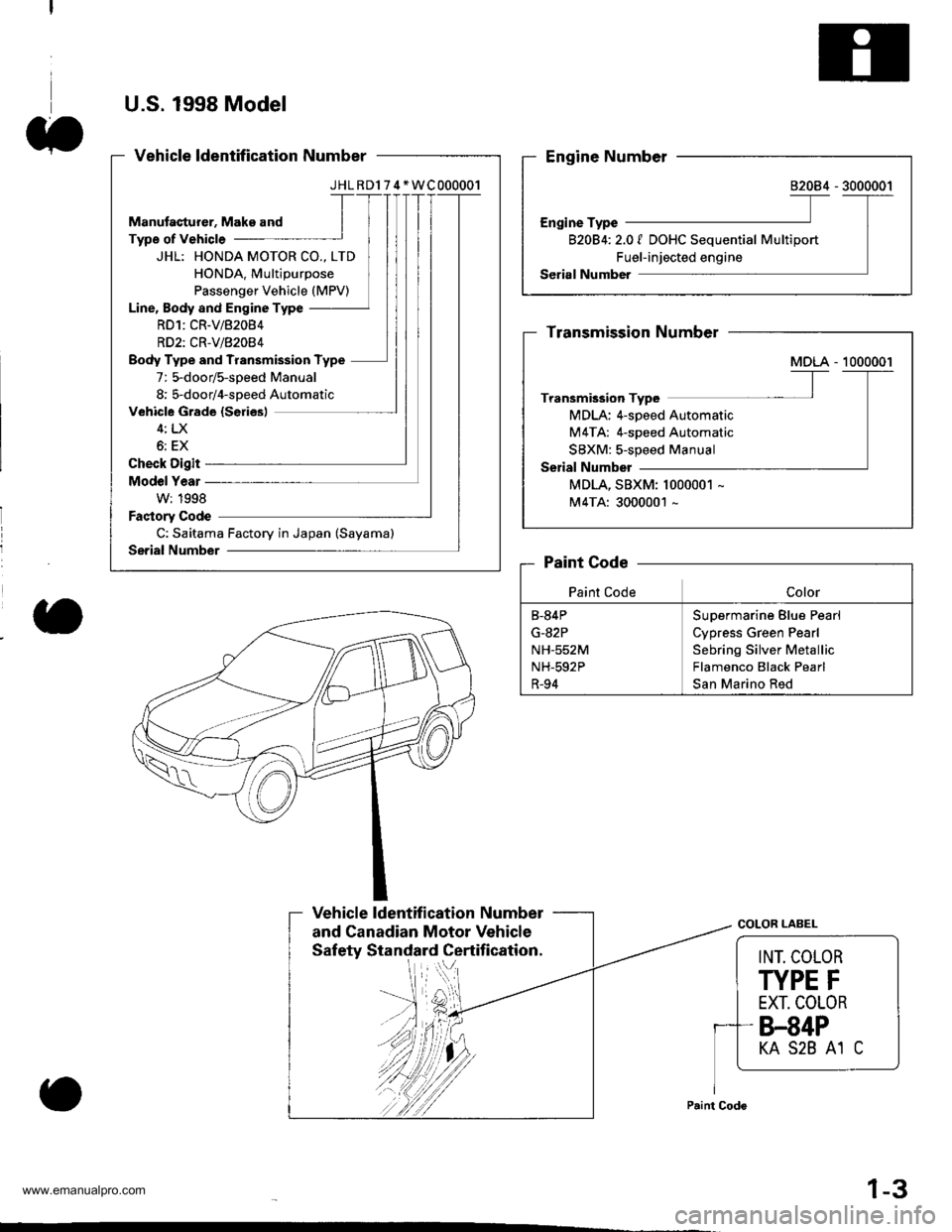
U.S. 1998 Model
JHLRD174*WC000001
JHL: HONDA MOTOR CO., LTD
HONDA. Multipurpose
Passenger Vehicle (MPV)
Line, Body and Engine Type
RD1:CR-V/82084
RD2: CR'V/82084
Body Type and Transmission Type
7: 5-door/s-soeed Manual
8; 5-door/4-soeed Automatic
C: Saitama Factory in Japan (Sayama)
B20B4t 2.01 DOHC Sequential Multiport
Fuel-injected engine
MDLA: 4-speed Automatic
M4TA: 4-speed Automatic
SBXM:s-speed Manual
MDLA, SBXM: 1000001 -
M4TA: 3000001 -
B-84P
G-82P
NH-552M
NH-592P
R-94
Supermarine Blue Pearl
Cypress Green Pearl
Sebring Silver Metallic
Flamenco Black Pearl
San Marino Red
Vehicle ldentification Number
and Canadian Motor VehicleCOLOR LABEL
INT. COLOR
TYPE F
EXT. COLOR
8.84P
KA S2B A1 C
1-3
www.emanualpro.com
Page 7 of 1395
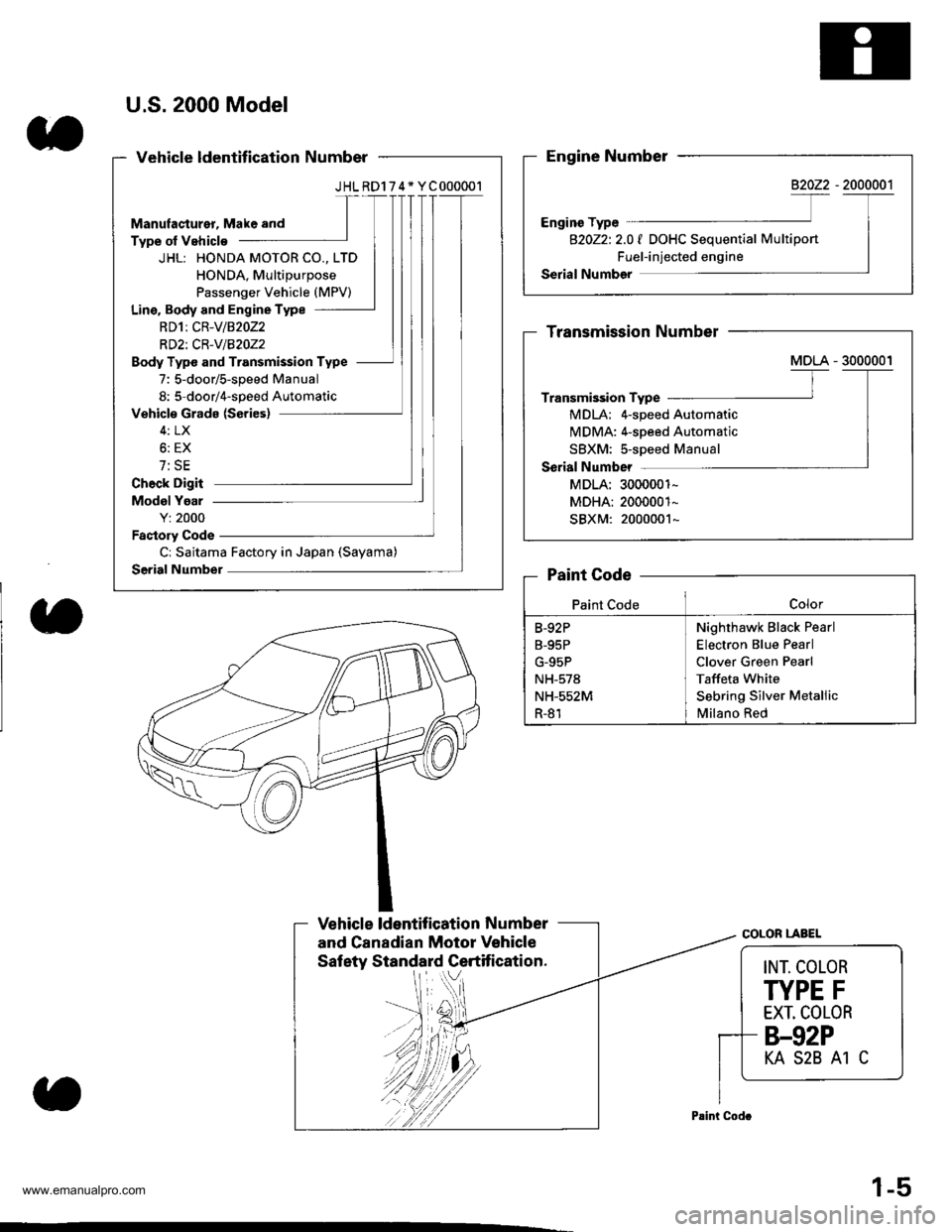
U.S.2000 Model
JHLRD174* YC000001
JHL: HONDA MOTOR CO., LTD
HONDA, Multipurpose
Passenger Vehicle (MPV)
Line. Body and Engine Type
RDlt CR-V/82022
RD2i CR-v/BzOz2
Body Type and Transmission Type
7: 5-door/s-speed Manual
8: 5 door/4-soeed Automatic
Cr Saitama Factory in Japan (Sayama)
B20Z2t 2.0 I DOHC Seouential MultiDort
Fuel-injected engine
MDLA; 4-speed Automatic
MDMA: 4-speed Automatic
SBXM: s-speed Manual
MDLA: 3000001-
MDHA: 2000001-
SBXM: 2000001-
Nighthawk Black Pearl
Electron Blue Pearl
Clover Green Pearl
Taffeta White
Sebring Silver Metallic
Milano Red
B-92P
B-95P
G-95P
NH-578
NH-552M
R-81
Saf ety Standard Certif ication.lrl ..V
COLOR LABEL
INT. COLOR
TYPE F
EXT, COLOR
8.92P
KA S2B A1 C
1-5
www.emanualpro.com
Page 9 of 1395
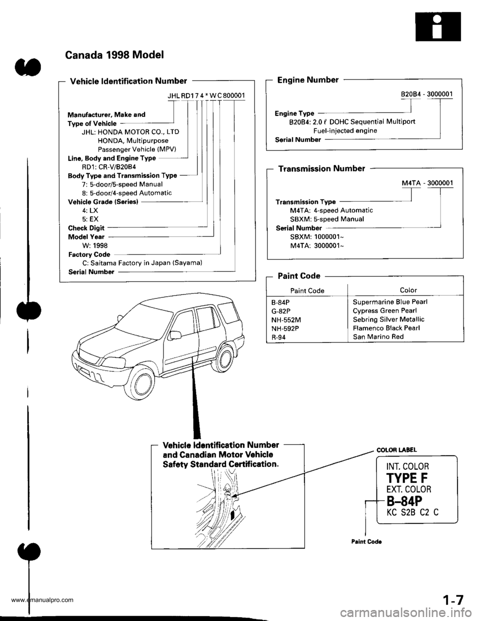
Canada 1998 Model
JHL RD1 7 4*WC800001
JHL: HONDA MOTOR CO., LTD
HONDA, Multipurpose
Passenger Vehicle (MPV)
Lino, Body and Engine Type
RD1: CR-V/82084
Body Type and Transmission Type
7: 5-door/s-speed Manual
8: 5-door/4-speed Automatic
C: Saitama Factory in Japan (Sayama)
82084:2.0 | DOHC Sequential Multiport
Fuel-injected engine
M4TA: 4-speed Automatic
SBXM: 5-speed Manual
SBXM:1000001-
M4TA: 3000001*
Supermarine BIue Pearl
Cypress Green Pearl
Sebring Silver Metallic
Flamenco Black Pearl
San Marino Red
B-84P
G-82P
NH-552M
NH-592P
R-94
COLOR LABEL
INT. COLOR
TYPE F
EXT. COLOR
8.84P
KC S2B C2 C
1-7
www.emanualpro.com
Page 138 of 1395
Valve Guides
Valve Movement
1. Measure the guide-to-stem clearance with a dial
indicator while rocking the stem in the direction of
normal thrust (wobble method),
lntake Valve Stem-to-Guide Clearance:
Standard (Newl: 0.04 - 0.10 mm
(0.002 - 0.004 in)
Service Limit 0.16 mm (0.006 in)
Exhaust Valve Stem-to-Guide Clearance:
Standard {Newl: 0.10 - 0.16 mm
(0.004 - 0.006 inl
Service Limit: 0,22 mm (0.009 inl
lf the measurement exceeds the service limit,
recheck using a new valve.
lf the measurement is now within the service limit,
reassemble using a new valve.
lf the measurement still exceeds the limit, subtract the
O.D. of the valve stem, measured with a micrometer,
from the l.D. of the valve guide, measured with an
inside micrometer or ball gauge.
Take the measurements in three places along the
valve stem and three places inside the valve guide
The difference between the largest guide measure-
ment and the smallest stem measurement should
not exceed the service limit.
lntake Valve Stem-to-Guide Clearance:
Standard (New): 0.02 - 0.05 mm
{0.001 - 0.002 in)
Service Limit: 0.08 mm (0.003 in)
Exhaust Valve Stem-to-Guide Clearance:
Standard (New): 0.05 - 0.08 mm
(0.002 - 0.003 in)
Service Limit: 0.11 mm (0.004 in)
2.
3.
Replacement
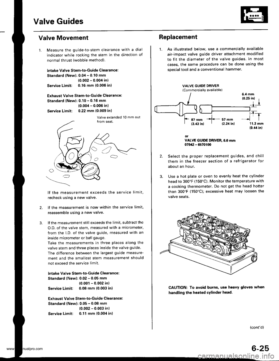
1. As illustrated below, use a commercially available
air-impact valve guide driver attachment modified
to fit the diameter of the valve guides. In most
cases, the same procedure can be done using the
sDecial tool and a conventional hammer.
VALVE GUIDE DRIVER(Commerciallv available)
2.
3.
(0.25 inl I
_,1-r
,_T-_lrl
'11.3 mm(0.{,r in}
orVALVE GUIDE DRIVER, 6.6 mm0t9a:I - G5t01q)
Select the proper replacement guides. and chill
them in the freezer section of a refrigerator for
about an hour.
Use a hot plate or oven to evenly heat the cylinder
head to 300"F (150"C). Monitor the temperature with
a cooking thermometer. Do not get the head hofter
than 300'F (150"C); excessive heat may loosen the
valve seaIs.
6.4 mm
CAUTION: To avoid burns, uss heavy gloves when
handling the heated cylinder head.
(cont'd)
6-25
*]-- sz mm' l2.21inl
www.emanualpro.com
Page 148 of 1395
Special Toolstl
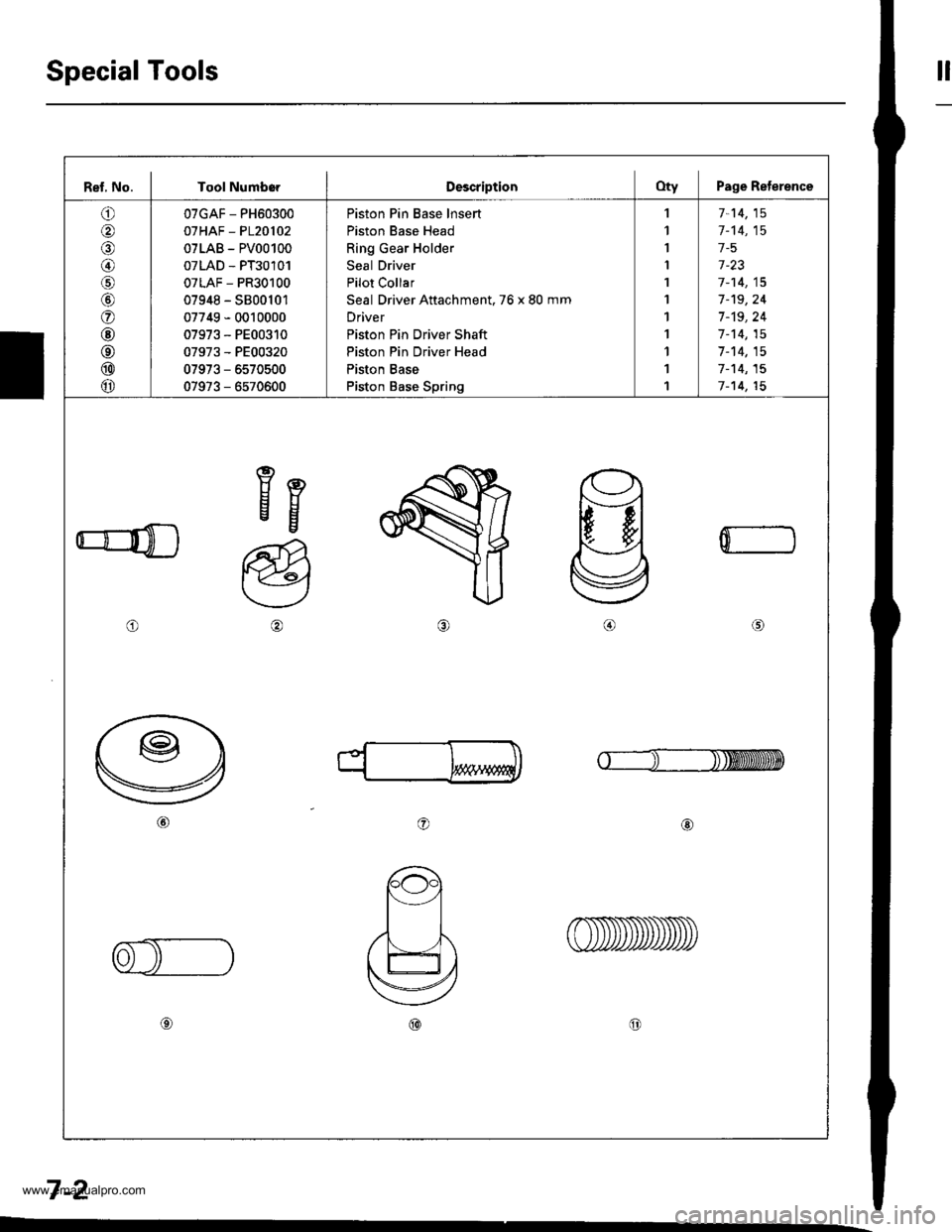
Ref, No. I Tool NumborDescriptionOty Page Reterence
o
@
@/6
@
o
@
@
@
@
07GAF - PH60300
07HAF - P120102
07LAB - PV00100
07LAD - PT30101
07LAF - PR30100
07948 - S800101
07749 - 0010000
07973 - PE00310
07973 - PE00320
07973 - 6570500
07973 - 6570600
Piston Pin Base lnsert
Piston Base Head
Ring Gear Holder
Seal Driver
Pilot Collar
Seal Driver Attachment. 76 x 80 mm
Driver
Piston Pin Driver Shaft
Piston Pin Driver Head
Piston Base
Piston Base Spring
,l
1
I
I
1
1
1
1
1
1
1
7-14,15
1-'t4,15
1-5
1-23
7-14,15
7-'t9,24
7 -'t9, 24
1-14,15
7-14,15
7-'t4,15
7-14,15
eEEg
o
a@
0
o@
7-2
www.emanualpro.com
Page 160 of 1395
Piston PinsConnecting Rods
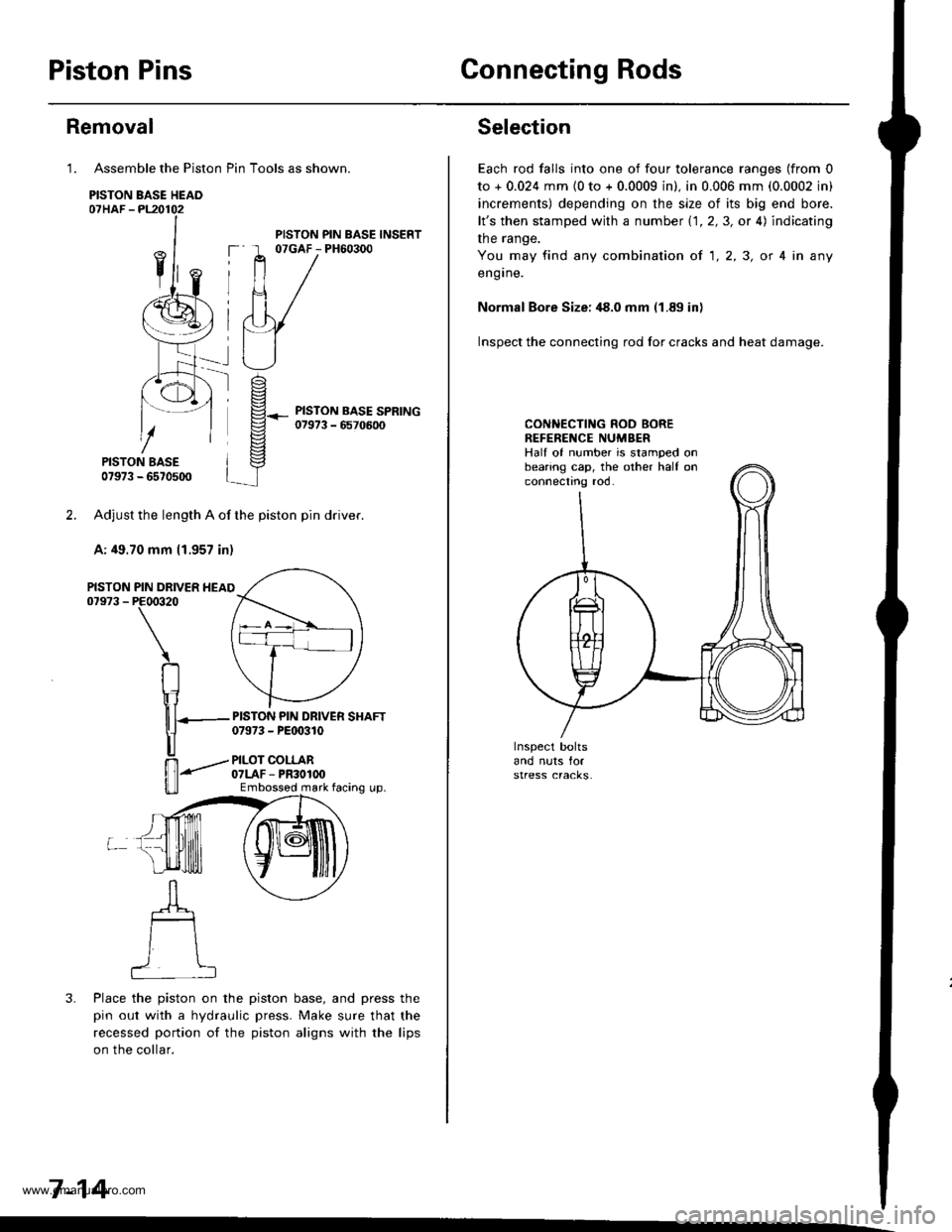
Assemble the Piston Pin Tools as shown.
PISTON BASE HEAO07HAF -PL20102
PISTON BASE07973 - 6570500
Adjust the length A of the piston pin dflver.
A: 49.70 mm 11.957 in)
PIN DRIVER HEAIPE00320
\
RIr1
nT---
u
ffi-"""-
u_ll
3. Place the piston on the piston base, and press the
pin out with a hydraulic press. Make sure that the
recessed portion of the piston aligns with the lips
on the collar.
7-14
Removal
1.
PISTON07973 -
PISTON PIN BASE INSERT07GAF - PH60300
PISTON PIN DRIVER SHAFT07973 - PEt 0310
PILOT COLLAR07LAF - PR30100Embossod mark facing up.
Selection
Each rod falls into one of four tolerance ranges (from 0
to + 0.024 mm {0 to + 0.0009 in). in 0.006 mm (0.0002 in)
increments) depending on the size of its big end bore.
lt's then stamped with a number 1.1.2,3, or 4) indicating
the range.
You may find any combination ot 1,2,3, or 4 in any
engrne.
Normal Bore Size: ,18.0 mm (1.89 in)
Inspect the connecting rod for cracks and heat damage.
CONNECTING ROD BOREREFENENCE NUMBERHalf of number is stamped onbearing cap, the other half onconnectno roo.
www.emanualpro.com
Page 279 of 1395
DTC(MlL indicationlDotection ltomProbable CausePage
P0500 t17)*,
Vehicle SpeedSensor CircuitMalfunction
Vehicle Speed SensorVehicle Speed Sensor circu itECtVI1 1-135
P0501 l17J*1
Vehicle SpeedSensor CircuitMalfunction
Vehicle Speed SensorVehicle Speed Sensor circuitPCM11-135
P0505 (14)ldle ControlSystemMalfunction
IAC valveThrottle BodyFast idle thermo valve*11 ']- 150
P0700P0715PO720P0730P0740P0753P0758
AutomaticTransaxle
Section l4
P1106 (13)BarometricPressure CircuitRange/Performance Problem
ECM/PCM (Baro sensor)
11-137
P1107 (13)BarometricPressure CircuitLow InPut
. ECM/PCM {Baro sensor)11-137
P1108 (13)BarometricPressure CircuitHigh Inpur
ECM/PCM {Baro sensor)11,137
P1121 (7)Throttle PositionLower ThanExpected
. TP sensor11-109
P1122 (7)Throttle PositionHigher ThanExpected
' TP sensor1 1-'109
P112a (5)Manifold AbsolutePressure Lower ThanExpected
. MAP sensor11-94
P1129 (5)Manifold AbsolutePressure HiqherThanExpected
' MAP sensor1l-94
P1297 (20)Electrical LoadDetector CircuitLow Input
Electrical Load DetectorElectrical Load Detector circuitECM/PCM1 1- 138
P1298 (20)Electrical LoadDetector CircuitHigh Input
Electrical Load DetectorElectrical Load Detector circuitECM/PCM11-140
P1300'3
P0301P0302P0303P0304
7l721314
Random lvlisfirelgnition systemFuel supply systemMAP sensorIAC valveContaminated fuelLack offuel
11-126
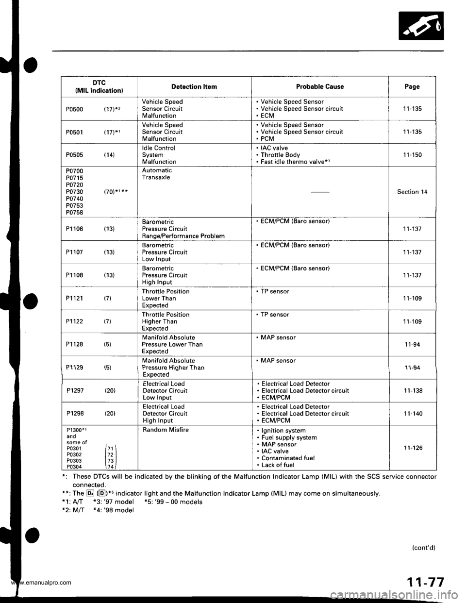
*: These DTCS will be indicated by the blinking of the Malfunction Indicator Lamp {MlL} with the SCS service connector
connected.**:The E (E])+s indicator light and the Malfunction Indicator Lamp (MlL) may come on simultaneously.*1:A,./T "3: '97 model +5: '99 - 00 models*2: M/T *4:'98 model
{cont'd)
11-77
www.emanualpro.com
Page 292 of 1395

PGM-FI System
Manifold Absolute Pressure (MAPI Sensor
The scan tool indicates Diagnostic Trouble Code (DTC) POl07: A low input (high vacuum) problem in theManifold Absolute Pressure (MAP) sensor,
The MAP sensor convens manifold absolute pressure into electrical signals and inputs the ECM/pCM.
OUTPUIVOLTAGE
tvl3.s
3.0
2.5
2.O
1.5
1.0
0.5
o .5 ro- 15^ 1olin.H9) GAUGEREADIT{G
lmmHgl
3025
100 200 300 a00 5oo 6fi, 7d)
MAP SENSOR 3P CONNECTOR IC131I
vccl(YEL/RED}
Th6 MIL has b€en reoorted on.DTC P0107 is 3tored.
Problom verification:1. Turn the ignition switch ON lll).2. Check the lvlAP with the scanroot.
lrtormittem tailu.e, lystam b OKat thb timo. Check tor poor con-noctions or loosa wird at C131(MAP rensor) and rt the ECM/PCM.
ls approx. 101 kPa (760 mmHg,30 in.Hg),2.9 V indicated?
Check for an op6n in wi.o IVCC1linel:1. Turn the ignition switch OFF.2. Disconnect the MAP sensorconnector,3. Turn the ignition switch ON {ll}.4. Measure voltage between theMAP sensor connector No. 1termanal and No. 2 terminal.
Roprir op€n in the wir6 bstweentho ECM/PCM (D4, C19*l and theMAP sensor.
ls there approx. 5 V?
(To page 11-91)
11-90
Wiro side ol temale terminals
www.emanualpro.com