Page 440 of 1395
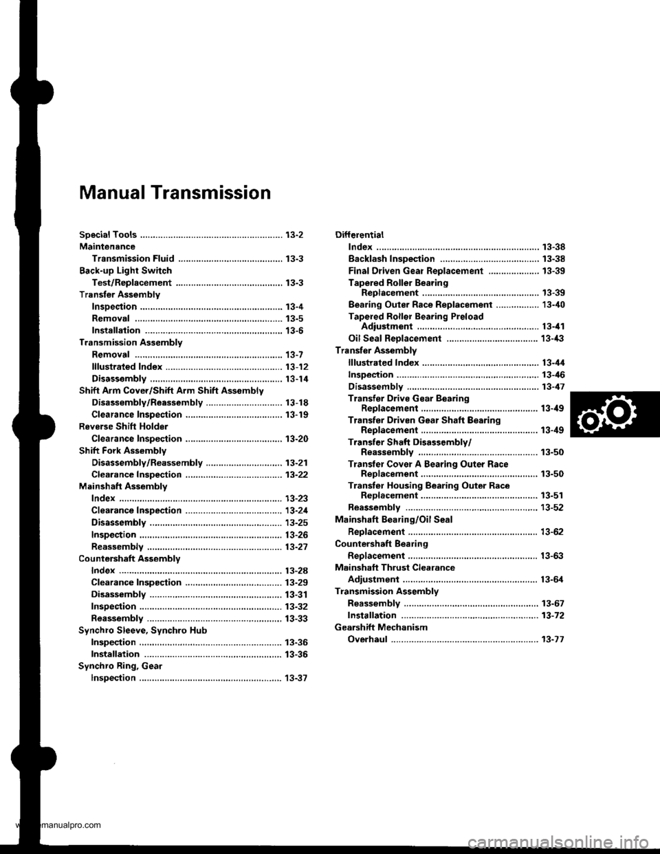
Manual Transmission
Diff€rential
lndex ...................... ......... 13-38
Backlash Inspestion ..,....,.,.....................,......, 13-38
Final Driven Gear Replacement .................... 13-39
Tapered Roller BearingReplacement ............. 13-39
Bearing Outer Race Replacement ......,.,........ 13-i10
Tapered Roller Bearing PreloadAdiustment ............... 13-il1
Oil Seal Reolacement .................................... 13-/l:}
Transfer Assembly
lllustrated Index ............. 13-il4
Inspection ..,....,.,......,...... 13-46
Disassembly ................... 13-47
Transfer Drive Gear BearingReplacement ...,..................,....................... 13-ilg
Transfer Driven Gear Shaft BearingReplacement .............................................. 13-ilg
Transfer Shaft Disassembly/Reassembly .............. 13-50
Transler Cover A Bearing Outer RaceRep1acement.........,.,.,..........,....,...,.........,., 13-50
Transter Housing Bearing Outer RaceReD1acement.............................................. 13-51
Reassembly ..-............,... 13-52
Mainshaft Bearing/Oil Seal
Beplacement .................. 13-62
Countershaft Bearing
Replacement .,,.,.,., ..,...... 13-63
Mainshaft Thrust Clearance
Adiustment .................... 13-6,1
Transmission Assembly
Reassembly .,.,.,.,..,.,....,., 13-67
fnstaffation .,.,.............,... 13-72
Gearshift Mechanism
Overhaul ................ .........13-17
www.emanualpro.com
Page 441 of 1395
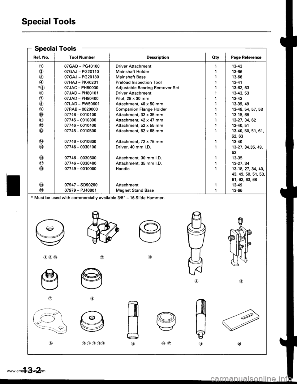
Special Tools
ll
Ref. No. I Tool NumberDsscriptionOty I Page Roterence
o
o,6)
@-o
\9'
a
@6r
@
o
@
@
@
@
@
@
@
@
@
07GAD - PG40100
07GAJ - PG20110
07GAJ - PG20130
07HAJ - PK40201
07JAC - PH80000
07JAD - PH80101
07JAD - PH80400
07LAD - PW50601
07RAB - 0020000
07746 - 0010100
07746 - 0010300
07746 - 0010400
07746 - 0010500
07746 - 0010600
07746 - 0030100
07746 - 0030300
07746 - 0030400
07749 - 0010000
07947 - SD90200
07979 - PJ40001
Driver Attachment
Mainshaft Holder
Mainshaft Base
Preload Inspection Tool
Adjustable Bearing Remover Set
Driver Attachment
Pilot, 28 x 30 mm
Attachment, 40 x 50 mm
Companion Flange Holder
Attachment,32 x 35 mm
Attachment, 42 x 47 mm
Attachment, 52 x 55 mm
Attachment, 62 x 68 mm
Attachment, 72 x 75 mm
Driver, 40 mm l.D.
Attachment. 30 mm l.D.
Attachment, 35 mm l.D.
Handle
Attachment
Magnet Stand Base
1
1
1'l
1
1
1
1
1
1'I
1
1
1
1
13-43
13-66
13-66
13-41
13-62. 63
13-43, 53
13-43
13-39, 49
13-48,54,57,58
13-18, 68
13-27,34, 62
13-40. 51't3-40, 50. 51, 61,
oz, oJ
13-40
13-27 ,34,35, 49,
tJ-5C
13-27,34
13-14,27.34, 40,
43, 49, 50, 51, 53,
61,62,63,68'13-49
13-66
* Must be used with commercially available 3/8" - 16 Slide Hammer.
o@(9ta\
oG)
,d,(oo@(9(}@o@
.A IAa 5-z
Special Tools
www.emanualpro.com
Page 443 of 1395
Transfer Assembly
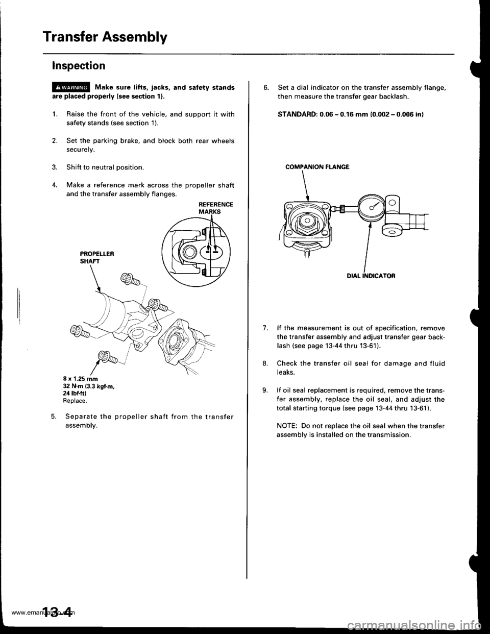
lnspection
@ Make sure tifts, iacks, and satety stands
are placed properly (see section 1).
L Raise the front of the vehicle, and support it with
safety stands (see section 1).
2. Set the parking brake, and block both rear wheels
securely.
3. Shift to neutral oosition.
4. Make a reference mark across the DroDeller shaft
and the transfer assembly flanges,
REFERENCE
8 x 1.25 mm32 N.m (3.3 kg{.m.24 rbf.ftlReplace.
Separate the propeller shaft from the transfer
assemDty.
5.
13-4
6. Set a dial indicator on the transfer assembly flange,
then measure the transfer gear backlash.
STANDARD: 0.06 - 0.16 mm (0.002 - 0.006 in)
COMPAf{ION FI-ANGE
1.lf the measurement is out of specification, remove
the transfer assembly and adjust transfer gear back-
lash (see page 13-44 thru '13-61).
Check the transfer oil seal for damage and fluid
teaKs.
lf oil seal replacement is required, remove the trans-
fer assembly, replace the oil seal, and adjust the
total starting torque (see page 13-44 thru 13-61).
NOTE: Do not replace the oil seal when the transfer
assembly is installed on the transmission.
www.emanualpro.com
Page 451 of 1395
Transmission Assembly
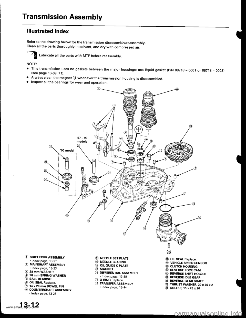
lllustrated Index
Refer to the drawing below for the transmission disassembly/reassembly.Clean all the pans thoroughly in solvent, and drv with comoressed air.
I LuUri""r" utt the parts with MTF before reassembly.
NOTE:
t This transmission uses no gaskets between the major housings; use liquid gasket (p/N 0g718 - 0001 or oE7l8 - 0003)(see page 13-69, 71).. Always clean the magnet @ whenever the transmissjon housing is disassembled.. Inspect all the bearings for wear and operation.
C) sHrFr FoRK ASSEMBLY.Index page, l3-21(a MAINSHAFT ASSEMBLY.Index page, 13-23(9 28 mm WASHER€) 28 mm SPRTNG WASHERO BALL BEARINGa6) OIL SEAL ReDlace.(D 14 x 20 mm DOWEL ptN
G) couNTERSHAFT ASSEMBLY.lndex page, 13-28
NEEDLE SET PLATENEEDLE BEARINGOIL GUIOE C PLATEMAGNETDIFFERENTIAL ASSEMBLY.lndex page, 13-38O-nlNG Beplace.TRANSFER ASSEMBLY.Index page, '13,44
OIL SEAL Replace.VEHICLE SPEED SENSORCLUTCH HOUSINGREVERSE LOCK CAMREVEESE SHIFT HOLDERREVERSE IDLE GEARREVERSE GEAR SHAFTTHRUST WASHER,20 x 36 x 2COLLER, 15 x 20 x 20
aol
@o@@
(D
i9
@@@(9
@@@e3@
13-12
www.emanualpro.com
Page 499 of 1395
Transfer Assembly
Reassembly (cont'd)
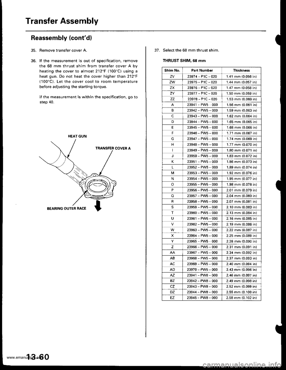
Remove transfer cover A.
lf the measurement is out of specification, remove
the 68 mm thrust shim from transfer cover A by
heating the cover to almost 212'F (100'C) using a
heat gun. Do not heat the cover higher than 212F
(100"C). Let the cover cool to room temperature
before adjusting the starting torque.
lI the measurement is within the specification, go to
step 40.
COVER A
BEARING OUTER RACE
35.
36.
HEAT GUN
13-60
37. Select the 68 mm thrust shim.
THRUST SHIM, 68 mm
Shim No.Part NumberThickne3s
zv23914-P1C-0201.41 mm (0.056 in)
zw23975-P1C-020'1.44 mm 10.057 in)
zx23916 PlC -020'1.47 mm (0.058 in)
ZI23917 -P1C-O201.50 mm (0.059 in)
zz23978-PlC-0201.53 mm (0.060 in)
23941 - PW5 0001.56 mm {0.061 in)
23942-PWs-0001.59 mm (0.063 in)
c23943-PW5-000't.62 mm (0.064 in)
D23944 PW5 - 0001.65 mm (0.065 in)
E23945-PWs-0001.68 mm (0.066 in)
F23946-PW5-0001.71 mm 10.067 in)
G23947-PW5-000'1.74 mm 10.069 in)
23948-PWs-0001.77 mm (0.070 in)
23949-PWs-0001.80 mm (0.071 in)
239s0-PW5-0001.83 mm (0.072 in)
K23951 - PW5 - 0001.86 mm (0.073 in)
L23952-PWs-0001.89 mm {0.074 in)
239s3-PWs-0001.92 mm {0.076 ini
N23954-PW5-0001.95 mm (0.077 in)
o23955-PW5-0001.98 mm (0.078 in)
P23956 - PW5 , 0002.01 mm (0.079 in)
o23957-PWs-0002.04 mm (0.080 in)
R23958-PWs-0002.07 mm (0.081 in)
23959-PW5-0002.10 mm (0.083 in)
T23960-PW5-0002.13 mm (0.084 in)
U23961 - PW5 - 0002.16 mm (0.085 in)
23962-PW5-0002.19 mm (0.086n)
23963-PWs-0002.22 mm (0.087n)
X23964-PWs-0002.25 mm (0.089n)
23965,PWs-0002.28 mm 10.090n)
23966-PW5-0002.31 mm {0.091 in)
23967-PWs-0002.34 mm (0.092 in)
AB23968-PWs-0002.37 mm (0.093 in)
AC23969-PWs-0002.40 mm {0.094 in}
AD23970-PW5-0002.43 mm (0.096 in)
M23941 - PW8 - 0002.46 mm {0.097 'n}
BZ23942-PW8-0002.49 mm (0.098 in)
cz23943-PW8-0002.52 mm {0.099 ini
DZ23944-PW8-0002.55 mm (0.100 in)
EZ23945-PW8-0002.58 mm (0.102 ini
www.emanualpro.com
Page 500 of 1395
38. Install the 68 mm thrust shim using the special
tools.
DRIVER077€ - 001(xno
THRUST S1{IM,68 mmSelective part
BEARING OUTER BACE
ATTACHMENT.62x68mm077a6 - (x)10500
39.After replacing the 68 mm thrust shim, recheck and
make sure the total starting torque is within the
soecification.
40. Coat the new O-rings with MTF, install them on
transfer covers A and B, then install the covers on
the transfer housing.
6x1.0mm12 N.m 11.2 kgf.m,8.7 tbt.ft)TRANSFER COVER B
TRANSFER
O.RINGReplace.
O.BINGReplace.
TRANSFERCOVER A
8 r 1.25 mm2,r N.m (2.4 kgl.m. 17 lbtft)
13-61
www.emanualpro.com
Page 501 of 1395
Mainshaft Bearing/Oil Seal
Replacement
1. Remove the ball bearing using the specialtool.
3/8" -16 SLIDE HAMMER(Commercially available)
PULLER.25 - ,10 mm07736 - A01000A
2. Remove the oil seal from the clutch housing.
13-62
BALL BEARING
3. Drive the new oil seal in from the transmission side
using the special tools.
ATTACHMENT,12x 17 .nfi07746 - 0010300
Drive the new bali bearing in from the transmission
side using the special tools.
ATTACHMENT.62x68mm07746 - 0010500
www.emanualpro.com
Page 502 of 1395
Gountershaft Bearing
Replacement
1. Remove the retaining plate from the clutch housing.
CLUTCH HOUSING
HETAINING PLATE
Remove the needle bearing using the special tool,
then remove the oil guide plate.
Replace.
3/8" -16 SLIDE HAMMER(Commercially available)
CLUTCH TIOUSING
^'ADJUSTABI.f BEARINGPULLER,25 - 40 mm07736 - A01(x)04
NEEDLE BEARING
Position the oil guide plate.
Drive the needle bearing using the special tools.
ATTACHMENT,62x88mm07746- 0t!105q)
NEEDII AEARING
Install the retaining plate, and stake the bolt heads
into the groove in the retaining plate
6x1.0mm12 N.m (1.2 kgt m,8.7 lbtftl
13-63
www.emanualpro.com