Page 1159 of 1395

A/C Compressor Belt
Adjustment
Detlection Method
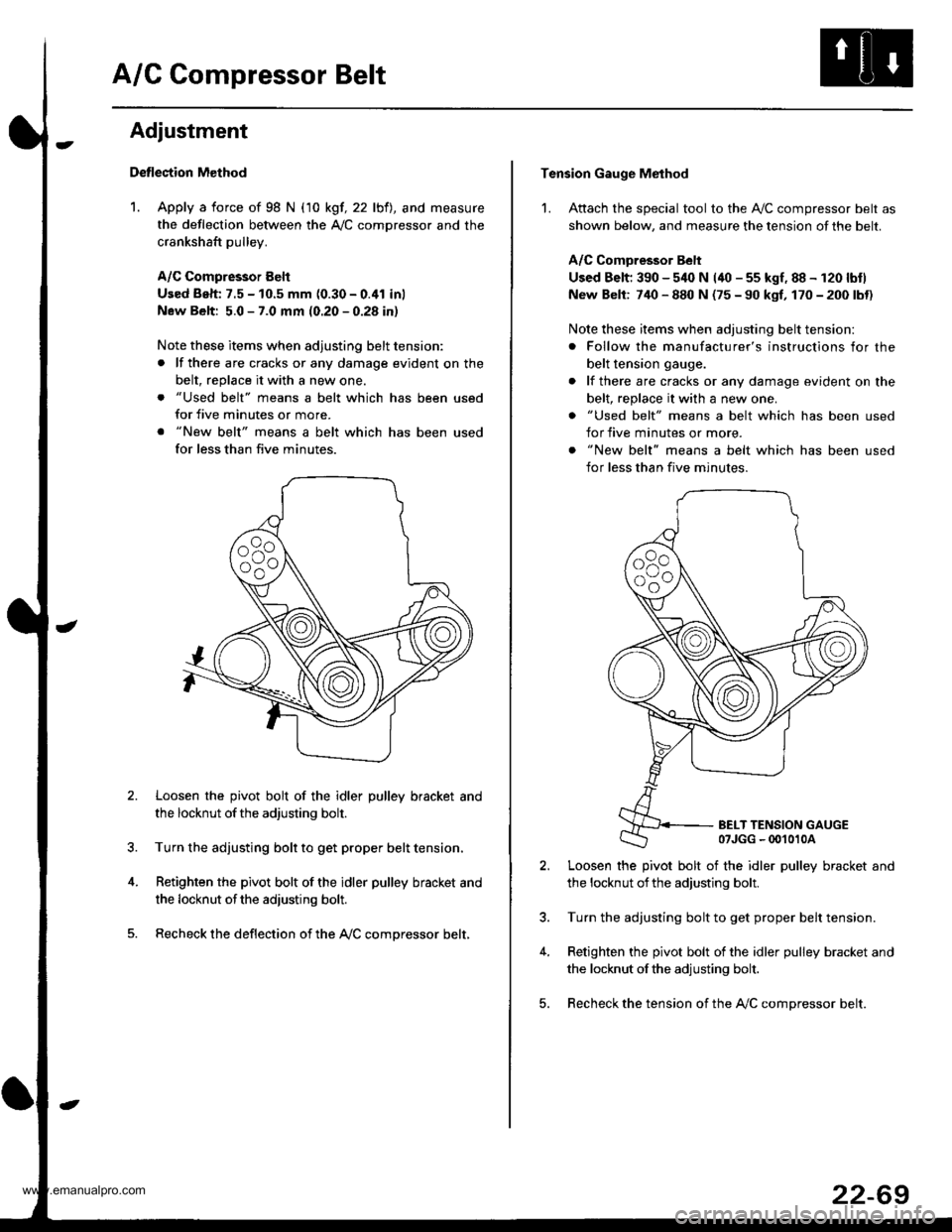
1. Apply a force of 98 N (10 kgf, 22 lbfl, and measure
the deflection between the A,/C comDressor and the
crankshaft pulley.
A/C Compressor Eelt
Used Beh: 7.5 - 10.5 mm (0.30 - 0.41 inl
New Belt: 5.0 - 7.0 mm (0.20 - 0.28 in)
Note these items when adjusting belt tension:
. lf there are cracks or any damage evident on the
belt, replace it with a new one.
. "Used belt" means a belt which has been used
for five minutes or more.
. "New belt" means a belt which has been used
for less than five minutes.
Loosen the pivot bolt of the idler pulley bracket and
the locknut ofthe adjusting bolt.
Turn the adjusting bolt to get proper belt tension,
Retighten the pivot bolt of the idler pulley bracket and
the locknut ofthe adiusting bolt.
Recheck the deflection of the A,/C compressor belt,
Tension Gauge Method
1. Attach the special tool to the Ay'C compressor belt as
shown below, and measure the tension of the belt.
A/C Comoressor Belt
Used Belt; 390 - 540 N (40 - 55 kgf, 88 - 120 lbtl
New Belt: 740 - 880 N (75 - 90 kgf, 170 - 200 lbt)
Note these items when adjusting belt tension:
. Follow the manufacturer's instructions for the
belt tension gauge.
. lf there are cracks or any damage evident on the
belt, replace it with a new one.
. "Used belt" means a belt which has been used
for five minutes or more.
. "New belt" means a belt which has been used
for less than five minutes.
BELT TENSION GAUGE07JGG - 00't010A
Loosen the pivot bolt of the idler pulley bracket and
the locknut ofthe adjusting bolt.
Turn the adjusting bolt to get proper belt tension.
Retighten the pivot bolt of the idler pulley bracket and
the locknut ofthe adjusting bolt.
Recheck the tension of the A,/C compressor belt.
22-69
www.emanualpro.com
Page 1163 of 1395

Troubleshooting
Tips and Precautions
Bef ore Troubleshootin g
. Check applicable fuses in the appropriate fuse/relay
box.
. Check the battery for damage, state of charge, and
clean. and tight connections.
. Check the alternator belt tension.
CAUTION:
. Do not quick-charge a battery unless the battery
ground cable has been disconnected, otherwise you
will damage the alternator diodes.
. Do not attempt to crank thc engins wilh the battery
ground cable loosely connected or you will severely
damage the wiring.
Handling Connestors
. Make sure the connectors are clean and have no loose
wire terminals,
. N4ake sure multiple cavity connectors are packed with
grease (except water-tight connectors).
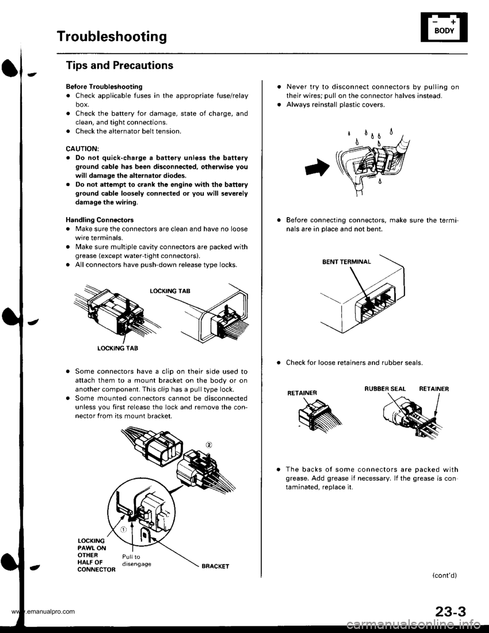
. All connectors have push-down release type locks.
Some connectors have a clip on their side used to
attach them to a mount bracket on the body or on
another component. This clip has a pull type lock.
Some mounted connectors cannot be disconnected
unless you first release the lock and remove the con-
nector from its mount bracket.
LOCKINGPAWL ONOTHERHALF OFPulltodisengage
LOCKING TAB
CONNECTORBRACKET
Never try to disconnect connectors by pulling on
their wires; pull on the connector halves instead.
Alwavs reinstall olastic covers.
Before connecting connectors, make sure the termi-
nals are in place and not bent.
. Check for loose retainers and rubber seals.
RETAINER
The backs of some connectors are oacked with
grease. Add grease if necessary. lf the grease is con
taminated. reolace it.
{cont'd}
23-3
www.emanualpro.com
Page 1174 of 1395
![HONDA CR-V 1999 RD1-RD3 / 1.G Workshop Manual
Connector ldentification and Wire Harness Routing
Engino Wire Harness
Connecto; or
Terminal
Number of
CavitiesLocationConneqts toNotos
c101
c102
c103
c 104
c105
c105
c106
c 107
c 108
c 109
c]10
c1ll HONDA CR-V 1999 RD1-RD3 / 1.G Workshop Manual
Connector ldentification and Wire Harness Routing
Engino Wire Harness
Connecto; or
Terminal
Number of
CavitiesLocationConneqts toNotos
c101
c102
c103
c 104
c105
c105
c106
c 107
c 108
c 109
c]10
c1ll](/manual-img/13/5778/w960_5778-1173.png)
Connector ldentification and Wire Harness Routing
Engino Wire Harness
Connecto; or
Terminal
Number of
CavitiesLocationConneqts toNotos
c101
c102
c103
c 104
c105
c105
c106
c 107
c 108
c 109
c]10
c1l'l
c112
c113
c't 14
cl16
cl16
c117
c118
c119
c120
c121
c't22
c't23
c't25
cl26
cl27
cr 28
cl29
c130
c131
c132
c 133
c134
c134
c135
c 136
10
6
1
2
1
2
1
10
20
31
16
22
l0
l0'14
14
1
Left side of engine compartment
Left side of engine compartment
Middle of engine
Middle of engine
Left side of engine compartment
Left side of engine compartment
Middle of engine
Middle of engine
Middle of engine
Middle of engine
Middle of engine
Middle of engine
Middle of engine
Middle of engine
Middle of engine
Middle of engine
Middle of engine
Middle of engine
Middle of engine
Middle of engine
Middle of engine
Right side of engine
Middle of engine
Behind right kick panel
Under right side of dash
Under right side of dash
Under right side of dash
Under right side of dash
Under right side of dash
Right side of engine
Right side of engine
Middle of engine
Middle of engine
Middle of engine
Middle of engine
Middle of engine
Middle of engine
Left side of engine compartment
Middle of engine
Middle of engine
Main wire harness (C304)
Main wire harness (C305):'97 - 98 models
No. 1 fuel injector
Crankshaft speed fluctuation (CKF) sensor
Alternator
Alternator
Engine oil pressure switch
No.2 fuel injector
Evaporative emission (EVAP) purge
control solenoid valve
No. 3 fuel injector
No. 4 fuel injector
Primary heated oxygen sensor(Primary HO2S) (sensor 1)
Radiator fan switch
Coolant temperature sending unit
Engine coolant temperature (ECT) sensor
Mainshaft speed sensor
Lock-up control solenoid valve
Back-up light switch
Shift control solenoid valve
Linear solenoid valve
Countershaft speed sesnsor
Starter solenoid
Distributor
Junction connector
PCM
ECIWPCM
ECM/PCM
ECM/PCM
Main wire harness (C,|:}1)
IVT gear position switch
Vehicle speed sensor (VSS)
Throttle position (TP) sensor
MAP sensor
ldle air control (lAC)valve
lntake air temperature (lAT) sensor
Junction connector
Junction connector
Power steering pressure (PSP) switch
Junction connector
Knock sensor (KS)
A/r
USA
Canada
Alr
AlT
M/'r
Afi
'97mooel
'97 model'98 - 00
mooets
'99 - 00
models
T101
r102
Left side of en0ine companment
Right side of engine compartment
Alternator
Under-hood fuse/relay box
G101Middle of engineEngine ground, via engine wire harness
23-14
www.emanualpro.com
Page 1211 of 1395
(},
J-
BATTERY CODE
i
5582{LtS)-MF
J
Charge on High Setting (40 amps)
Charge until EYE shows charge is OK, plus an additional 30 minutes to
assure Jull charge.
NOTE: lf the battery charge is very low, it may be necessary to bypass
the charger's polarity protection circuitry.
lf the EYE does not show charge is OK within three hours, the battery is
no-good; replace it. Write down how long the battery was charged.
Test Load Capacity (#2)
. Apply 300 amp load for 15 seconds to remove surface charge.
. Allow 15 Seconds recovery period,
. Apply test load (see Test Load Chart).
. Record voltage at the end ot 15 seconds.
Voltage drops below 9.6 volts;
battery is no-good,Voltage stays above 9.6 volts;
battery is OK.
TEST LOAD CHART
Use the test load or use 1/2 the cold cranking amps (CCA) printed on
the label on the top of the battery. lf neither is indicated. use the infor-
mation below:
BATTERY
CODE
COLD CRANKING
AMPS (CCA)
TEST LOAD
{amps)
55410200
J
23-51
www.emanualpro.com