Page 1335 of 1395
Troubleshooting
The SRS Indicator Light Doesn't Go Off - '97 model (cont,d)
From page 24 37(A)
SRS MAIN HARNESS 18P CONNECTOR
(B)To page 24'39
DASHBOARD WIRE HARNESS5P CONNECTOR
(c)To page 24-40
DASHBOAND WIRE HARI{ESS5P CONNECTOR
)
J
c509
Wire side ol femaleterminals
T
Check the SRS unit:Connect the SRS main harness 18P connector terminals No.6 and No.7 with a jumper wire and backprobe
Faulty SRS unit or poo. contact at the SRS main ha.ness18P connectoi; check the connector.lfthe conneqtor is OK, replace the SRS unit.
Oid tuse No. 13 (15 Al blow?
Check for a short to ground in the SRS indicator tight cir-cutl:1. Turn the ignitlon switch oFF.2, Disconnect the dashboard wire harness 5p connectorfrom the gauge assembly.3. Check resistance between the No. 1 terminal ofthe dashboard wire harness 5P connector and ground. Thereshould be 1 MO or more.
Shon to ground in th6 gaugo assembly; replaco the gau96
JUMPER WIRE
Wlre sido ot tomale terminsls
243a
--
www.emanualpro.com
Page 1336 of 1395
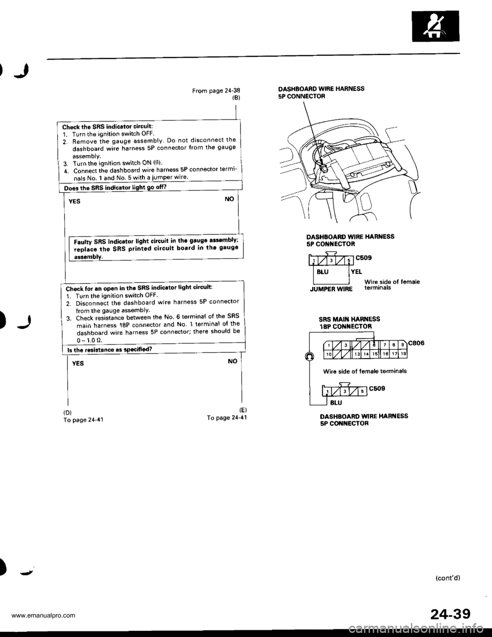
Check lhe SRS indicalor circuit:
1. Turn the ignition switch OFF
2. Remove the gauge assembly Do not disconnect the
dashboard wire harness 5P connector from the gauge
assemoly.3. Turn the ignition switch ON (ll).
4. Connect tie dashboard wire harness 5P connector termi-
nals No. I and No 5 with a iumper wire.
Does the SRS indicator light 90 otn
Faulty SRS indicator light circuit in the 9aug6 a$embly;
reolace the SRS printod circuit boa.d in th' gauge
Check tor rn open in the SRS indicator light circuit:
1. Turn the ignition switch OFF
2. Disconnect the dashboard wire harness 5P connector
from the gauge assemblY.
3. Check res]sta-nce between the No. 6 terminal ol the SRS
main harness 18P connector and No l terminal ol the
dashboard wire harness 5P connector; there should be
From page 24-38{B)
DASHBOARD WIRE HARNESS5P CONNECTOR
DASHBOARD WIRE HARNESS5P CONI{ECTOR
)
Y;yfivvcsosffi
I BLU IYELWir6.side of femaleJUMPER WIRE lormrna|s
SRS MAI HAN ESSt8P CO I{ECTOR
DASHBOARD WIRE HARNESS5P COI{NECTOR
{D)To page 24-41
1E)To page 24-41
)(cont'd)
Wire side oI fsmale terminals
24-39
www.emanualpro.com
Page 1340 of 1395
)
Ftom page 24-42(A)
SRS MAIN HARNESS 18P CONNECTOR
)
1B)fo page 24-44
(c)
To page 24-45
Wire side of lemale lerminals
DASHBOAED WIRE HARNESS5P CONNECTOR
DASHEOARD WIRE HARNESS5P CONNECTOR
c509
)(cont'd)
SRS UNIT
SRS MAIN HARNESS
Check the SRS unit:Connect the SRS main harness 18P connector terminals No.
3 and No. 6 with a iumper wire and backprobe
Does the SRS indicator light go otf?
Faulty SRS unit or poor contact at the SRS main harness
18P connedor; check the connector.lf the connoctor is OK, replace the SRS unit
Did tuse No. 23 {10 A} blow?
Check for a short to ground in the SRS indicator light cir-
curl:1. Turn the ignition switch OFF.
2, Disconnect the dashboard wire harness 5P connector
from the gauge assembly,3. Check resistance between the No l terminal ofthedash-
board wire harness 5P connector and ground. There
should be 1 Mo or more.
Short to ground in the gauge assembly; replace the gauge
JUMPER WIRE
24-43
www.emanualpro.com
Page 1344 of 1395
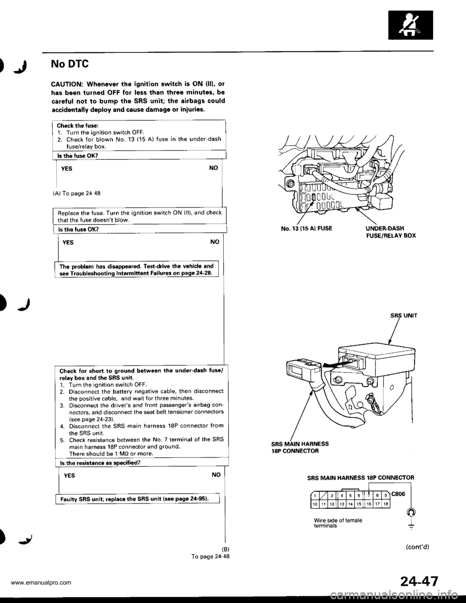
No DTC
CAUTION: Whenever the ignition switch is ON {lll, ol
has been tulned OFF for less than three minutes, bs
careful not to bump the SRS unit; the airbags could
accidenially deploy and cause damago or iniuries.
UNDER-DASHFUSE/RELAY BOX
)
SBS MAIN HARNESS18P CONNECTOR
)(cont'd)(B)
To page 24-48
Ch€ck the fuse:1. Turn the ignition switch OFF.2. Check for blown No. 13 ('15 A) fuse in the under-dashIuse/relay box.
b th€ fuse OK?
YEs NO
1A) To page 24 48
Replace the fuse. Turn the ignition switch ON {ll), and check
that the luse doesn't blow.
ls the fuse OK?
YESNO
The probl€m has disappeared. Ted{rive the v€hicle and
see Troubfeshooting Intermittont Failurea on page 21-28.
Check Ior short to ground between tho underdash tuse/
relay box and the SRS unil.1. Turn the ignition switch OFF.2. Disconnect the battery negative cable, then disconnect
the positive cable, and wait for three min utes.
3. Disconnect the driver's and front passenger's airbag con-
nectors, and disconnect the seat belt tensioner connectors(see page 24-23).4. Disconnect the SRS main harness l8P connector from
the sRs unit.5. Check resistance between the No. 7 terminal of the SRS
main harness 18P connector and ground.
There should be 1 M0 or more.
ls the .esistanco as soecified?
YESNO
Faulty SRS unit; replace lhe SRS unit {see page 24-951.
No. 13 (r5 Al FUSE
SRS MAIN HARNESS 18P CONNECTOR
24-47
www.emanualpro.com
Page 1350 of 1395
From page 24-52
Chock for a shon in th6 cablo recl {cont'dl:5. Reconnect the battery oositive cable, then reconnect thanegative cable.6. Ersse the DTC memory (see page 24-28).7. Read the DTC (see page 24-26l'.
ls DTC 'l-3 indic{tod?
NOYES
Short in the csble reel; replace tha cabls rcol lsao paga
24-911.
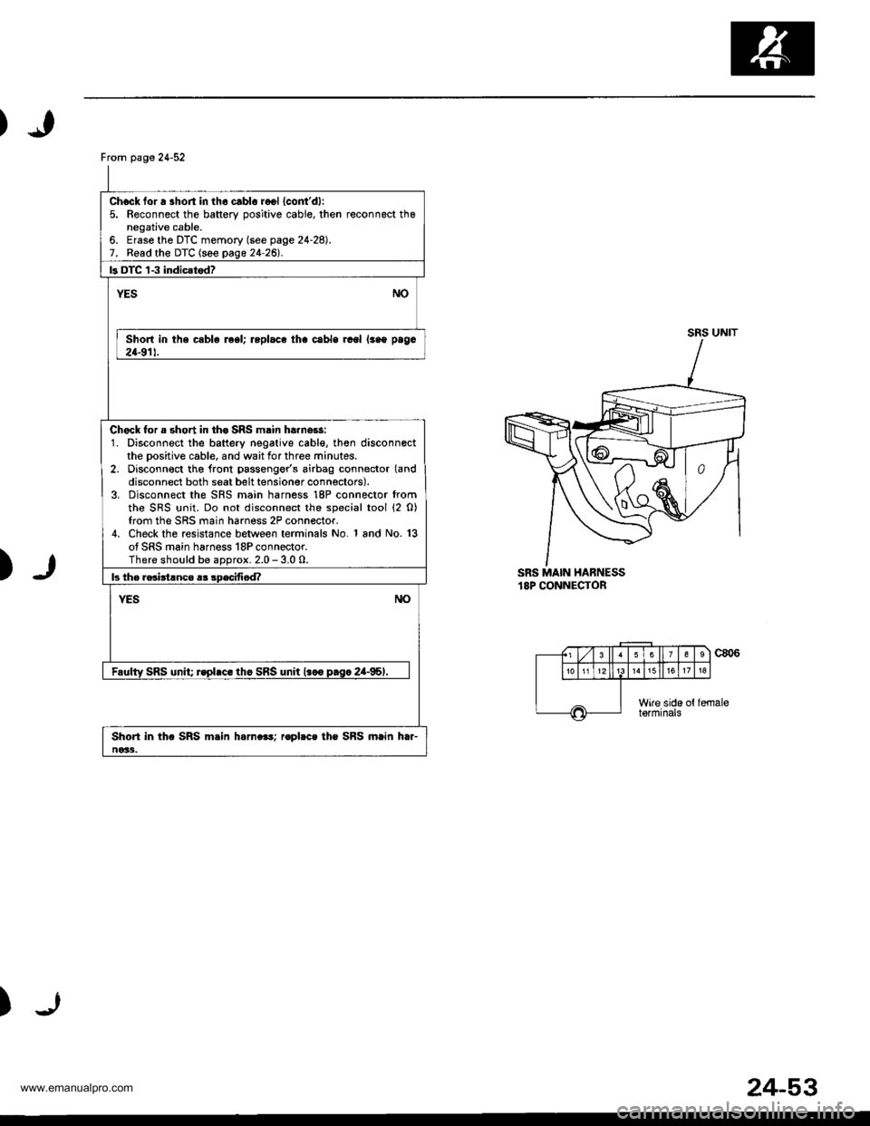
Chock for a short in th€ SRS main ha.nors:1. Disconnect the battery negative cable, th€n disconnectthe Dositive cable, and wait for three minutes.2. Disconn€ct tho lront passengor's airbag connector (and
disconnect both seat belt tensioner connectors).3. Disconnect the SRS main harness 18P connector fromthe SRS {rnit. Do not disconnect the special tool (2 0)from the SRS main harness 2P connector.4. Check the resistance between terminals No. 1 and No. 13of SRS main harness 18P connector.There should be aDorox. 2.0 - 3.0 0.
b th€ rsciitlnce a3 sDecifi6d?
NOYES
Faulty SRS unit; rspl.c. th6 SRS unit l.co p.sc 2a-95,,
Shori in the SRS m.in h.rn.e!; ropbce the SRS main htr-ne33.
SRS UNIT
)SRS MAIN HABNESS18P CONNECTOR
c806
)
(., Lzl 3 ll63
1518
Wire side ottormrnats
24-53
www.emanualpro.com
Page 1352 of 1395
Ftom page24-54
Check for 6 short power in the cable r6el {cont'd):5. Reconnect the battery positive cable, then reconnect thenegative cable.6. Erase the DTC memory (see page 24-28).7. Read the DTC (see page 24-261.
b DTC 1-4 indicarodz
YESNO
Short to power in lhe cablo roel; replace th€ cabl€ ieel{see pago 24-91).
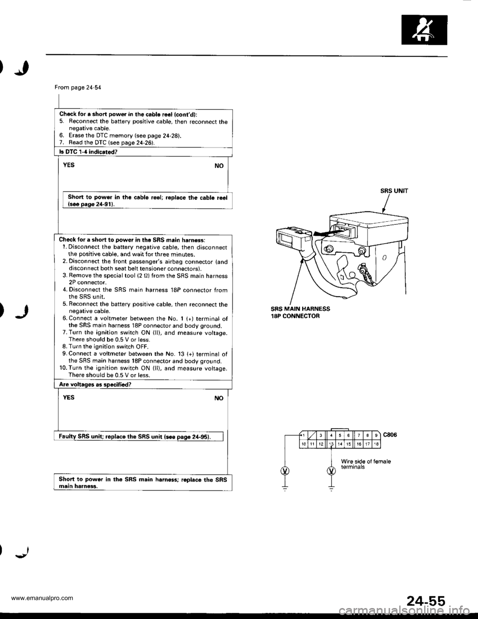
Check tor a short to power in th. SRS main harn$s:1. Disconnect the battery negative cable, then disconnectthe positive cable, and wait for three minutes.2. Disconnect the front passenger's airbag connector {anddisconnect both seat belt tensioner connectors).3. Rernove the special tool (2 O) from the SRS main harness2P connector.4. Disconnect the SRS main harness 18P connector fromthe SRS unit.5. Beconnect the batterv positive cable, then reconnect thenegative cable.6. Connect a voltmeter between the No. 1 {+) terminal olthe SRS main harness 18P connector and body ground.7. Turn the ignition switch ON (ll), and measure voltage.There should be 0.5 V or less.8. Turn the ignition switch OFF.9. Connect a voitmeter between the No. 13 {+i terminal ofthe SRS main harness 18P connector and body ground.10.Turn the ignition switch ON lll), and measure voltage.There should be 0.5 V or less.
Are voltages as specified?
YESNO
Faulty SRS unit; replaco th€ SRS unit lsoo pas6 24-95).
Short to power in th€ SRS main hamoss; roplece the SRSmain haanass.
SRS MAIN HARNESS18P CONNECTOR
24-55
www.emanualpro.com
Page 1358 of 1395
)
SRS MAIN HARNESS18P CONNECTOR
)
)
From page 24 60
Ch6ck tor a short to another wire or decreasod aGsistance inlh€ SRS main harness:1. Disconnect the battery negative cable, then disconnectthe positive cable, and wait for three minutes.2. Disconnect the driver's airbag 2P connector (and disconnectboth seat belt tensioner connectors).3. Disconnect the SRS main harness '18P connector fromthe SRS unit. Do not disconnect the special tool (2 O).4. Check resistance between the No. 10 terminal and No. 14terminal of the SRS main harness 18P connector. Thereshould be aoorox. 2.0 - 3.0 0.
ls the rosistanc6 as specified?
YESNO
Faultv SRS unit; replace lhe SRS unit lsee page 24-95).
Short to anothor wire or decre.sed re3i3t.nce in the SRSmain harness; replac€ the SRS main harn*s.
24-61
www.emanualpro.com
Page 1360 of 1395
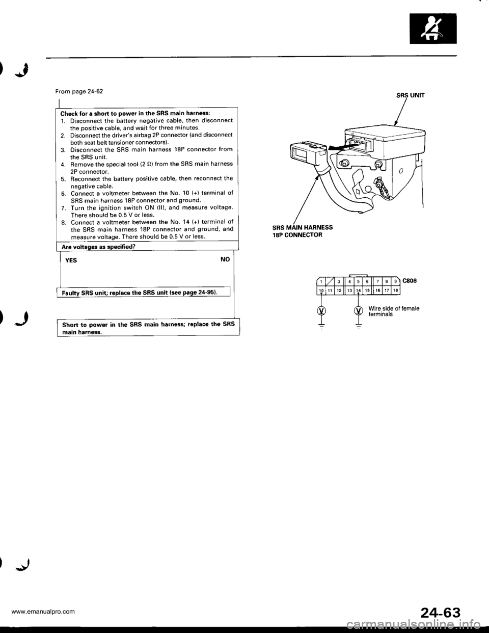
Frcm page24-62
Check lor a short to power in the SRS main harness:
1. Disconnect the battery negative cable, then disconnectthe positive cable, and wait for three minutes.
2. Disconnect the drive/s airbag 2P connector (and disconnect
both seat belttensionerconnectors).3. Disconnect the SRS main harness 18P connector trom
the SRS unit.4. Remove the specialtool (2 0) from the SRS main harness
2P connector,5. Reconnect the batterv positive cable, then reconnect the
negative cable.6. Connect a voltmeter between the No. 10 (+) terminal of
SRS main harness 18P connector and ground.
7. Turn the ignition switch ON (ll). and measure voltage
There should be 0.5 V or less.8. Connect a voltmeter between the No. 141+) terminal of
the SRS main harness 18P connector and ground, and
measure voltage. There should be 0.5 V or less.
Are voltages .3 specifiedT
YESNO
Faulty SRS unit; replace the SRS unit (sce page 24'95).
Short to powor in the SRS main ha.ne3s; replace the SRS
main hdrness.
sRs.I8P CONNECTOR
24-63
www.emanualpro.com