Page 863 of 1395

Steering Wheel
Removal
SRS components are located in this area. Review the
SRS component locations, precautions, and procedures
in the SRS section (24) before performing repairs or ser-
vice.
1. Align the front wheels straight ahead. then remove
the driver's airbag assembly (see section 24) from
the steering wheel.
2. Disconnect the horn connector and cruise control
switch connectors.
CONTROLSWITCHES CONNECTOR
3. Loosen the steering wheel bolt, then install a steering
wheel puller on the steering wheel and remove it.
Note these items when removing the steering wheel:
. Do not tap on the steering wheel or the steering
column shaft when removing the steering wheel.
. lf you thread the puller bolts into the wheel hub
more than five threads, the bolts will hit the cable
reel and damage it. To prevent this, install a pair
of jam nuts five threads up on each puller bolt.
STEERING WHEEL BOLT39 N.m 14.0 kgt.m,29 lbtftl
STEERING WHEEL EOLT
Disassembly/Reassembly
EOSS COVER PLATE
_^M
STEERING WHEEL
WHEEL BODY COVER
17-18
@,
ACCESS PANEL
h"\
BODYCOVER CAP
www.emanualpro.com
Page 864 of 1395
lnstallation
1. Before installing the steering wheel, make sure the
front wheels are aligned straight ahead, then center
the cable reel. Do this by first rotating the cable reel
clockwise until it stops. Then rotate it counterclock-
wise approximately two turns. The arrow mark on
the cable reel label should point straight up.
ARROW MARK
2. Install the steering wheel on to the steering column
shaft, making sure the steering wheel shaft engages
the cable reel and canceling sleeve. Do not tap on
the steering wheel or steering column shatt when
instailing the steering wheel
HOLE
Install the steering wheel bolt, and tighten it to 39
N.m (4.0 kgf.m, 29 lbf.ft).
Connect the horn connector and the cruise control
switch connectors,
Install the driver's airbag assembly, and confirm
proper system operation (see section 24).
CABLE REEL
17-19
www.emanualpro.com
Page 865 of 1395

Steering Column
Removal/lnstallation
SRS components are located in this area. Review the
SRS component locations, precautions, and procedures
in the SRS section (24) before performing repairs or ser-
vice.
Note these items when removing the steering column:. Before removing the steering column, remove thedriver's airbag assembly and cable reel (see section24).
. Before removing or installing, set the column shaft inthe neutral position by pulling up the steering columnto uppermost position, then lower it 8 mm (5/16 in).Tighten tilt lever.
FULL STROKE:23 mm 10.9 in)
MAXIMUM UPPER8 mm (5/16)
POSTTTON
Remove the steering wheel (see page 17-18).
Remove the driver's side dashboard lower cover
and knee bolster (see section 20),
Remove the column covers.
With A"/T, move the shift lever to the E position,
and remove the shift cable from the column. andset it aside (see section 14).
Remove the combination switch assembly from thesteering column shaft by disconnecting the connec-
tors, and removing the two screws.
Disconnect the steering joint from the engine com-panment.
Remove the steering column by removing theattaching nuts and bolts.
7.
1.
MAXIMUM LOWERPOSTTTON
SHAFT CENTER
111 mm 100 mm5mm
JOINT COVERBOOT BAND
9,8 N.m l r .0 kgf.m, 7 lbf.fO
JOINT DUST SEAL
22 N.m (2.2 kgl.m, 16lbtftl
TILT LEVER
UPPER ATTACHING NUTS16 N.m lr.6 kgf.m, 12 lbf.ftl
UPPER COLUMN COVER
COMAINANON SWITCH ASSEMBLY
JOINT
COLUMN BMCKET
LOWER ATTACHING BOLTS39 N.m lir,o kgf.m, 29 lbf.ft)
17-20
LOWER COLUMN COVER
www.emanualpro.com
Page 876 of 1395

Power Steering Gearbox
Removal
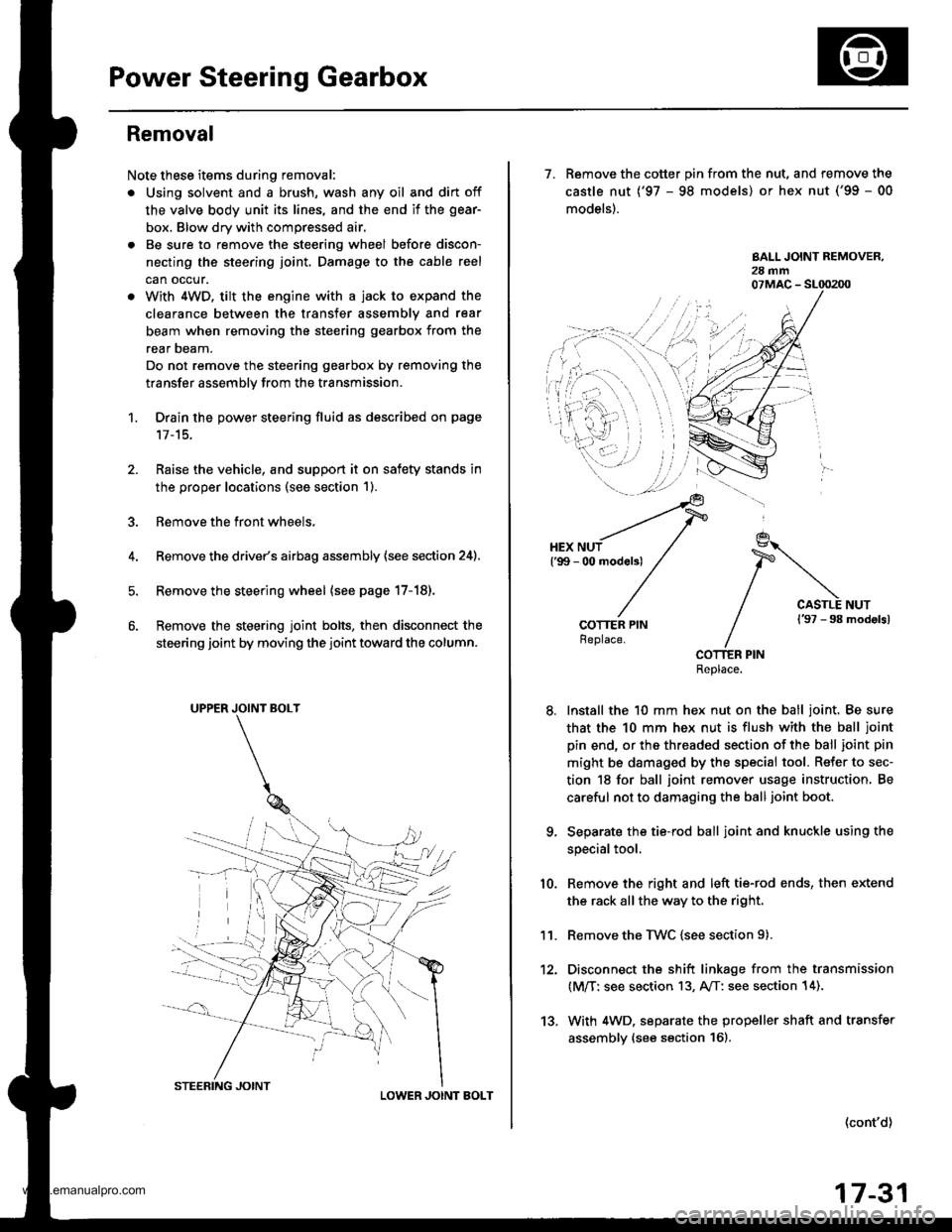
Note these items during removal:
. Using solvent and a brush, wash any oil and dirt off
the valve body unit its lines, and the end if the gear-
box. Blow dry with compressed air.
. Be sure to remove the steering wheel before discon-
necting the steering joint. Damage to the cable reel
can occur.
. With 4WD. tilt the engine with a jack to expand the
clearance between the transfer assembly and rear
beam when removing the steering gearbox from the
rear oeam.
Do not remove the steering gearbox by removing the
transfer assembly from the transmission.
1. Drain the power steering fluid as described on page'17-15.
Raise the vehicle, and suppon it on safety stands in
the proper locations (see section 1).
Remove the front wheels,
Remove the drive/s airbag assembly {see section 24).
Remove the steering wheel {see page 17-18).
Remove the steering joint bolts, then disconnect the
steering joint by moving the joint toward the column.
UPPER JOINT BOLT
LOWER JOINT BOLT
13.
7. Remove the cotter pin from the nut, and remove the
castle nut {'97 - 98 models) or hex nut ('99 - 00
models).
COTTER PINReplace.
Install the 10 mm hex nut on the ball joint. Be sure
that the 10 mm hex nut is flush with the ball joint
pin end, or the threaded section of the ball joint pin
might be damaged by the special tool. Refer to sec-
tion 18 for ball joint remover usage instruction, Be
careful not to damaging the ball joint boot.
Separate the tie-rod ball joint and knuckle using the
special tool.
Remove the right and left tie-rod ends, then extend
the rack all the way to the right.
Remove the TWC (see section 9).
Disconnect the shift linkage from the transmission
(M/T: see section 13, A/T: see section 14).
With 4WD. separate the propeller shaft and transfer
assembly (see section 161.
10.
11.
(cont'd)
17-31
www.emanualpro.com
Page 919 of 1395

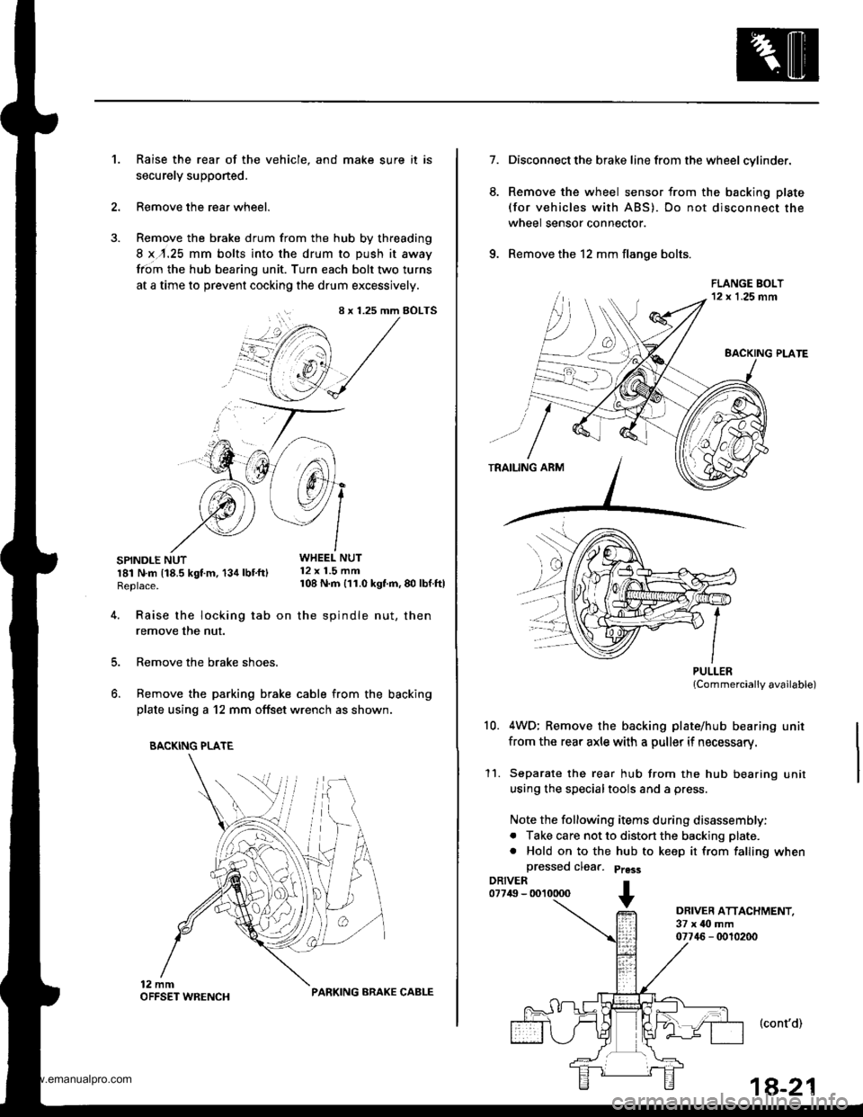
Raise the rear of the vehicle, and make sure it is
securely supponed.
Remove the rear wheel.
Remove the brake drum from the hub by threading
8 x,r.25 mm bolts into the drum to push it away
from the hub bearing unit. Turn each bolt two turns
at a time to prevent cocking the drum excessively.
SPINDLE NUTWHEEL NUT
r81 N.m t18.5 kgt m, 134 lbt'ftl 12 x 1.5 mm
Replace. 108 N m 111.0 kgf'm, 80 lbf ftl
't.
4.
8 x 1.25 mm BOLTS
i+/3 /',1
"@,1 /
.'--7 J-->-
5.
6.
Raise the locking tab on the spindle nut, then
remove the nut.
Remove the brake shoes.
Remove the parking brake cable from the backing
plate using a 12 mm offset wrench as shown.
BACKING PLATE
PARKING ARAKE CABLE
1a-21
7.
6.
Disconnect the brake line from the wheel cylinder.
Remove the wheel sensor from the backing plate
(for vehicles with ABS). Do not disconnect the
wheel sensor connector.
Remove the 12 mm flange bolts.
PULLERlCommercially available)
4WD; Remove the backing plate/hub bearing unit
from the rear axle with a puller if necessary.
Separate the rear hub from the hub bearing unit
using the specialtools and a press.
Note the following items during disassembly:
. Take care not to distort the backing plate.
. Hold on to the hub to keep it from falling when
a
10.
11.
DRIVER ATTACHMENT,37 x ilo mm07746 - 0010200
(cont'd)
www.emanualpro.com
Page 925 of 1395

Brakes
Special Tools ............. 19-2
Component Locations
lndex ................ ...... 19-3
Inspection and Adlustment
Brake System Rubber Parts
and Brake Booster ..........,,,.......... 19-4
Brake Pedal ............ 19-5
Parking Brake ........ 19-6
Bleeding ................. 19'7
Brake System Indicator ................... 19-8
Front Brake Pads
Inspection and Replacement .......... 19-9
Front Brake Disc
Disc Runout Inspection ................... 19-11
Disc Thickness and
Parallelism Inspection ........,........ 19-1 1
Front Brake Caliper
Disassembly/Reassembly ............... 19-12
Master Cylinder/Brake Booster
Removal/lnstallation ....................... 19-13
Master Cylinder
Inspection/Disassembly .............. 19-14
Pushrod Clearance Adiustment ...... 19-14
Brake Booster Inspection ...,.,,,,....... 1 9-1 5
Rear Drum Brakes
Inspection .............. 19-15
Brake Shoes
Replacement ..... 19-r 8
Wheel Cylinder Replacement ......... 19-20
Brake Hoses/Lines
Inspection/Torque Specifications ... 19-21
Hose Replacement ....,...,............. ..,,, 19-22
Parking Brake Cable
Inspection and Replacement .......... 19-23
www.emanualpro.com
Page 942 of 1395

Rear Drum Brakes
Brake Shoes Replacement
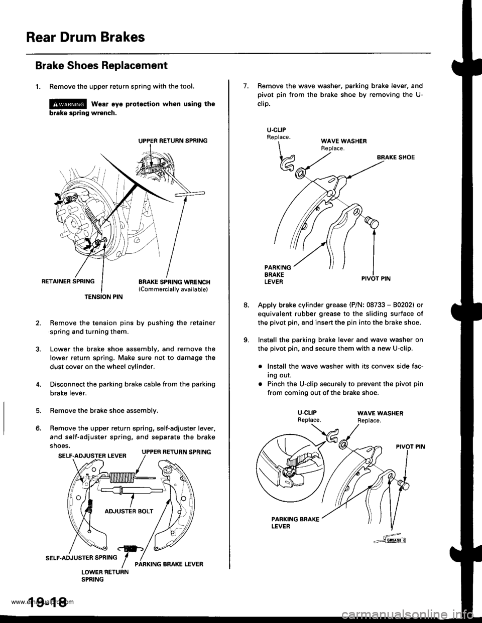
1. Remove the upper return spring with the tool.
l@ w€ar eye protestion when using the
brske spring wrench.
RETAINER SPRINGBRAKE SPRING WBENCH{Commerciallv available)
Remove the tension pins by pushing the retainer
spring and turning them.
Lower the brake shoe assembly, and remove the
lower return spring, Make sure not to damage the
dust cover on the wheel cylinder,
Disconnect the parking brake cable from the parking
brake lever.
Remove the brake shoe assembly,
Remove the upper return spring, self-adjuster lever,
and self-adjuster spring, and separate the brake
shoes.
TENSION PIN
5.
o.
SELF.ADJUSTER LEVER UPPER RETURN SPRING
19-18
7. Remove the wave washer, parking brake lever. and
pivot pin from the brake shoe by removing the U-
cliD.
BRAKE SHOE
Apply brake cylinder grease (P/N: 08733 - 80202) or
equivalent rubber grease to the sliding surface of
the pivot pin, 8nd insert the pin into the brake shoe.
Install the parking brake lever and wave washer on
the pivot pin, and secure them with a new U-clip.
. lnstall the wave washer with its convex side fac-
Ing our.
. Pinch the U-clip securely to prevent the pivot pin
from coming out of the brake shoe.
U.CLIPReplace.
\\
w
U-CLIPReplace.WAVE WASHERReplace.
www.emanualpro.com
Page 943 of 1395

10.
11,
Connect the parking brake cable to the parking
brake lever,
Clean the threaded portions of clevises A and B.
Coat the threads of the clevises with grease. To
shorten the clevises, turn the adiuster bolt.
Hook the self-adjuster spring to the self-adjuster
lever first, then to the brake shoe,
Install the clevises and upper return spring noting
the installation direction. Be careful not to damage
the wheel cylinder dust covers.
Installthe lower return spring.
12.
14.
UPPER RETURN SPRING
Apply rubber greaseto sliding surface.
15. Apply grease on each sliding surface. Keep grease
or oil off the brake linings. Wipe any excess grease
off the parts.
. Apply brake cylinder grease (P/N: 08733 - 8020E)
or equivalent rubber grease to the sliding sur-
faces as shown.
..4 Slrdrng surface
Apply Molykote 44MA to the brake shoe ends
and opposite edges of the shoes as shown.
.. a Opposite edge of the shoe.: a) Brake shoe ends(Shoe side ends and backingplate contact surface)
(cont'd)
www.emanualpro.com