1999 HONDA CR-V Fuel system
[x] Cancel search: Fuel systemPage 426 of 1395

Emission Control System
Evaporative Emission (EVAP) Controls (cont,dl
Evaporative Emission (EVAP) Two Way Valve Testing
'97 model:
1. Remove the fuelfill cap.
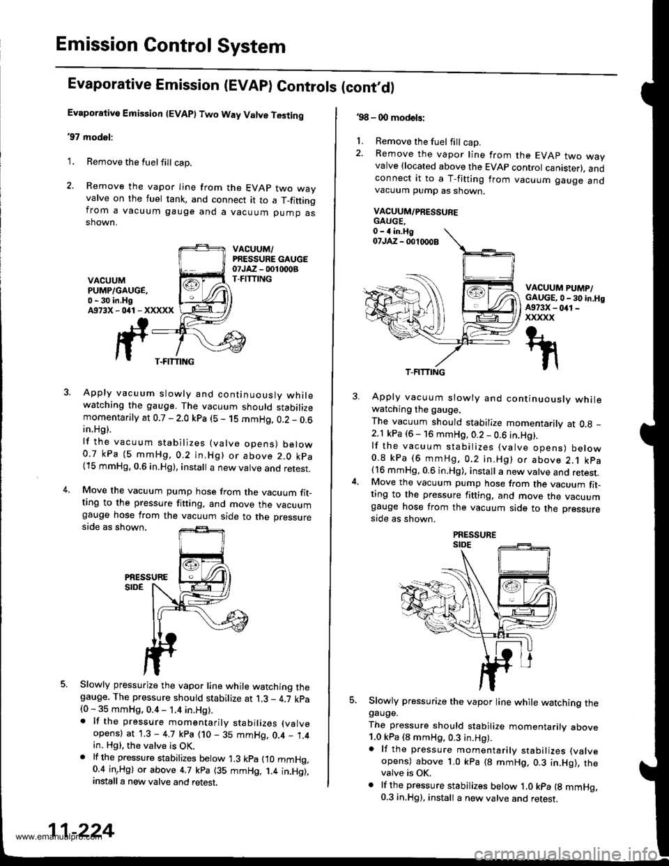
2. Remove the vapor Iine from the EVAP two wayvalve on the fuel tank, and connect it to a T_fittingfrom a vacuum gauge and a vacuum pump asshown.
VACUUM,/PRESSURE GAUGEotJAz - 001 rDoBT-FITTINGVACUUMPUMP/GAUGE,0 - 30 in.HgA973X-041-XXXXX
3. Apply vacuum slowly and continuouslv whilewatching the gauge. The vacuum should stabilizemomentarily at 0.7 - 2.0 kpa (5 - 1S mmHg, 0.2 _ 0.6in.Hg).
lf the vacuum stabilizes (valve opens) below0.7 kPa (5 mmHg,0.2 in,Hg) or above 2.0 kpa(15 mmHg, 0.6 in.Hg), install a new valve and retest.
4.Move the vacuum pump hose from the vacuum fit_ting to the pressure fitting, and move the vacuumgauge hose from the vacuum side to the pressureside as shown.
PiESSURESIDE
5. Slowly pressurize the vapor line while watching thegauge. The pressure should stabilize at 1.3 - 4.7 kpa(0 - 35 mmHg, 0.4 - 1.4 in.Hg).. lf the pressure momentarily stabilizes (valve
opens) at 1.3 - 4.7 kpa (10 - 35 mmHg, 0.4 _ 1.4in. Hg), the valve is OK.. lf th6 pressure stabilizes below 1.3 kpa fio mmHg,0.4 inrHg) or above 4.7 kpa (35 mmHg, 1.4 in.Hg),install a new valve and retest.
T-FITTING
11-224
.98 - 0O models:
1. Remove the fuel fill cap.2. Remove the vapor line from the EVAP two wayvalve {located above the EVAP control canister). andconnect it to a T-fitting from vacuum gauge andvacuum pump as shown.
VACUUM/PRESSUFE
VACUUM PUMP/GAUGE,0 - 30 in.HgA973X - 041 -
xxxxx
5.
Apply vacuum slowly and continuously whilewatching the gauge.
The vacuum should stabilize momentarily at O.g _
2.1 kPa (6 - 16 mmHg, 0.2 - 0.6 in.Hg).lf the vacuum stabilizes (valve opens) below0.8 kPa (6 mmHg, 0.2 in.Hg) or above 2.1 kpa(16 mmHg, 0.6 in.Hg), install a new valve and retest.Move the vacuum pump hose from the vacuum fit-ting to the pressure fitting. and move the vacuumgauge hose from the vacuum side to the pressure
side as shown.
Slowly pressurize the vapor line while watching thegauge.
The pressure should stabilize momentarilv above1.0 kPa (8 mmHg, 0.3 in.Hg).a lf the pressure momentarily stabilizes (valve
opens) above 1.0 kPa (8 mmHg. 0.3 in.Hg), thevalve is OK.. lf the pressure stabilizes below ,|.0 kpa {g mmHg.0.3 in.Hg), install a new valve and retest.
T-FITTING
www.emanualpro.com
Page 572 of 1395

Troubleshooting Procedures
Checking ths Diagnostic Trouble Code (DTC)
with an O8D ll Scan tool or Honda PGM Tsster
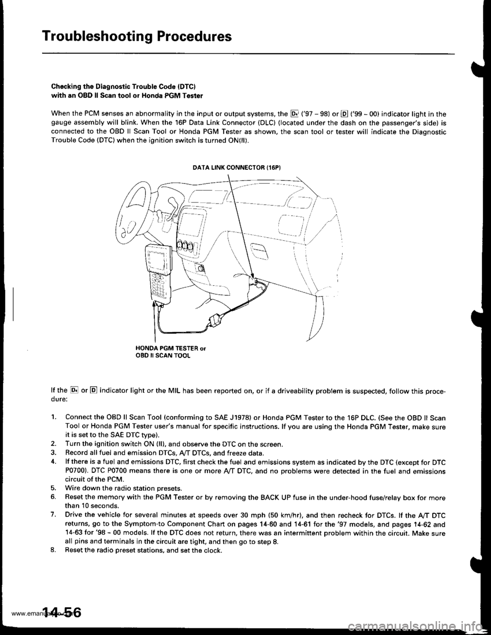
When the PCM senses an abnormality in the input or output systems, the El ('97 - 98) or E ('99 - O0) indicator light in thegauge ass€mbly will blink. When the 16P Data Link Connector (DLC) {located under the dash on the passenger's side) is
connected to the OBD ll Scan Tool or Honda PGM Tester as shown, the scan tool or tester will indicate the Diagnostic
Trouble Code (DTC) when the ignition switch is turned ON(ll).
HONDA PGM TESTER olOBD II SCAN TOOL
lf the E or E indicator light or the MIL has been reported on, or if a driveability problem is suspected, follow this proce-
dure:
1. Connect the OBD ll Scan Tool (conforming to SAE J1978) or Honda PGM Tester to the 16P DLC. (See the OBD ll ScanTool or Honda PGM Tester user's manual for specific instructions. lf you are using the Honda PGM Tester, make sureit is set to the SAE DTC Wpe).2. Turn the ignition switch ON (ll), and observe the DTC on the screen
3. Record allfuel and emission DTCS, A,,/T DTCS, and freeze data.
4. lf there is a fuel and emissions DTC, first check the fuel and emissions system as indicated by the DTC (except for DTCP0700). DTC P0700 means there is one or more Ay'T DTC, and no Droblems were detected in the fuel and emissionscircuit of the PCM.
5. Wire down the radio station presets.
6. Reset the memory with the PGM Tester o. by removing the BACK UP fuse in the under-hood fuse/relay box for morethan 10 seconds.
7. Drive the vehicle for several minutes at speeds over 30 mph (50 km/hr), and then recheck for DTCS. lf the A/T DTCreturns, 9o to the Symptom-to Component Chart on pages 14-60 and 14-61 for the '97 models, and pages 14-62 and14-63 for '98 - 00 models. lf the OTC does not return, there was an intermittent problem within the circuit. Make sureall pins and terminals in the circuit are tight, and then go to step 8.8. Reset the radio Dreset stations, and set the clock.
DATA LINK CONNECTOR {16PI
[ -=.r,
ili,i /i,
v,., i
14-56
www.emanualpro.com
Page 1141 of 1395

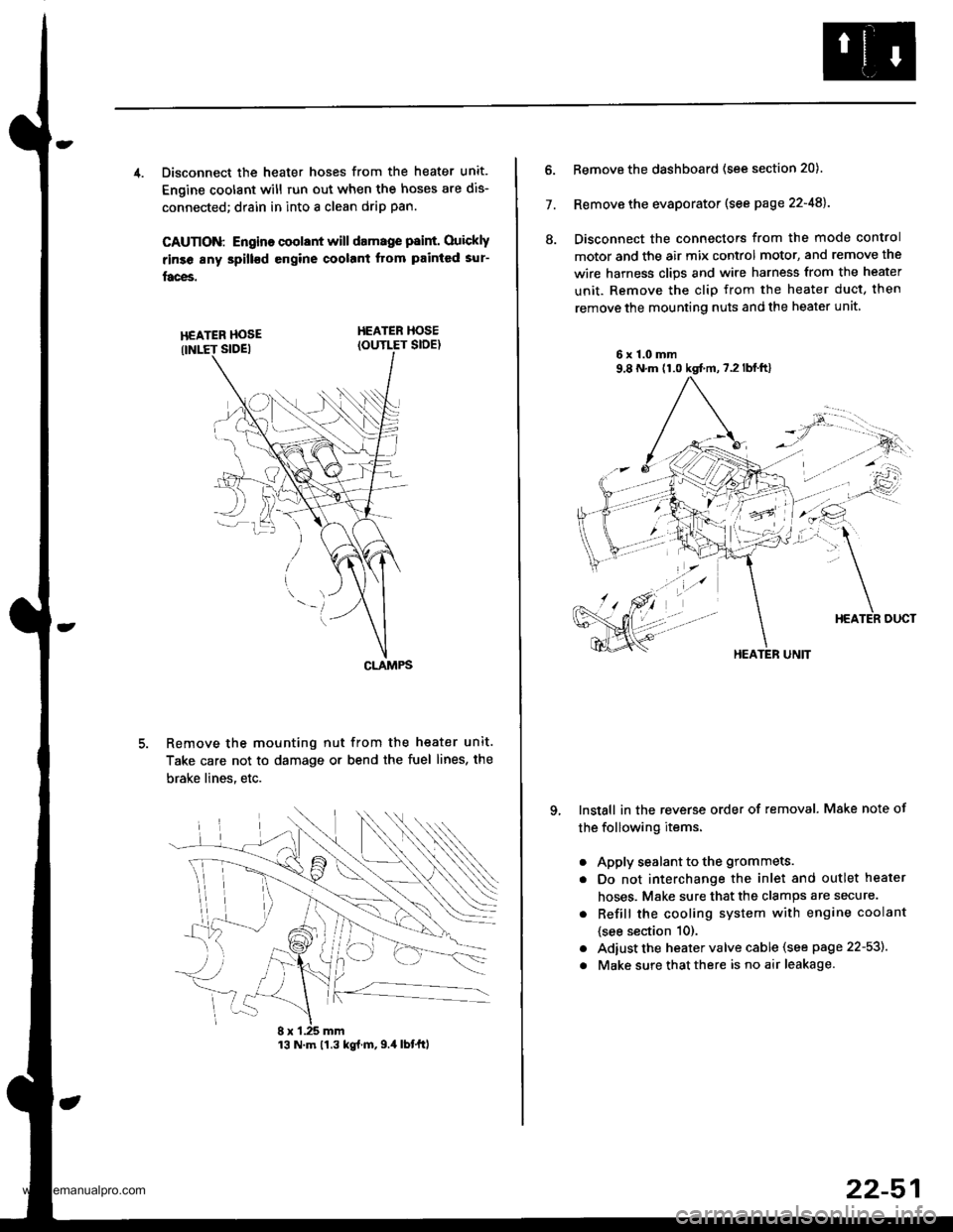
4. Disconnect the heater hoses from the heater unit.
Engine coolant will run out when the hoses are dis-
connected; drain in into a clean drip pan.
CAUTION: Engino coolant will damage p8int. Ouickly
rinse any spill€d engine coolant Itom painted sur-
faces.
HEATER HOSEIOUTLET SIDE)
Remove the mounting nut from the heater unit.
Take care not to damage or bend the fuel lines, the
brake lines. etc.
CLAMPS
13 N.m 11.3 kg{.m,9.4 lbtftl
22-51
7.
ll.
Remove the dashboard (see section 20).
Remove the evaporator (see page 22-48).
Disconnect the connectors from the mode control
motor and the air mix control motor, and remove the
wire harness clips and wire harness from the heater
unit. Remove the clip from the heater duct, then
remove the mounting nuts and the heater unit
6x1.0mm9,8 N.m (1.0 kgt m,7.2lblft)
qInstall in the reverse order of removal. Make note of
the following items.
a
a
a
a
Apply sealant to the grommets.
Do not interchange the inlet and outlet heater
hoses. Make sure that the clamps are secure.
Refill the cooling system with engine coolant
{see section 10).
Adiust the heater valve cable (see page 22-53).
Make sure that there is no air leakage.
HEATER UNIT
www.emanualpro.com
Page 1161 of 1395

Body Electrical
Speciaf Toofs ,...,..,.............-.23-2
Troubleshooting
Tips and Precautions ......,.,..........,.................. 23-3
Five-step Troubleshooting ........,.,.,...,,.,......... 23-5
Wire Color Codes ...,....,.. 23-5
Relay and Control Unit Locations
Engine Compartment ..,.,......,......................... 23-6
Dashboard ,.,.,..............-.- 23-7
Door ....................... .........23-10
Index to Cilcuits and Sysiems
Accessory Socket .. ,....,.,..,.,. 23-95*Airbags ................ .,....,. Sestion 24
Air Conditioning ,.,.,.... Section 22
Alternator ................... Section 4
Anti-lock Brake System {ABSI ................... Section 19'A/T Gear Position Indicator ....................... Section 1,1
Automatic Transmission System ...........,.. Section 14
Battery ................... ..............23-50
Blower Controls .,...,.,, Section 22
Charging System ....... Seqtion il
Clock -'98 Model ................ 23-98
Connector ldentification and Wire HarnessRouting .................. ......... 23.11
Cruise Control ............ Ssction 4
Dash Lights Brightness Contlo||er ..................... 23-90
Fan Conlrols ...,......,.... Section 10
Fuel Pump ,..,.,...,....,.... Section 11
Fuses...................... .,,.,.,.,.,,.,23-40*Gauges
Circuit Diagram ......-....-..23-58
Fuel Gauge .....,.,..... Section 11
Speedometer ..,..........,... 23-56
Ground Distribution ,....,.,...23-46
Hatch Glsss ODenor .........................,.,.,.,.,..,.,.,.,,. 23-121
Heater Controls .-........ Soction 21*Horns.,...,..,.,.,....... ................23"104*fgnition Switch ,,.,.,..,.,.,,.,.,.,23-51
lgnition Key Light System -'97 Mod6l .............. 23.88
-+
BODY
www.emanualpro.com
Page 1186 of 1395

Connector ldentification and Wire Harness Routing
Left Side Wire Harness
Connector oI
Terminal
Number of
CavitiesLocaiionConnects toNot6s
c551
c552
c554
c556
c558
c559
c559
c560
c562
c563
c563
c564
c565
c566
c568
c569
c570
c572
c573
c57 4
c575
c576
c578
c579
c580
c581
8
16
10
14'I
14
16
20
20
24
)
1
5
1
1
6
1
2
14
1
1
6
1
6
Behind under-dash fuse/relay box
Behind under-dash fuse/relay box
Left side of steering wheel
Left side of steering wheel
Left side of steering wheel
Above under-dash fuse/relay box
Above under-dash fuse/relay box
Driver's door
Behind left kick panel
Behind left kick panel
Behind left kick panel
Left side offloor
Left quaner panel
Fueltank
On left half of rear cross beam
On left half of rear cross beam
Left quarter panel
Left quarter panel
Left quarter panel
Left quarter panel
Left quarter panel
Left quarter panel
On left half of rear cross beam
Right quarter panel
Right quarter panel
Left quarter pillar
Left side of floor
Left B-piller
Left B-piller
Behind left kick panel
Behind left kick panel
Under left side of dash
Left B-piller
Fueltank
Left side of steering wheel
Under-dash fuse/relay box (C921)
Under-dash fuse/relay box (C923)
Power mirror switch
Power window master switch
Power window master switch
Dashboard wire harness {C505)
Dashboard wire harness 1C505)
Driver's door wire harness (C661)
Main wire harness (C403)
Main wire harness (C404)
Main wire harness (C404)
Driver's seat belt switch
Left rear door switch
Fuel unit
Left rear ABS wheel sensor
Left rear ABS wheel sensor
Rear accessory socket connector {+}
Rear accessory socket connector (-)
Rear bumper wire harness 1C641)
Trailer lighting connector
Tailgate door latch switch
Left rear speaker
Right rear ABS wheel sensor
Rear wire harness (C611)
Right rea. door switch
Left taillight
Parking brake switch
Left rear door wire harness (C681)
Driver's door switch
Select unlock relay (for security alarm
system)
Junction connector (for power door
locks)
SRS main harness (C807)
Driver's seat belt tensioner
Fuel tank pressure sensor sub-harness(c645)
Power window master switch
'97 - 98
mooets'99 - 00
models
'97 model'98 - 00
models
Optional
'97 model'98 - 00
models
'98 - 00
mooets'98 - 00
models'98 - 00
mooets'99 - 00
mooets
G551
G553
Behind left kick panel
Left side ot floor
Left quarter piller
Body ground, via left side wire harness
Body ground, via left side wire harness
Body ground, via left side wire harness
23-26
www.emanualpro.com
Page 1217 of 1395

l-
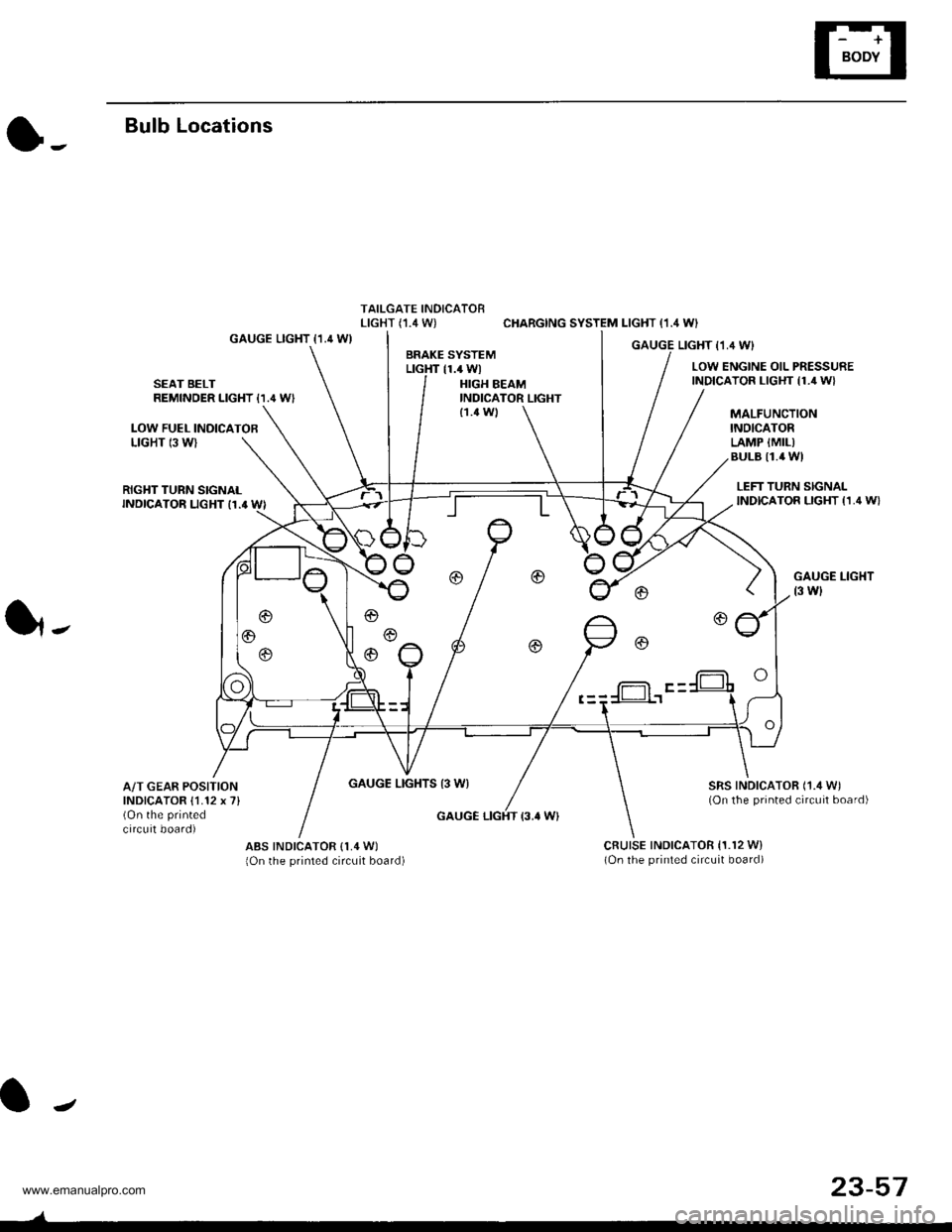
Bulb Locations
TAILGATE INDICATORLIGHT (,I.4 W) CHARGING SYSTEM LIGHT (1.4 WI
GAUGE LIGHT {1.4 WIGAUGE LIGHT I1,4 WIBRAKE SYSTEMLTGHT 11.4 WlLOW ENGINE OIL PRESSUREINDICATOR LIGHT {1./r W}SEAT BELTREMINDER LIGHT {1.' W'HIGH BEAMINDICATOR LIGHT
LOW FUEL INOICATOBLIGHT 13 WI
MALFUNCTIONINOICATORLAMP {MIL)BULB I1.4 WI
{1.4 Wl
RIGHT TURN SIGNALINDICATOR LIGHT I1.' WI
GAUGE LIGHTS 13 WI
LEFT TURN SIGNALINDICATOR LIGHT {1,4 W}
GAUGE LIGHT
t3 wl
SRS INDICATOR ('1./t W)(On the printed circuit board)
1,.
A/T GEAR POSITIONINDICATOR {1.12 x 7}(On the printed
circuit board)GAUGE LIGHT {3.' W}
ABS INDICATOR (1,4 W)
lOn the printed circuit board)cRutsE tNDtcAToR 11.r2 w)(On the printed circuit board)
f-= F -
J
23-57
www.emanualpro.com