Page 427 of 1395
Transaxle
Clutch ...........12-1
Manual Transmission ............................ 13-1
Automatic Transmission .................. ..... 1 4-1
Differential ... 15-1
Driveshafts ... 16-1
www.emanualpro.com
Page 429 of 1395
Special Tools
Rel. No. I Tool NumberDescriptionOty Page Reference
a
IA
@
!c,
Lo,
OTJAF - PM70,I1A
07NAF - PR30l00
07LAB - PV00100 or
07924 - PD20003
07746 0010100
07749 - 0010000
07936 - 3710100
Clutch Alignment Disc
Clutch Alignment Shaft
Ring Gear Holder
Attachment, 32 x 35 mm
Driver
Ha nd le
1 | t2-7
1 12-7 , A, '�t0, 11
1 12-7 ,9, 10, 1'l
I1 I 12-10
1 12-10
1 12-7 , a, 10, 11
b)
2-2
www.emanualpro.com
Page 437 of 1395
FlywheelClutch Disc, Pressure Plate
Replacement (cont'dl
Drive the new bearing
specialtools.
HANOLE DRIVER07749-
ATTACHMET{T-32x35mm07746 -O010100
FLYWHECI-
Align the hole in the flywheel with the crankshaft
dowel pin, and install the flywheel. Install the
mounting bolts finger-tight.
Install the special tool, then torque the flywheel
mounting bolts in a crisscross pattern in several
steps as shown.
Torque:12 x 1.0 mmr03 N.m (10.5 kgl.ln,75.9 tbtftl
into the flywheel using the
12-10
Installation
1. Install the ring gear holder.
CLUTCH ALIGNMENT SHAFT07NAF - PR30100
CLUTCH DISC
RING GEAR HOLDER07LAB _ pvoot(x) or07924 _ PD20003
Apply grease to the spline of the clutch disc, then
install the clutch disc using the special tools.
NOTE: Use only Super High Temp Urea Grease(P/N 08798 - 9002).
lnstall the pressure plate.
PRESSURE PLATE
www.emanualpro.com
Page 440 of 1395

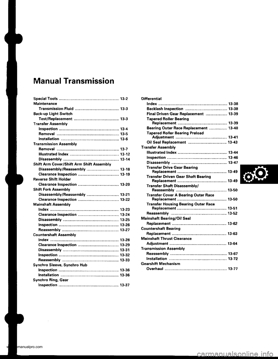
Manual Transmission
Diff€rential
lndex ...................... ......... 13-38
Backlash Inspestion ..,....,.,.....................,......, 13-38
Final Driven Gear Replacement .................... 13-39
Tapered Roller BearingReplacement ............. 13-39
Bearing Outer Race Replacement ......,.,........ 13-i10
Tapered Roller Bearing PreloadAdiustment ............... 13-il1
Oil Seal Reolacement .................................... 13-/l:}
Transfer Assembly
lllustrated Index ............. 13-il4
Inspection ..,....,.,......,...... 13-46
Disassembly ................... 13-47
Transfer Drive Gear BearingReplacement ...,..................,....................... 13-ilg
Transfer Driven Gear Shaft BearingReplacement .............................................. 13-ilg
Transfer Shaft Disassembly/Reassembly .............. 13-50
Transler Cover A Bearing Outer RaceRep1acement.........,.,.,..........,....,...,.........,., 13-50
Transter Housing Bearing Outer RaceReD1acement.............................................. 13-51
Reassembly ..-............,... 13-52
Mainshaft Bearing/Oil Seal
Beplacement .................. 13-62
Countershaft Bearing
Replacement .,,.,.,., ..,...... 13-63
Mainshaft Thrust Clearance
Adiustment .................... 13-6,1
Transmission Assembly
Reassembly .,.,.,.,..,.,....,., 13-67
fnstaffation .,.,.............,... 13-72
Gearshift Mechanism
Overhaul ................ .........13-17
www.emanualpro.com
Page 441 of 1395

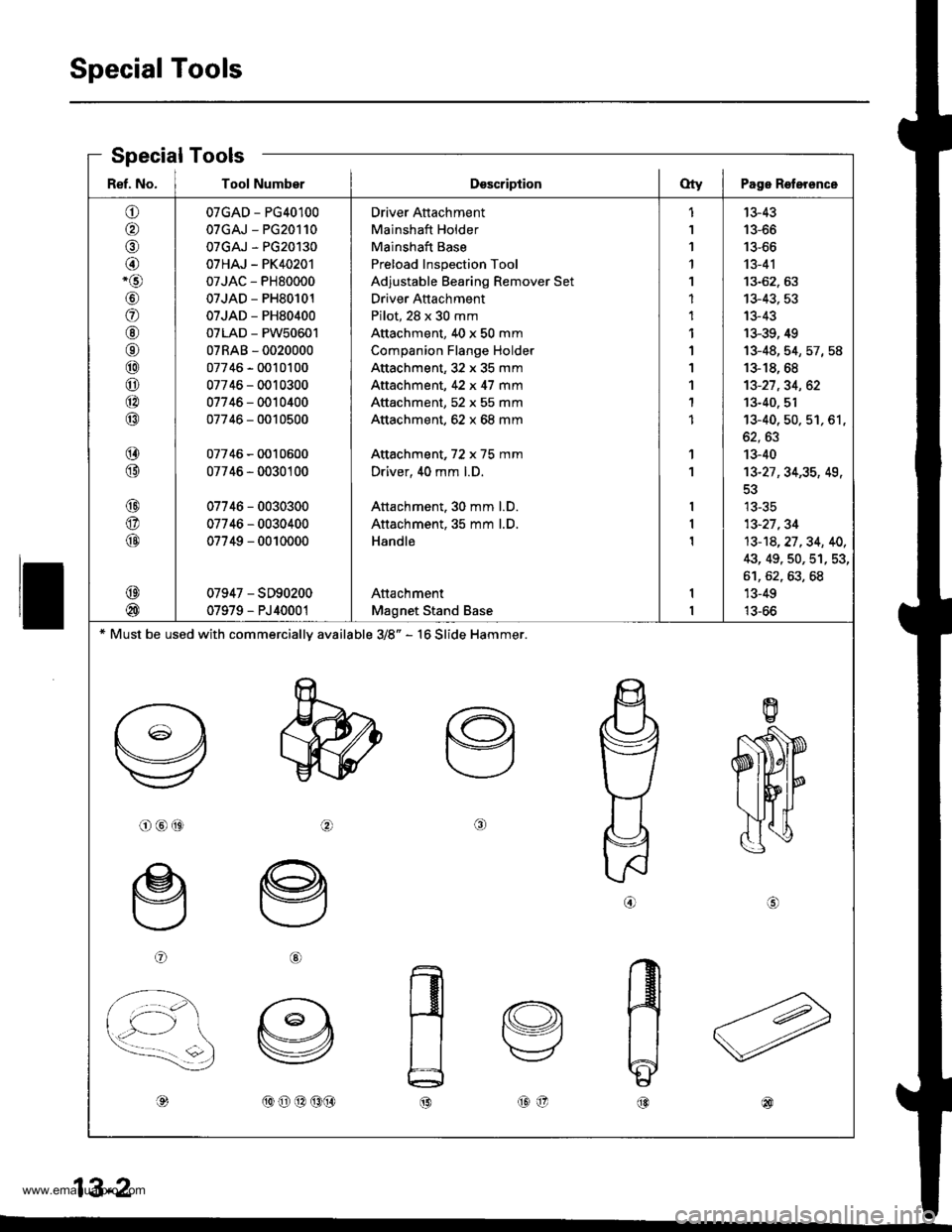
Special Tools
ll
Ref. No. I Tool NumberDsscriptionOty I Page Roterence
o
o,6)
@-o
\9'
a
@6r
@
o
@
@
@
@
@
@
@
@
@
07GAD - PG40100
07GAJ - PG20110
07GAJ - PG20130
07HAJ - PK40201
07JAC - PH80000
07JAD - PH80101
07JAD - PH80400
07LAD - PW50601
07RAB - 0020000
07746 - 0010100
07746 - 0010300
07746 - 0010400
07746 - 0010500
07746 - 0010600
07746 - 0030100
07746 - 0030300
07746 - 0030400
07749 - 0010000
07947 - SD90200
07979 - PJ40001
Driver Attachment
Mainshaft Holder
Mainshaft Base
Preload Inspection Tool
Adjustable Bearing Remover Set
Driver Attachment
Pilot, 28 x 30 mm
Attachment, 40 x 50 mm
Companion Flange Holder
Attachment,32 x 35 mm
Attachment, 42 x 47 mm
Attachment, 52 x 55 mm
Attachment, 62 x 68 mm
Attachment, 72 x 75 mm
Driver, 40 mm l.D.
Attachment. 30 mm l.D.
Attachment, 35 mm l.D.
Handle
Attachment
Magnet Stand Base
1
1
1'l
1
1
1
1
1
1'I
1
1
1
1
13-43
13-66
13-66
13-41
13-62. 63
13-43, 53
13-43
13-39, 49
13-48,54,57,58
13-18, 68
13-27,34, 62
13-40. 51't3-40, 50. 51, 61,
oz, oJ
13-40
13-27 ,34,35, 49,
tJ-5C
13-27,34
13-14,27.34, 40,
43, 49, 50, 51, 53,
61,62,63,68'13-49
13-66
* Must be used with commercially available 3/8" - 16 Slide Hammer.
o@(9ta\
oG)
,d,(oo@(9(}@o@
.A IAa 5-z
Special Tools
www.emanualpro.com
Page 448 of 1395
12. Disconnect the heated oxygen sensor (HO2S) con-
nector, then remove the exhaust pipe A.
GASKETReplace.
HO2S CONNECTOR
NUTReplace.
EXHAUST
SELF.LOCKINGReplace.
GASKETReplace.
Mark reference marks on the joint of the transfer
and the propeller shaft.
8 x 1.25 mmReplace.
Separate the propeller shaft from the transfer
assemDly.
REFERENCE MABKS
14.
15. Remove the cotter pins, and castle nuts. then sepa-
rate the ball ioints from the lower arm (see sectlon
18).
OAMPER PINCH BOLT
CASTLE NUTNUTReplace.
17.
16.
DAMPER FORKFOFKEOLTReplace.
Remove the right damper tork bolt, then separate
right damper fork and damPer.
Pry the right driveshaft out of the differential, and
pry the left driveshaft out of the intermediate shaft
(see section 18).
Pull out the inboard ioint, and remove the right and
left driveshaft (see section 18).
Tie plastic bags over the driveshatt ends. Coat all
precision finished surfaces with clean engine oil
18.
19.
\
{cont'd}
13-9
www.emanualpro.com
Page 466 of 1395
Reassembly
NOTE: Refer to page 13-23 for reassembly sequence.
1. Suppon 2nd gear on steel blocks as shown, then
install the 3rd/4th synchro hub using the special
tools and a press as shown.
NOTE: After installing, inspect the operation of the
3rd/ 4th synchro hub set.
PRESS
I
3RD/4THSYNCHRO HUB
DRIVER, ,l(} mm l.O.
07746 - 0030'�1 00
2.
2NO GEAR
Install the sth synchro hub using the special tools
and a press.
PRESS
I
DRlvER,40 mm l.D.
077{6 - 00301(x)
ATTACHMENT,35 mm l.D.077i16 - lx)3ollx)
sTH SYNCHBO HUB
3. Install the angular ball bearing using the special
tools and a oress. Note the direction of installation.
PRESS
I
077a6 - 0011x100
HANDLE07749 - 0010000
ATTACHMENT,/Vl x a7 mm
BALL BEARINGNote the dirediono{ installation.
13-27
www.emanualpro.com
Page 474 of 1395
8. Install sth gear using the special tools and a press.
PRESS
I
DRIVER, 40 mm l.D.
07715 - 0030300
ATTACHMENT,30 mm LD.077,16 - 0030300
LInstall the needle bearing using the special tools
and a press, then installthe bearing outer race
PRESS
I
DRIVER. 40 mm l.D.077{6 - 0030100
ATTACHMENT,30 mm l.D.07746 - 0030300
NEEDLEBEASING
10. Install the ball bearing using the special tools and a
press.
PRESS
I
DRIVER. 40 mm LD.07746 - 0030100
ATTACHMENT,30 mm LD.077a6 - 0030300
11.Securely clamp the countershaft assembly in
bench vise with wood blocks.
LOCKNUTReplace.
Install the spring washer.
Install the new locknut to the correct torque, then
stake the locknut tab into the groove.
Torque: 127 + 0 + 127 N.m 113 - 0 +13 kgf.m,
94+0-94|bf.ft)
12.
wooD slocKs
13-35
www.emanualpro.com