Page 684 of 1395
Transfer Assembly
Installation (cont'dl
Install the exhaust pipe A.
Connect the primary heated oxygen sensor (Primary
H02S) connector,
GASKETReplace.EXHAUST PIPE A
SELF.LOCKING NUT10 x 1.25 mm54 N.m {5.5 kgf.m,40 rbf.ft)Replace.
NUT8 x 1.25 mm16Nm11.6kgf.m,12 lbf.fOReplace.
-LOCKING
SELF-LOCKING NUT8 x 1.25 mm22 N.m (2.2 kgl.m,16 rbr.fttReplace.
10. Installthe splash shield and the guard bar.
6x1.0mm9.8 N.m {1.0 kgt.m,7.2 tbt.ftt
14-168
'I '�I.
12.
Refillthe transmission with ATF (see page 14-161).
Start the engine, and run it to normal operating tem-perature (the radiator fan comes on), Turn theengine off and check ATF level.
www.emanualpro.com
Page 712 of 1395
Main Valve Body
Disassembly/lnspection/Reassembly
NOTE:
. Do not use a magnet to remove the check balls; it may magnetize the balls.t clean all parts thoroughly in solvent or carburetor cleaner, and dry them with compressed ai.. Blow out all passages.. Replace the valve body as an assembly if any parts are worn or damageo.. Checkall valvesforfree movement. lfanyfailtoslidefreely,seeValveBodyRepaironpage.t4_192.. Coat all parts with ATF during reassembly.
VALVE CAP CLIP
2ND ORIFICE CONTROL VALVE
SPRING SEAT
BALLS, 8
ACCUMULATOR CHOKE
VAI-VE
FELI€F VALVE
@
UK
MAIN VALVE BOOYInspect for wear, scratches,and sconng.
sERVO CONInOL
:,/\^._.^,
I-2 SHIFT VALVE
14-196
www.emanualpro.com
Page 761 of 1395

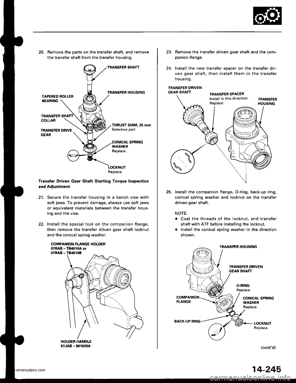
20. Remove the parts on the transfer shaft, and remove
the transfer shaft from the transfer housinq.
TRANSFER SHAFT
TRANSFER HOUSINGTAPEFED ROLLERBEARNG
TRANSFERCOLLAR
TRANSFER DRIVEGEAR
THRUST SHIM, 25 mmSelective pan
CONICAL SPRINGWASHERReplace.
Transf€r Driven Gear Shaft Starting Torque Inspsction
and Adjustment
21. Secure the transfer housing in a bench vise with
soft jaws, To prevent damage, always use soft jaws
or equivalent materials between the transfer hous-
ing and the vise.
22. Install the special tool on the companion flange,
then remove the transfer driven oear shaft locknut
and the conical spring washer.
COMPANION FLANGE HOLDER07RAB - TB,010A ol07RAB - TB,010B
Replace.
23. Remove the transter driven gear shaft and the com-
panion flange,
24. Install the new transfer spacer on the transfer dri-
ven gear shaft, then install them in the transfer
housrng.
TRANSFER DRIVENGEAR SHAFTTFANSFER SPACERlnstall in this direction.Replace.
25.Install the companion flange, O-ring, back-up ring.
conical spring washer and locknut on the transfer
driven gear shaft.
NOTE:
. Coat the threads of the locknut, and transfer
shaft with ATF before installing the locknut.
. Install the conical spring washer in the direction
shown,
TRANSFER HOUSING
O.RINGReplace.
CONICAL SPRINGWASHERReplace.
LOCKNUTReplace.
(cont'd)
BACK.UP RING
14-245
www.emanualpro.com
Page 779 of 1395

26. Connect the vehicle speed sensor (VSS). the coun-
tershaft speed sensor. and the A,/T gear position
switch connectors,
VEHICLE SPEEO
SPEED SENSOACO'{NECTOR
Connect the lock-up control solenoid valve connec-
tor, then install the harness clamp on the clamp
bracket.
HARNESS CI-AMP
27.
RADIATOR HOSECLAMP
TRANSMISSIONGROUND CAB1ITERMINAL
LOCK-UP OONTROLSOLENOID VALVECONNECTOR
6x1.0mm12 N'm (1.2 kgi.m,8.? tbtftl
28.
29.
Instail the transmission ground cable terminal on
the transmission hanger, and install the radiator
hose clamp on the transmission hanger,
Connect the starter cables to the starter, and install
the harness clamD on the clamD bracket. Make sure
the crimped side of the starter cable ring terminal is
facing out.
STARTEBCABLE
STARTER CAAtf,
Install the air cleaner housing assembly and the
intake air duct.
Refill the transmission with ATF (see page 14-161).
Connect the battery positive terminal and negative
terminal.
Set the parking brake, Start the engine, and shift the
transmission through all gears three times.
Check the shift cable adjustment (see page 14-271]-.
Check the tront wheel alignment and adjust it if
needed (see section 18).
Let the engine reach normal operating temperature
(the radiator fan comes on) with the transmission in
E or N position, then turn it off and check the ATF
level {see page 14-160).
Perform a road test (see page 14-157 and 14-158).
30.
31.
34.
CLAMP BRACKET
37.
14-263
www.emanualpro.com
Page 800 of 1395

Real-time 4WD-Dual Pump System
Troubleshooting (Automatic Transmissionl
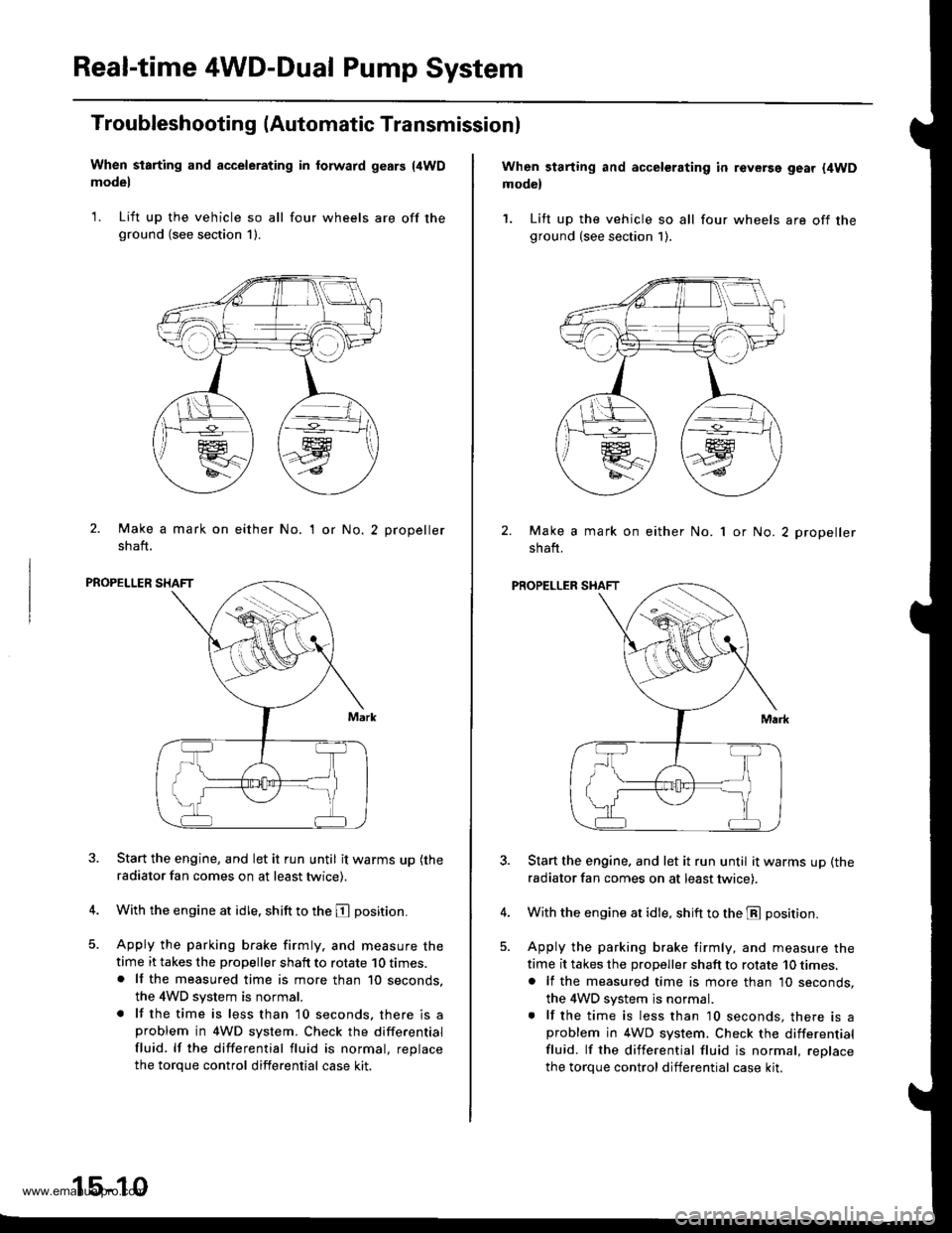
When starting and accelerating in forward gesrs {4WDmodel
1. Lift up the vehicle so all four wheels are off theground (see section 1).
2. Make a mark on either No.
shaft.
'I or No.2 propeller
PROPELLER SHAFT
Start the engine, and let it run until it warms up (the
radiator fan comes on at least twice).
With the engine at idle. shift to the E position.
Apply the parking brake firmly. and measure thetime it takes the propeller shaft to rotate 10 times.. lf the measured time is more than 10 seconds,
the 4WD system is normal.
. lf the time is less than 10 seconds, there is aproblem in 4WD system. Check the differential
fluid. lf the differential fluid is normal, replace
the torque control differential case kit.
15-10
When starting and accelerating in revGrsg gear {4WDmodel
1. Lift up the vehicle so all four wheels are off theground (see section 1).
Make a mark on either No.
shaft.
1 or No. 2 propeller
PROPELLER SHAFT
Start the engine. and let it run until it warms up (the
radiator fan comes on at least twicei.
With the engine at idle, shift to the E position.
Apply the parking brake firmly, and measure the
time it takes the proDeller shaft to rotate 10 times,. lf the measured time is more than 10 seconds,
the 4WD system js normal.. lf the time is less than 10 seconds, there is aproblem in 4WD system. Check the differential
fluid. lf the differential fluid is normal, reolace
the torque control differential case kit.
www.emanualpro.com
Page 801 of 1395

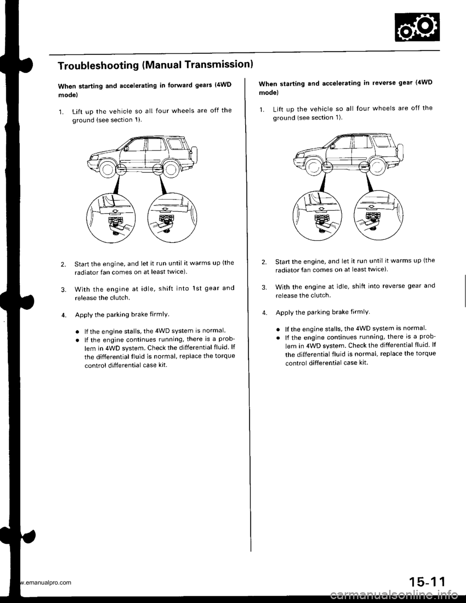
Troubleshooting (Manual Transmissionl
When starting and accelerating in forward gears (4WD
mode)
1. Lift up the vehicle so all four wheels are off the
ground {see section 1)
3.
Start the engine, and let it run until it warms up (the
radiator fan comes on at least twlce).
With the engine at idle, shift into 1st gear and
release the clutch.
Apply the parking brake firmlY
. lf the engine stalls, the 4WD system is normal.
. lf the engine continues running, there is a prob-
lem in 4WD system. Check the differential fluid. lf
the differential fluid is normal, replace the torque
control ditferential case kit.
2.
When starting and accelerating in reverse gear (4WD
model
1. Lift up the vehicle so all four wheels are off the
ground (see section 1).
Start the engine, and let it run until it warms up (the
radiator fan comes on at least twice)
With the engine at idle, shift into reverse gear and
release the clutch.
Apply the parking brake firmlY
. lf the engine stalls, the 4WD system is normal.
. lf the engine continues running, there is a prob-
lem in 4WD system. Check the differential fluid lf
the differential fluid is normal, replace the torque
control differential case kit.
3.
www.emanualpro.com
Page 1095 of 1395
SLOWER MOTOR RELAY,RADIATOR FAN RELAY.CONDENSER FAN REI-AY,COMPRESSOR CLUTCH RELAY(Located in the undeFhood fuse/relay box)Test. page 22-45
CONDENSER FAN 2P CONNECTOB
RADIATOR FAN2P CONNECTORA/C PRESSURE SWITCH2P CONNECTOR
COMPARTMENTWIRE HARNESS
{cont'd)
1P CONNECTOR
22-5
www.emanualpro.com
Page 1100 of 1395

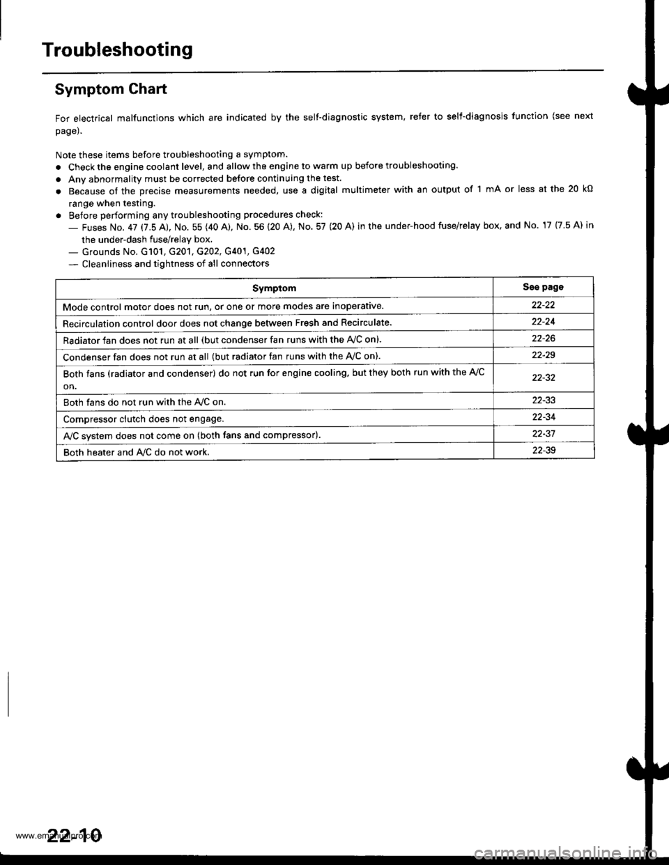
Troubleshooting
Symptom Ghart
For electrical malfunctions which are indicated by the self-diagnostic system, reter to selt-diagnosjs function (see next
page).
Note these items before troubleshooting a symptom.
. Check the engine coolant level, and allow the engine to warm up before troubleshooting.
. Anv abnormality must be corrected before continuing the test.
. Because of the precise measurements needed, use a digital multimeter with an output of 1 mA or less at the 20 kO
range when testing.
. Before performing any troubleshooting procedures check:
- Fuses No. 47 17.5 AJ, No. 55 (40 A), No. 56 (20 A), No. 57 (20 A) in the under-hood fuse/relay box, and No. 17 {7.5 A) in
the under-dash fuse/relay box.._ Grounds No. G101, G201, G202, G401, G4O2
- Cleanliness and tightness of all connectors
SymptomSse pags
Mode control motor does not run, or one or more modes are inoperative.
Recirculation control door does not change between Fresh and Recirculate.22-24
Radiator fan does not run at all (but condenser fan runs with the AVC on).
Condenser fan does not run at all {but radiator fan runs with the Ay'C on).22-29
Both fans (radiator and condenser) do not run for engine cooling. but they both run with the A,/C
on.
Both fans do not run with the Ay'C on22-33
Compressor clutch does not engage.22-34
AJC svstem does not come on (both fans and compressor).22-37
Both heater and A/C do not work,22-39
22-10
www.emanualpro.com