Page 391 of 1395
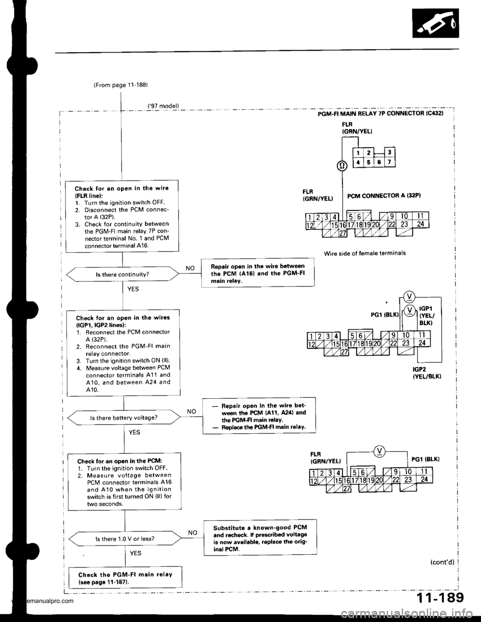
lFrom page 11 188)
Ch6ck lor an open in the wir€
{FLR line):1. Turn the ignition switch OFF.
2. Disconnect the PCM connec-
tor A (32P).
3. Check for continuity between
the PGM-FI main relay 7P con-
nector terminal No. 1 and PCM
connector terminal A16.
Repair open in the wire be{weonthe PCM lAl6l and the PGM-FImain relay.
Check for an open in the wir€s
{lGP1, lGP2lin€s):'1. Reconnect the PCM connectorA (32P).
2. Reconnect the PGM'Fl main
relay connector.3. Turn the ignition switch ON (lli.
4. Measure voltage between PCM
connector terminals A11 and
A10, and between A24 andA10.
- Repair open in the wir€ bet'
ween th€ PCM {A11, A2ia} end
the PGM-FI main relay.- Reolsce the PGM-FI main rolaY.
ls there battery voltage?
Check tor an open in the PCM:
1. Turn the ignition switch OFF.2, Measu re voltage betweenPCM connector terminals A16
and A10 when the ignition
switch is first turned ON {ll) for
Substitute a known-good PCM
and recheck. lf ptesctibed volttgeis now available, roplaco tho orig'in.lPCM.
ls there '1.0 V or less?
Check the PGM-Fl m.in.elaV(see page 11-187).
('97 model)
IGRN/YELI
-t
PGM.FI MAIN RELAY 7P CONNECTOR (C432I
FLR
Wire side of lemale terminals
IGP2(YEL/BLK)
(cont'd)
_l
1 1-1 89
www.emanualpro.com
Page 392 of 1395
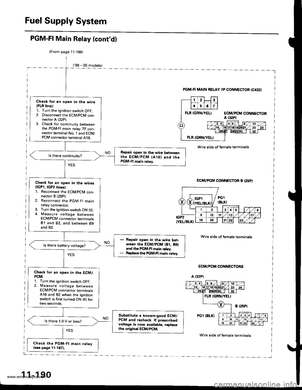
Fuel Supply System
PGM-FI Main Relay (cont'dl
('98 - 00 models)-l
(From page 11,188)
Check lor an open in the wire(FLR line):1. Turn the ignition switch OFF.2. Disconnect the ECM/PCM connector A (32P1.3. Check for continuity betweenthe PGM-FI main relay 7P con-nector terminal No. '1 and ECM/PCM connector terminal 416.
Repaia open in the wire betweenthe EcM/PcM lAl5l .nd thePGM-FI m.in relay.
Check for an open in the wiresllcPl,lGP2linos):1. Reconnect the ECM/PCN4 con-nector I (25P).2. Reconnect the PGM Fl mainretay connector.3. Turn the ignition switch ON l).4, Measure voltage betweenECM/PCM connector terminalsB1 and 82, and between 89and 82.
Ropai. open in tho wire b6t-we€n th. ECM/PCM lBt, Btl.nd the FGM-FI main rd.y.R€plac€ th6 FGM+| main retay,
Chock for an open in the ECM/PCM:1. Turn the ignition switch OFF.2, Measure voltage betweenECM/PCM connector terminals416 and 82 when the ignitionswitch is first turned ON (tl) for
Subrtitute e known-good ECM/PCM and recheck. lf prescribsdvoltage b now ovrihble, replacothe originel ECM/PCM.
ls there 1.0 V or less?
Check the PGM-FI main.elav(s6e page 11-1871.
PGM.FI MAIN RELAY 7P CONNECTOF (C€2)
Wire sid€ of female terminals
ECM/PCM CONNECTOR B I25PI
IGP2(YEL/BLKI
ECM/PCM CONNECTORS
a t32Pl
Wire side of female terminals
Wire side of f€male terminsls
1 1-190
Dde"Jt;;liL-F-T--
PGl(BLK}
38s l1011131719202122
www.emanualpro.com
Page 577 of 1395
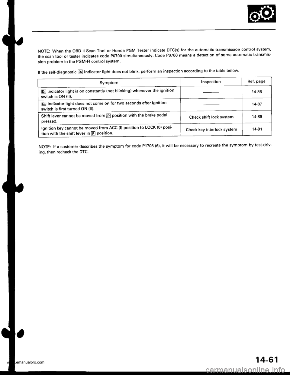
NOTE: When the OBD ll Scan Tool or Honda PGM Tester indicate DTC(s) for the automatic transmission control system'
the scan tool or tester indicates code P0700 simultaneously. code P07oo means a detection of some automatic transmis-
sion problem in the PGM-Fl control system
lf the self-diagnostic E indicator light does not blink, perform an inspection according to the table below.
NOTE: lf a customer describes the symptom for code P1706 (6), it will be necessary to recreate the symptom by test-driv-
ing, then recheck the OTC.
SymptomInspectionRef. page
E indicator light is on constantly (not blinking) whenever the ignition
switch is ON (ll).14-86
E indicator light does not come on for two seconds after ignition
switch is first turned ON (ll).
't 4-41
Shift lever cannot be moved from @ position with the brake pedal
Dressed,Check shift lock system14-89
lgnition key cannot be moved from ACC (l) position to LOCK {0) posi
tion with the shift lever in E position.Check keY interlock system14-91
14-61
www.emanualpro.com
Page 579 of 1395
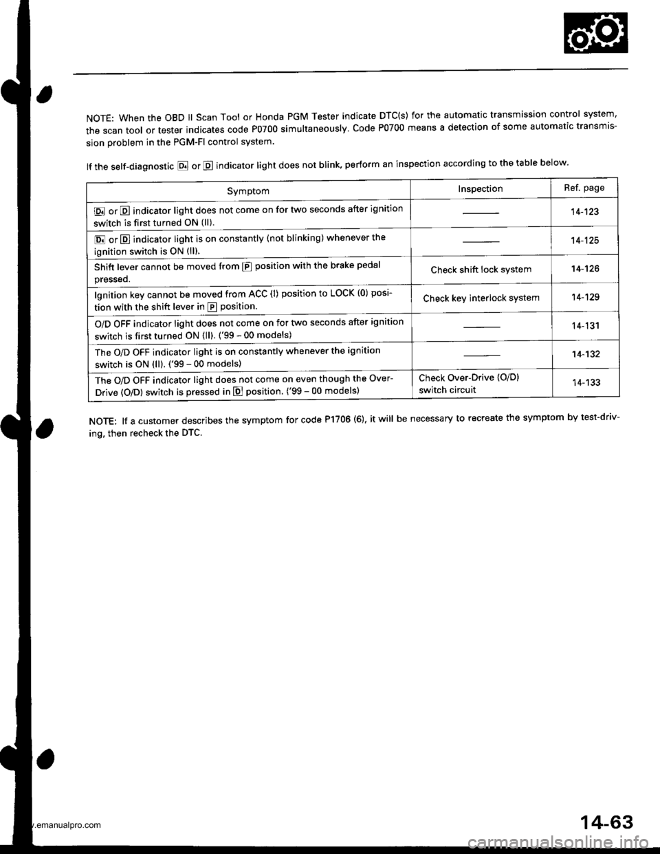
NOTE: When the OBD ll Scan Tool or Honda PGM Tester indicate DTC(S) for the automatic transmission control system,
the scan tool or tester indicates code P0700 simultaneously. Code P0700 means a detection of some automatic transmis-
sion problem in the PGM-Fl control system.
lf the self-diagnostic E or E indicator light does not blink, perform an inspection according to the table below.
NOTE: lf a customer describes the symptom for code P17OO (6), it will be necessary to recreate the symptom by test-driv-
ing. then recheck the DTC.
SymptomInspectionRef. page
E or E indicator light does not come on for two seconds after ignition
switch is first turned ON (ll).14-123
E or E] indicator light is on constantly (not blinking) whenever the
ignition switch is oN {ll).
14-125
Shift lever cannot be moved from E position with the brake pedal
presseo.Check shift lock system14-'t26
lgnition key cannot be moved from ACC (l) position to LOCK (0) posi-
tion with the shift lever in E position.Check key interlock system14-129
O/D OFF indicator light does not come on for two seconds after ignition
switch is first turned ON (ll). ('99 - 00 models)14-131
The O/D OFF indicator light is on constantly whenever the ignition
switch is ON (ll). ('99 - 00 models)14-132
The O/D OFF indicator light does not come on even though the Over-
Drive (O/Dl switch is pressed in E position. ('99 - 00 models)
Check Over-Drive {O/D}
switch circuit14-133
14-63
www.emanualpro.com
Page 604 of 1395
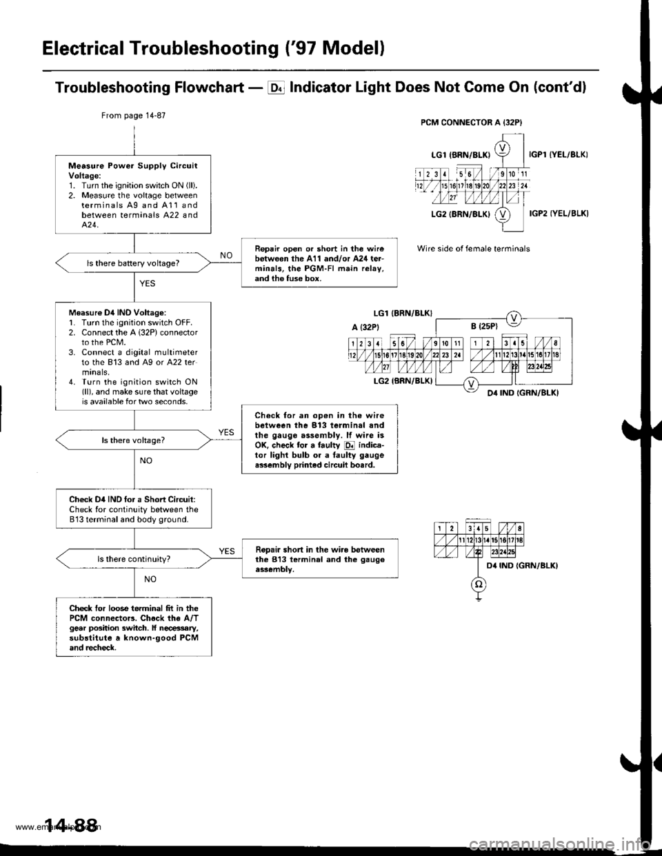
Electrical Troubleshooting ('97 Modell
Troubleshooting Flowchart - E Indicator Light Does Not Gome On (cont'dl
IYEL/BLK)
IGP2 IYEL/BLK)
Wire side of female terminals
From page 14-87
Measure Power Supply circuitVoltage:1. Turn the ignition swatch ON (ll).
2. Measure the voltage betweenterminals Ag and A11andbetween terminals A22 andA�24.
Repair open or short in the wirebotw€on the A11 and/or A24 ter-minals, the PGM-FI main relav,and ih6 fuse box.
ls there baRery voltageT
Measur€ Dil INO Voltag6:L Turn lhe ignition switch OFF.2. Connect the A 132P) connectorto the PCM.3. Connect a digital multimeterto the 813 and A9 or A22 termtnals,4. Turn the ignition switch ON(ll), and make sure that voltageis available for two seconds.
Check for an op€n in the wirebetween the 913 terminal andthe gauge assembly. lf wire isOK. check tor a faulty E indica-tor lighl bulb or a taulty gaugea$embly printed circuil bo.rd.
Check D4IND tor a Short Circuit:Check for continuity between the813 terminal and body ground.
Ropair short in the wiro betweenthe 813 lerminal and the gaugeassembly.
Check tor loose terminal frt in thePCM connector3. Chock the A/Tgear position switch. ll necessary,substitute a known-good PCMand recheck.
14-88
www.emanualpro.com
Page 639 of 1395
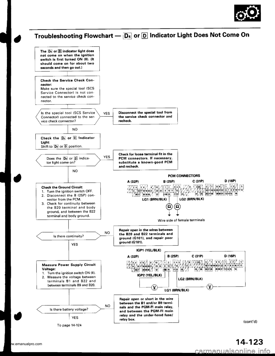
Troubleshooting Flowchart - Df or @ Indicator Light Does Not Come On
PCM CONNECTORS
B t2sPl c (31D (16P)
l*f4tr 8-
f - -- -6 3 rol ,: irr t lrpri$fe?0?r/a)1 e 'oI 13 11/ / l//|rrr I , ltelx ?r2? r,/i-T_LG1 {8RN/BI-KI I LG2 (BRN/BL()I
@@I++
Wire side of lemale terminals
(cont'd)
14-123
The E or El indicator light doe3not cofie on when the ignitaon
switch is first turned ON {ll). {ltshould como on for about two
s.cond3 and ihen go out.l
Check ths Service Check Con-
neclor:Make sure the special tool (SCS
Service Connector) is not connected to the service check connector.
Disconnecl the special lool lromtha service check connoctor andrecheck.
ls the special tool (SCS ServiceConnector) connected to the ser_vice check connector?
check the E or E Indicator
Ught:Shift to E or E position.
Check for loo3e t6lminal tit in thePCM connectors. lf necessary.substitute a known-good PCMand recheck.
Does the E or P indica-tor light come on?
Check the Gtound Circuil:1. Turn the ignition switch OFF.2. Disconnect the B (25P) con-nector from the PCM.3. Check for continuitY betweenthe 820 terminal and bodyground, and between the 822
terminal and body ground.
Repair open in the wires betweenthe 820 and 822 terminals andground {G1011, and r€Pair Poorground (G101).
ls there continuity?
Measure Power Supply CircuitVoltage:1. Turn the ignition switch ON 1ll).2. Measure the voltage betweenterminals B1 and 822 andbetween terminals Bg and 820.
Repair open or short in tho wi.ebetween the 81 and/or Bg tormi-nals and the PGM-FI main r€lay,.nd between tho PGM-FI mainrelay and the under-hood tuse/relay box.
ls there battery voltage?
A l32Plc (31P)
c (31P)
YES
To page 14-124
www.emanualpro.com
Page 642 of 1395
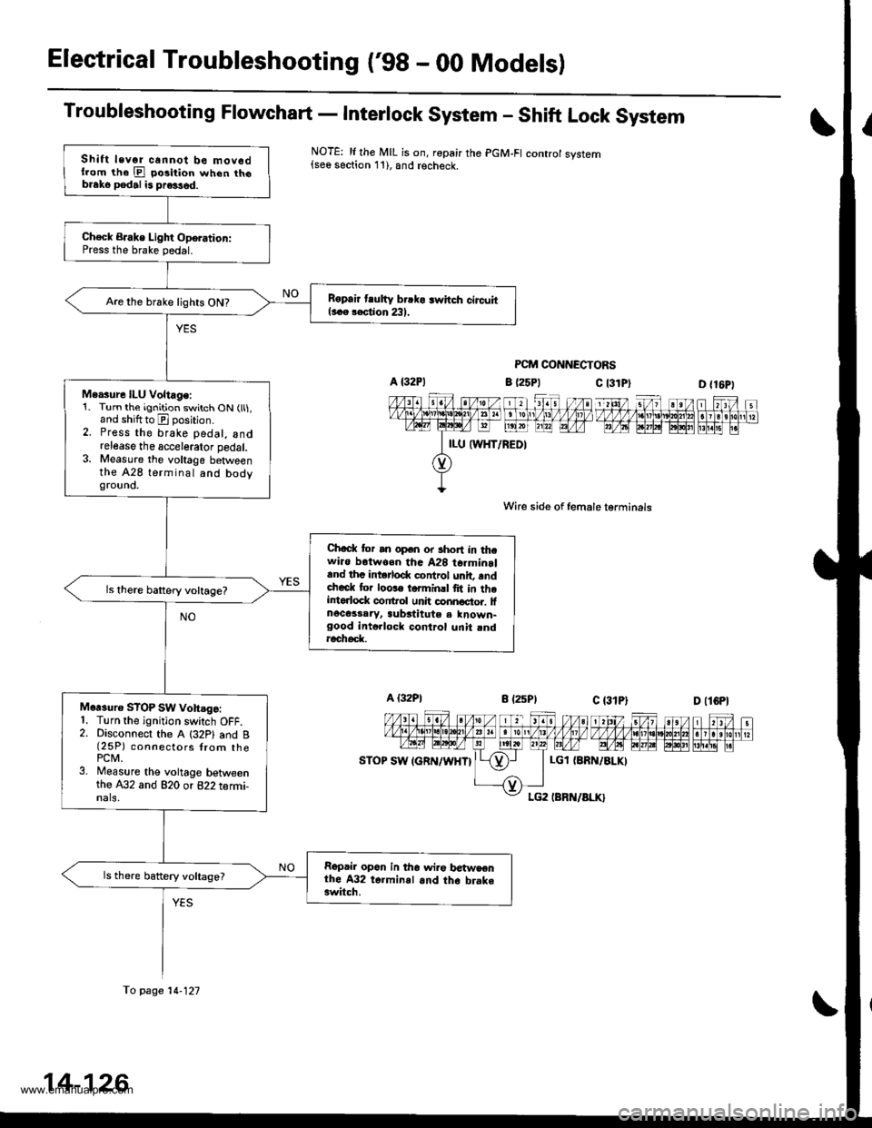
Electrical Troubleshooting ('98 - 00 Modelsl
Troubleshooting Flowchart - Interlock System - Shift Lock System
NOTE: li the MIL is on, ropair the PGM-FI controt system{see section 11), and recheck.
PCM CONNECTORS
c l3lPl
Wire side of female lerminals
c t3lPt
D {16P1
1 tttt/ 5t/ 1 a t /tlt 1 t\/t ,/ VVV tl t ttj,r\1e\10l211n . I 3 rholr1 t?m@-@Effilil"
D (lCPl
| 2ttt/ ;t /n) ).tt)/ 1 21:/ tvvvvv nnvl.lnl2
I r r ero
12wE gp]P] polr EI!l!!i r.
a (25P1
LGl {8RN/ALKI
Shift levor cannot be mov6dllom the E po3ition when th6blako pedal is pre3sed.
Ch€ck BJake Light Oporation:Press the brake pedal.
B6pair tlutty brrko 3whch circuitl..e rection 231.Are the brake lights ON?
Me.sure ILU Voltage:1. Turn the ignition switch ON (ll1,and shiftto E position.2. Press the brake pedal, andrelease the accelerator pedal.3. Measure the voltage betweenthe A28 terminal and bodygrouno.
Chock tor an open or short in thewi.o botwoen tha A28 t6rminrland thc intorlod( control unit, rndcheck tor loose torminrl fit in theintorlock conftol unh connoctor. lfnocassaryr aubstitute a known-good intollock control unit rndroch6d(
Mor3uro STOP SW vohsgo:1. Turn the ignition switch OFF.2. Disconnect the A (32P1 and B(25P) connectors {rom thePCM.3. Measure the voltage betweenthe A32 and 820 or 822 termi-nals,
Repair op6n in tho wir€ betwsenthe A32 t6.minal and th6 brake3witch.
ls there battery voltage?
fo page 14-121
14-126
www.emanualpro.com
Page 1182 of 1395
Connector ldentification and Wire Harness Routing
Main Wire Harness {Right side of dash and floor branchesl {cont,dl
Connector or
Tsrminal
Number ol
CavitiesLocationConnects toNotes
c427
c428
c429
c430
c431
c432
c433
c434
c435
c436
c436
c447
6
26
22
7
20
5
7
25Front passenger's door
Behind right kick panel
Behind right kick panel
Behind right kick panel
Behind right kick panel
Under right side of dash
Under .ight side of dash
Under middle of dash
Under middle of dash
Under middle of dash
Under middle of dash
Behind right kick panel
Front passenger's door wire harness(c671)
Right side wire harness {C601)ABS control unit
ABS control unit
Engine wire harness (C127)
PGM-Fl main relay
JUnotron connector
Tailgate open relay
Headlights f lasher relay
Heater sub-harness (C731 )Heater sub-harness (C731)
ECM/PCM
ABS
ABS
Optional
Optional'97 model'98 - 00
models'98 - 00
mooets
G402Under right side of dashBody ground, via main wire harness
23-22
www.emanualpro.com