Page 179 of 1395

1.
2.
3.
RemovaUlnspection/lnstallation
Drain the engine oil.
Turn the crankshaft, and align the white groove on
the crankshaft pulley with the pointer on the lower
cover.
Remove the cylinder head cover and middle cover.
Remove the power steering pump belt, air condi-
tioner belt and the alternator belt.
Remove the crankshaft pulley, and remove the
lower cover.
6. Remove the timing belt.
7. Remove the drive pulley.
8. Remove the oil pan and oil screen.
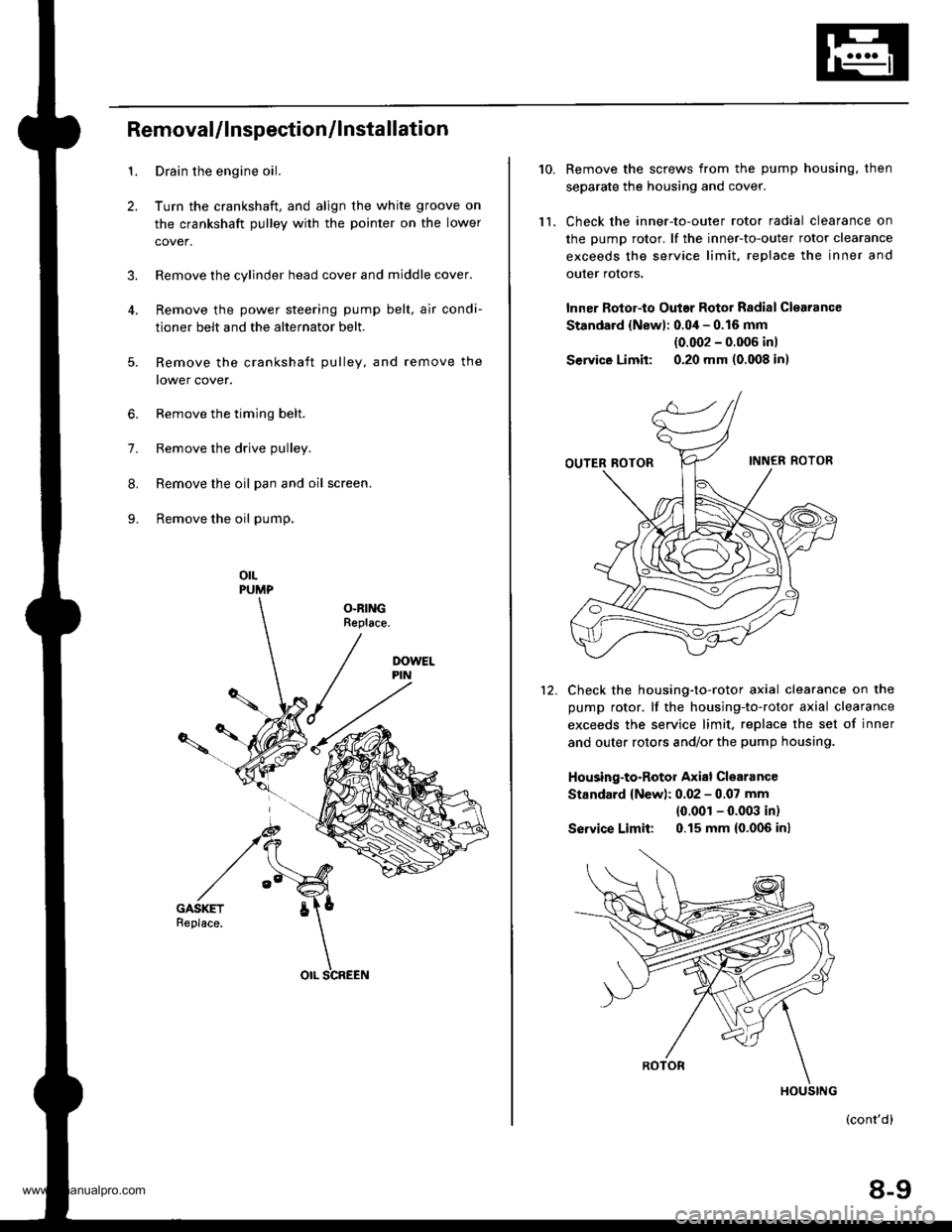
9. Remove the oil pump.
orLPUMP
OLRINGReplace.
5.
OIL SCREEN
10.
ll.
Remove the screws from the pump housing, then
separate the housing and cover.
Check the inner-to-outer rotor radial clearance on
the pump rotor. lf the inner-to-outer rotor clearance
exceeds the service limit. replace the inner and
outer rotors.
lnner Rotor-to Outar Rotor Radial Clearance
Standard {Newl: 0.04 - 0.16 mm
{0.002 - 0.006 inl
Service Limit: 0.20 mm (0.008 in)
Check the housing-to-rotor axial clearance on the
pump rotor. lf the housing-to-rotor axial clearance
exceeds the service limit. replace the set of inner
and outer rotors and/or the pump housing.
Housing-to-Rotor Axial Clearance
Standard {New): 0.02 - 0.07 mm
{0.001 - 0.003 in)
So|'�ice Limit: 0.15 mm (0.006 inl
(cont'd)
8-9
HOUSING
www.emanualpro.com
Page 180 of 1395

Oil Pump
13.
Removal/lnspection/lnstallation (cont'd)
Check the housing-to-outer rotor radial clearance. lf
the housing-to-outer rotor radial clearance exceeds
the service limit, reDlace the set of inner and outer
rotors and/or the pump housing,
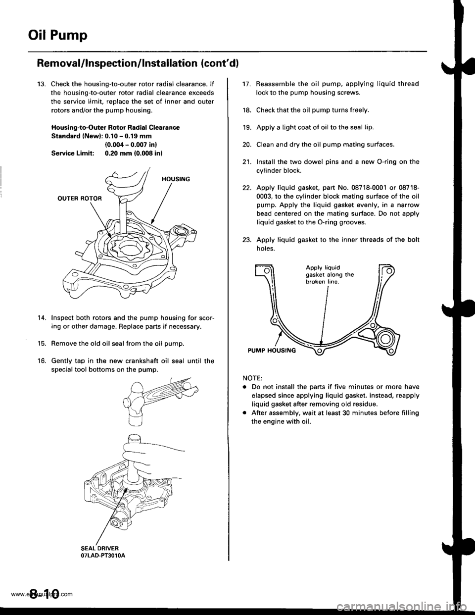
Housing-to-Outer Rotor Radial Clearance
Standard lNewl: 0.10 - 0.19 mm
{0.004 - 0.007 in}
Service Limit: 0.20 mm {0.008 inl
Inspect both rotors and the pump housing for scor-
ing or other damage. Replace pans if necessary.
Remove the old oil seal from the oil pump.
Gently tap in the new crankshaft oil seal until the
special tool bottoms on the pump.
14.
15.
16.
8-10
17.Reassemble the oil pump, applying liquid thread
lock to the pump housing screws.
Check that the oil pump turns freely.
Apply a light coat ot oil to the seal lip.
Clean and dry the oil pump mating surfaces.
Install the two dowel pins and a new O-ring on the
cylinder block.
Apply liquid gasket, part No. 08718-0001 or 08718-
0003, to the cylinder block mating surface of the oil
pump. Apply the liquid gasket evenly, in a narrow
bead centered on the mating surface. Do not apply
liquid gasket to the O-ring grooves.
Apply liquid gasket to the inner threads of the bolt
noles.
18.
19.
20.
21.
Apply liquidgasket along thebroken line.
PUMP HOUSING
NOTE:
. Do not install the pans if five minutes or more have
elapsed since applying liquid gasket. Instead, reapply
liquid gasket after removing old residue.
. After assembly, wait at least 30 minutes betore filling
the engine with oil.
www.emanualpro.com
Page 205 of 1395
Special Tools
Ref. No. Tool NumberDescriptionOty Page Reference
q
t3'
,3)l
6rl
A973X_041 _XXXXX
07JAZ 0010008
07PAZ , 0010100
07sAz - 001000A
07405 - 0040001
Vacuum Pump/Gauge,0 - 30 in.Hg
Vacuum/Pressure Gauge, 0 4 in.Hg
SCS Service Connector
Backprobe Set
Fuel Pressure Gauge
1
1
2
1
'11-201 . 208,214,
215,2't6,217 ,220,
221 , 222, 223, 224
11 207 , 224
11-60, 83, 88, 1 16,
128,200,205
11-62
11-178, 181
Special Tools
I
11-2
www.emanualpro.com
Page 208 of 1395
DATA LINK CONNECTOR {DLC) I16P}Troubleshooting Procedures, page 1 1'60PRIMARY HEATED OXYGEN SENSOR
{PRIMARY HO2SI {SENSOR 1)Troubleshooling, page 11 110
SECONDARY HEATED OXYGENSENSOR{SECONDARY HO2S) {SENSOR 2)Troubleshooting, page 1 1-1 17
'97 - 98 models:
AIR CLEANERReplacement, page 1 1'194
Troubleshooting, page 1 'l -200
THROTTLE BODY (TB)Inspection, page 11 196Removal, page 11-197Disassembly, page 1 1-'198
POWERTRAIN CONTROL MODULE(PCM) (A/TI
Troubleshooting Procedures, page 1 1-60Troubleshooting. page 1 1'82
THROTTLE CABLEInspection/Adjustment, page 1 1-1 94Installation, page 11- 195
VENTILATION (PCV) VALVEInspection, page 1 1-201FAST IDLEVALVE (A/T}
(cont'd)
1 1-5
PGM-FIMAIN RELAYRelay Testing, page 11-l87Troubleshooting. page 1'1 188
SERVICE CHECK CONNECTOR {2PITroubleshooting Procedures, page 1 1-60
,a'=_-_
WAY CATALYTIC
Inspection, page 1 1-168
www.emanualpro.com
Page 218 of 1395
Electrical Connections -'97 Model
f_ --- --- -t _l-1r -lla^^^ tirrnl
(.J
no 3wrcx (-]lrLt -'o.:\-'tlDl"ii
\
HT:
v
l-I
tl
I-6,
I
4
' ^li lGPlf----;;ltl
tl
T
FUEL ll'tlEcToes
oa 9I3
aEt30F
TDC3ErcON
ctPSErAOi
CKF3EN30F
TO EIIF-
*f
ctovEu
A' lGI
aztL@,
Xo.2|NJ2 3
ca tDcP[{J3 A2
cra Tltcl
||tL
Gt ct(iP?
er2 cxP{
cfl ct(Ftr
1
Dta ELtr
c|| v!]3TL T'
t ^cc ^r?to l/C CLUTCfl BELAYto i^Ol^toh F tl REI Y,@III'C|{AEi FA'I iEL Y
rtT
c. K.uirEuNxcoi||lEctoh
SERVICECl|ECK@ NEqroi
I ^ca 6
d__-lb
qr 3c3
ilaALTF CI'
rt: usAEII ATPI{PE
6uI)r^ l
t*frl
E
t'-
bI. ATPfi
B2a AtPtX
E' TPDI
Att lEFOgn3wltc
gi7 alP:l
I
I
ON
Ei. ATPID{ND tir
FUSES :(D BACK uP (RADro) (7.sr0.
@ "o^n ttot (tuo)'(D BATfERY (IOOA) *
o rcl (4oA)*
GAIXIEASSEIBLY
(DFt E/ flsA).@ No.13 FUEL PU P ('l5A)
O No. 2s METER (7.5A)(D NO. 'I5 ALTERNATOR SP SENSOB (7.5A) *
O No. 3i STABTER SIGNAL (7.5A)*: In lhc und?r.lrood tu$/rclay bor
(cont'd)
1 1-15
www.emanualpro.com
Page 262 of 1395

Troubleshooting
Troubleshooting Procedures
How To Begin Troubleshooting
When the Malfunction indicator Lamp (MlLl has been reported on, or there is a driveability problem, use the appropri-ate procedure below to diagnose and repair the problem.
A. When the MIL has come on:
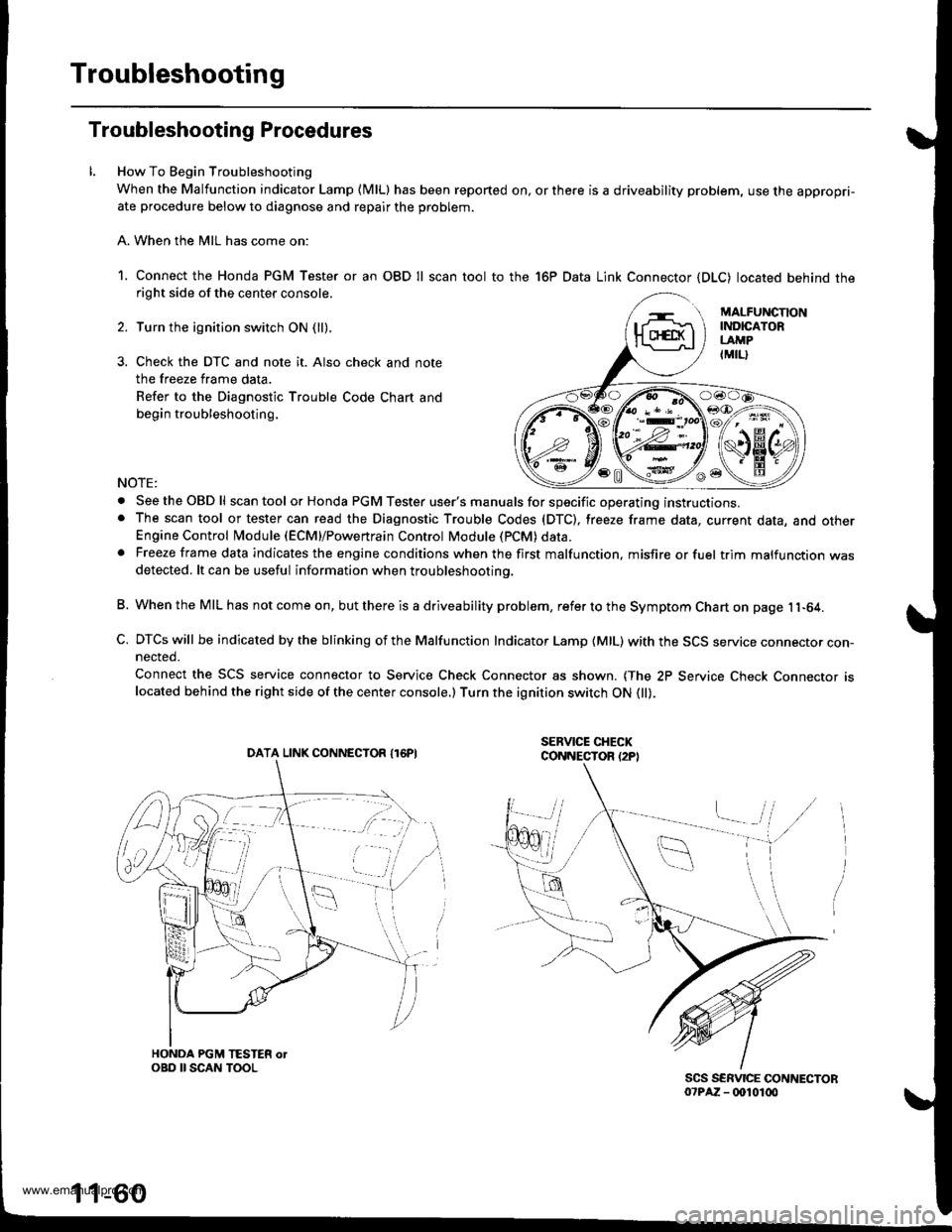
1. Connect the Honda PGM Tester or an OBD Il scan tool to the 16P Data Link Connector (DLC) located behind theright side of the center console.
Turn the ignition switch ON (ll).
Check the DTC and note it. Also check and note
the freeze frame data.
Refer to the Diagnostic Trouble Code Chart and
begin troubleshooting.
NOTE:
. SeetheOBDll scan tool or Honda PGM Tester user's manuals for specific operating instructions.. The scan tool or tester can read the Diagnostic Trouble Codes (DTC), freeze frame data, current data, and otherEngine Control Module (ECM}/Powertrain Control Module (PCM) data.. Freeze frame data indicates the engine conditions when the first malfunction, misfire or fuel trim malfunction wasdetected. lt can be useful information when troubleshootino.
B. When the MIL has not come on, but there is a driveability problem, refer to the Symptom Chart on page 11-64.
C. DTCs will be indicated by the blinking of the Malfunction Indicator Lamp {MlL) with the SCS service connector con-nected.
Connect the SCS service connector to Service Check Connector as shown. {The 2P Service Check Connecror rslocated behind the right side of the center console.) Turn the ignition switch ON 0l).
DATA LINK CONNECTOR I16PI
1 1-60
www.emanualpro.com
Page 263 of 1395
ll. Engine Controt Module (EcM)/Powertrain Control Module {PCM) Reset Procedure
Either of the following actions will reset the ECM/PCM.
. use the oBD ll scan tool or Honda PGM Tester to clear the ECM'�s/PCM'�s memory. (see the oBD ll scan tool or
Honda PGM Tester user's manuals for specific operating instructions )
. Turn the ignition switch oFF. Remove the BACK UP (RADIO) (7.5 A) fuse from the under-hood fuse/relay box for 10
seconos.
lll. Final Procedure {this procedure must be done after any troubleshooting)
1. Remove the SCS Service Connector if it is connected. lf the SCS service connector is connected. and there are no
DTCS stored in the ECM/PCM, the MIL will stay on when the ignition switch is turnsd oN (ll).
2. Do the ECM/PCM Reset Procedure.
3. Turn the ignition switch OFF
4. Disconnect the OBD ll scan tool orHonda PGM Tester from the Data Link Connector ( 16P)'
(cont'd)
1 1-61
BACK UP {RADIOI I7,5 AI FUSE
FUSE/RELAY BOX
www.emanualpro.com
Page 271 of 1395

PCM CONNECTOR C (31PI
ferminalnumberWirecolorTerminalnameDoscriptionSignal
'tBLUiREDCKFP (CKF SENSOR PSIDE)Detects CKF sensor.With engine running: pulses
2BLUCKPP (CKP SENSOR PSIDE)Detects CKP sensor.With engine running: pulses
3GRNTDCP (TDC SENSOR PSIDE)Detects TDC sensor.With engine running: pulses
4YELCYPP (CYP SENSOR PSIDE)Detects cYP sensor.With engine running: pulses
5BLU,frEDACS (A/C SWTTCHSIGNAL)Detects A,/C switch signal.With AJC switch ON: 0 VWith A,/C switch OFF: battery voltage
BLU/ORNSTS (STARTER SWITCHSIGNAL)
Detects starter switch signal.With starter switch ON (lll): bafteryvoltageWith staner switch OFF: 0 V
7BRNSCS (SERVICE CHECKSIGNAL)
Detects service check connectorsignal (the signal causing a DTCindication)
With the connector connected: 0 V
With the connector disconnected: about
5 V or battery voltage
8LT BLUK-LINESends and receives scan toolsrgnal.With ignition switch ON (ll): pulses
10WHT/BLUVBUUP)
(VOLTAGE BACKPower source tor the PCMcontrol circuit. Power source for
the DTC memory
Battery voltage at all times
11WHT/REDCKFM (CKF SENSOR MSIDE)Ground for CKF sensor signal.
12WHTCKPM (CKP SENSOR I\4SIDE)Ground lor CKP sensor signal.
13REDTDCM (TDC SENSOR MSIDE}Ground for TDC sensor signal.
14BLKCYPM (CKP SENSOR MSIDE}Ground for CYP sensor signal.
16GRN
PSPSW (P/S PRESSUREswtTcH)Detects PSP switch signal.At idle with steering wheel in straightahead position:0 VAt idle with steering wheel at full lock:
battery voltage
17WHT/REDALTF (ALTERNATOR FRSIGNAL)
Detects alternator FR signal.With fully warmed up engine running:
0 V-battery voltage {depending onelectrical load)
18BLUA/VHTVSS (VEHICLE SPEEDSENSOR)Detects VSS signal.Wirh ignition switch ON (ll) and frontwheels rotating: cycles 0 V - 5 V or bat-tery voltage
Wire side of femaie terminalsPCM CONNECTOR C {31PINOTE: Standard battery voltage is 12 V.
(cont'd)
www.emanualpro.com