Page 687 of 1395
13.Pry the right driveshaft out of the differential. and
orv the left driveshaft out of the intermediate shaft
{see section 16).
Pull out the inboard joint, and remove the right and
left driveshaft (see section 18).
Tie plastic bags over the driveshaft ends. Coat all
Drecision finished surfaces with clean engine oil.
Disconnect the primary heated oxygen sensor
(Primary HO2S) connector.
Remove exhaust pipe A.
GASKETReplace.
14.
16.
't7 .
ORIVESHAFT
Replace.
EXHAUST
14-171
18.
19.
Remove the shift cable cover.
Remove the shift cable.
ilWD:
Remove the snap pin and control pin, then separate
the shift cable from the control lever. Do not bend
the shift cable excessively.
2WD:
Remove the control lever, then separate the shift
cable from the control shaft. Do not bend the shift
cable excessivelv.
Replace.
SHIFT CAELE
www.emanualpro.com
Page 714 of 1395

Secondary Valve Body
Disassembly/lnspection/Reassembly
NOTE:
' clean all parts thoroughly in solvent or carburetor cleaner. and dry them with compressed air. Blow out aU passages,. Replace the valve body as an assembly if any parts are worn or damaged.t check all valves for free movement. rf anyfair to sride freery. see varve Body Repair on page 14-192.. Coat all parts with ATF during reassembly.. The CPC valve is installed in the secondary valve body, held in place by the lock bolt.
@,.-.t'tr.,
,rr'^'//u
"/ ./
3-' SHIFT VALVE
VALVE CAP
SPRING SPEC!FICATIONS
2.3 SHIFT VALVE
VALVE SLEEVE
ROLLER
ilTH EXHAUST VALVE
N"*,"o"*,
Unit: mm (in)
t*-1
SECONOARY VALVE BODYInspect for wear, scratches, andscorang.
3.4 ORIFICE CONTROL VAL
No.SpringsStandald {Nswl
Wire Dia.o.D.Free LengthNo. of Coils
o
@
o
@
3 4 shift valve spring
2-3 shift valve spring
4th exhaust valve spring
3-4 orifice control valve spring
0.9 (0.035)
0.9 (0.035)
0.9 {0.035)
0.6 {0.024}
7.6 (0.299)
7.6 (0.299)
6.1 (0.240t
6.6 (0.2601
57 .O i.2.2441
57 .O 12.244J
36.4 (1.433)
37.9 (1.492)
26.A
26.8
19.5
31.6
14-198
www.emanualpro.com
Page 778 of 1395
Transmission
Installation (cont'dl
2WD:
Install the control lever with a new lock washer to thecontrol shaft. Do not bend the shift cable excessivelv.
8 r 1.25 mm22 N.m|'2.2 kgt.m,16 rbf.ft)
SI{IFT CAELECOVER
LOCK WASHER 6 x 1.0 mmReplace. 14 N.m 11.4 kgt.m,10 tbr.frl
lnstallthe shift cable cover.
Install exhaust pipe A.
Connect the primary heated orygen sensor (primary
HO2S) connector.
GASKETSReplace.
22.
23.
10 x 1.25 m.n5r N.m {5.5 kgf.m,40 tbtftlReplace.
SELF.LOCKING
SELF-LOCKING NUT8 ! 1.25 mm16 N.m {1.6 kgf.m,12 lbf.fttReplace.
8 x 1.25 mm22 N.m {2,2 kgt.m, l5 lbt.ftl
SHIFT CABLE
14-262
24. Installthe splash shield and guard bar,
8 x 1.2524 N.m {2.a kgl.m,17 tbt.ftl
SPLASH SHIELD
GUARO BAR
25.
6r1.0|r|m9.8 N.m l1.0lgf.m, 7.2 tbtftl
Connect the mainshaft speed sensor, the shift con-trol solenoid valve, and the linear solenoid connec_tors,
SHIFT CONTROL SOLENOIDVALVE CONNECTOR
www.emanualpro.com
Page 1164 of 1395

Troubleshooting
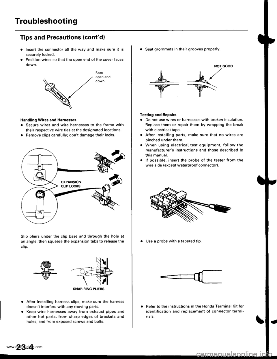
Tips and Precautions (cont'dl
Insen the connector all the way and make sure it is
securely Iocked.
Position wires so that the open end of the cover faces
down.
V
Faceopen end
Handling Wires and Harnesges
. Secure wires and wire harnesses to the frame with
their respective wire ties at the designated locations.
. Remove clips carefully; don't damage their locks.
Slip pliers under the clip base and through the hole at
an angle, then squeeze the expansion tabs to release the
clrD.
After installing harness clips, make sure the harness
doesn't interfere with any moving pans.
Keep wire harnesses away from exhaust pipes and
other hot parts, trom sharp edges of brackets and
holes. and from exoos€d screws and bolts.
NOT GOOD
A -M/
lr lr*
T€sting and Repairs
. Do not use wires or harnesses with broken insulation.
Replace them or repair them by wrapping the break
with electricaltape.
. After installing parts, make sure that no wires are
pinched under them.
. When using electrical test equipment, follow the
manufacturer's instructions and those described in
this manual.
. lf possible, insert the probe of the tester from the
wire side (except waterproof connector).
. Seat grommets in their grooves properly.
. Use a probe with a tapered tip.
Refer to the instructions in the Honda Terminal Kit for
identification and replacement of connector termi-
nals.
www.emanualpro.com