Page 837 of 1395

Rear Driveshafts
't.
Removal
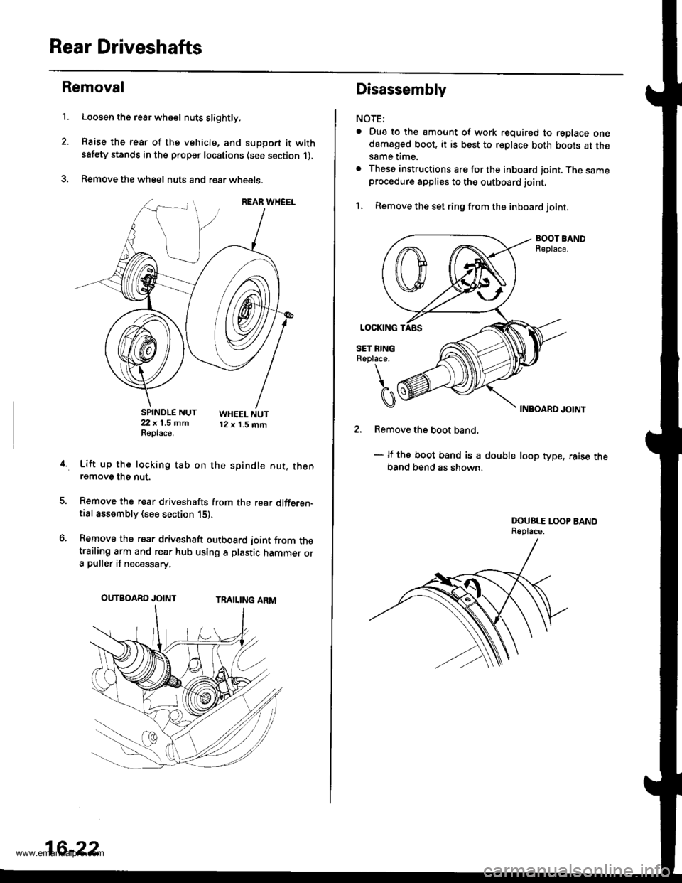
Loosen the rear wh€el nuts slightly.
Raise the rear of the vehicle, and support it withsafety stands in the proper locations (see section 1),
Remove the wheel nuts and rear wheets.
SPINDLE NUT22 x 1.5 mmReplace.
WHEEL NUT12 x 1.5 mm
4.Lift up the locking tab on the spindle nut. thenremove the nut.
Remove the rear driveshafts from the rear differen-tial assembly (see section 15),
Remove the rear driveshaft outboard joint from thetrailing arm and rear hub using a plastic hammer ora puller if necessary.
TRAILING ARMOUTBOARD JOINT
16-22
Disassembly
NOTE:
a Due to the amount of work required to replace onedamaged boot, it is best to replace both boots at thesame time.
. These instructions are for the inboard joint. The sameprocedure applies to the outboard joint.
1, Remove the set ring from the inboard joint,
BOOT BANDReplace.
INBOARD JOINT
2. Remove the boot band.
- lf the boot band is a double loop type, raise theband bend as shown,
DOUSLE LOOP BANDReplace.
www.emanualpro.com
Page 839 of 1395
Rear Driveshafts
CIRCLIP
Reassembly
Note these items during reassembly:
. Clean the disassembled parts with solvent, and dry them thoroughly with compressed air. Do not wash the rubberparts with solvent,
o r''..@El: Thoroughly pack the inboard joint and both joint boots with the joint grease included in the new driveshaftset.
Grease quantity:
f nboard Joint/Outboard Joint: 80 - 90 g 12.8 - 3.2 ozl
SET RINGReplace.
LEFT INBOARD JOINT(with small driveshaft ring)
BOOT BANOSBeplace.
DRIVESHAFT
RIGHT INBOARD JOINT(with large driveshaft ring)
Pack cavity with grease.
BOOT BANOSReplace.
.6{Pack cavity
\@
DRIVESHAFTRINGS
ROLI.ER
16-24
with grease.OUTBOARD JOINT
www.emanualpro.com
Page 841 of 1395
Rear Driveshafts
Reassembly (cont'd)
8. Install the joint by holdjng the driveshaft straight upand aligning the marks on the joint with the marks
on the rollers,
9.Adjust the position of the joints to the specificationsshown. then adjust the boots halfway between fullcompression and full extension. Make sure the endsof the boots are seated in the grooves in the joints.
Inboard ioint l€ngth:
153 - 157 mm {6.02 - 6.18 inl
Outboard ioint l6ngth:
l/l:' - 147 mm {5.63 - 5.37 in}
16-26
10. Set the double loop band onto the boot with theband end toward the front of the vehicle,
Pull up the slack in the band by hand.
Make a mark on the band 10 - 14 mm (0.4 - 0.6 in)from the clip.
11.
12.
CLIP
www.emanualpro.com
Page 843 of 1395
Rear Driveshafts
Reassembly (cont'd)
18. Install the new set ring into the driveshaft groove.
SET RINGReplace.
I
CI
SET RING GROOVE
16-2A
lnstallation
'1. lnstall the outboard joint into the trailing arm.
Install the rear driveshafts into the rear differential
assembly (see section 15).
Apply a small amount of engine oil to the seating
surface of the new spindle nut.
SPINDLE NUT 22 x 1.5 mm181 N.m (18.5 kgf.m, 134lbl.ftl Replace.
Install a new spindle nut, then torque the nut. After
tightening, use a drift to stake the spindle nut shoulder
against the driveshaft.
Clean the mating surfaces of the brake disc and the
wheel, then install the rear wheel, and torque the
wheel nuts.
WHEEL NUT 12 x 1.5 mm108 N.m (11.0 kgt.m, 80lbtftl
www.emanualpro.com
Page 845 of 1395

Propeller Shaft
RemovaUlnstallation
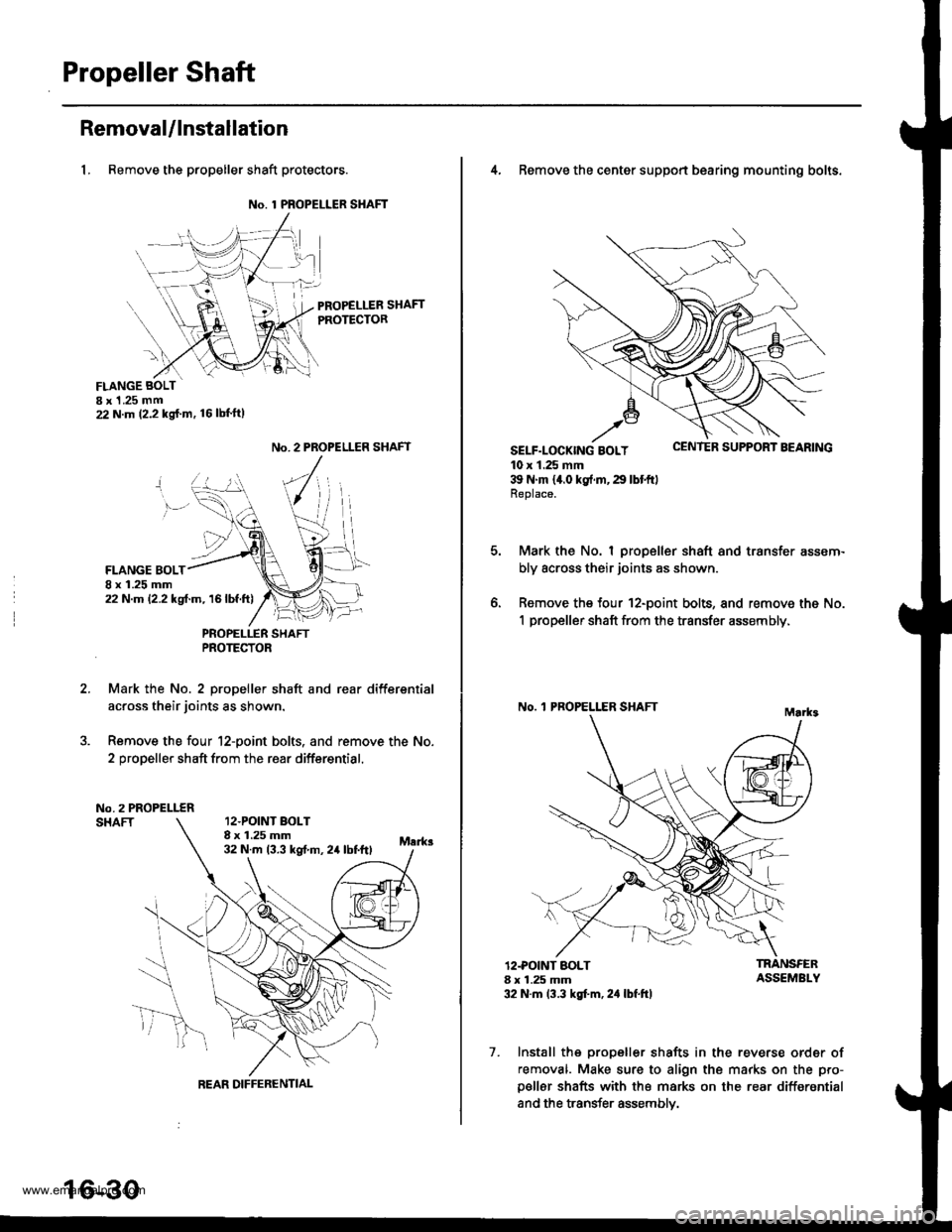
1, Remove the propeller shaft protectors.
No. 1 PROPELLER SHAFT
PROPELLER SHAFTPROTECTOR
FLANGE BOLTI x 1 .25 mm22 N.m (2.2 kg{.m. 16lbl'ft)
2.
No. 2 PROPELLER SHAFT
FLANGE BOLT8 x 1.25 mm22 N.m 12.2 kgf.m, 16lbf.ft)
PNOPELLER SHAFTPROTECTOR
Mark the No. 2 propeller shaft and rear differsntial
across their joints as shown.
Remove the four 12-point bolts. and remove the No.
2 propeller shaft from the rear differential.
No.2 PROPELLERSHAFT12.POINT BOLT8 x 1.25 mm32 N.m 13.3 kst m, 24 lbtftl
REAR DIFFERENTIAL
16-30
4, Remove the center support bearing mounting bolts.
SELF-LOCK|NG BOLT uErr rEn Durrr.r'r I I'EAnrNu
10 x 1.25 mm39 N'm 14.0 kg{.rn,29 lbtftlReplace.
Mark the No. I propeller shaft and transfer assem-
bly across their joints as shown.
Remove the four 12-point bolts, and remove the No.
1 propeller shaft from the transfer assembly,
No. 'l PROPELLER SHAFT
o.
12.POINT BOLT8 x 1.25 mm32 N.m 13.3 kgt'm, 2,1 lbf.ft)
TRANSFERASSEMBLY
7. Install the propeller shafts in the reverse order of
removal. Make sure to align the marks on the pro-
p€ller shafts with the marks on the rear differential
and the transfer assemblv.
www.emanualpro.com
Page 884 of 1395

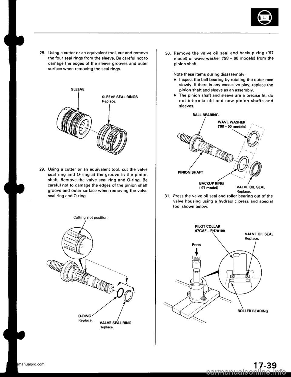
28. Using a cutte. or an equivalent tool, cut and remove
the four seal rings from the sleeve. Be careful not to
damage the edges ot the sleeve grooves and outer
surface when removing the seal rings.
Using a cutter or an equivalent tool. cut the valve
seal ring and O-ring at the groove in the pinion
shaft. Remove the valve seal ring and O-ring. Be
careful not to damage the edges of the pinion shaft
groove and outer surface when removing the valve
seal rjng and O-ring.
29.
SLEEVE
Cufting slot position.
30. Remove the valve oil seal and backup ring ('97
model) or wave washer ('98 - 00 models) from the
pinion shaft.
Note these items during disassembly:
. Inspect the ball bearing by rotating the outer race
slowly. lf there is any excessive play, replace the
pinion shaft and sleeve as an assembly.
. The pinion shaft and sleeve are a precise fit; do
not intermix old and new Dinion shafts and
sreeves,
WAVE WASHERl'98 - 0O modelsl
PINION SHAFT
BACKUP RING{'97 modellVALVE OIL SEAL
31.Replace.Press the valve oil seal and roller bearing out of the
valve housing using a hydraulic press and special
tool shown below.
BALL BEARING
PILOT COLLAR
ROLLER SEARING
www.emanualpro.com