Page 1107 of 1395
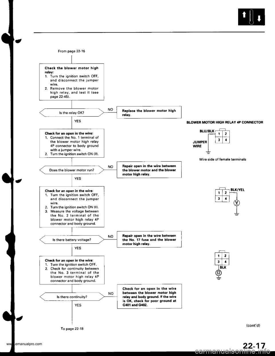
From page 22-16
Check lhe blower motor hightelay:1. Turn the ignition switch OFF,and disconnect the ju mper
2. Remove the blower motorhigh relay, and test it {seepage 22-45).
Check for rn opon in the wire:l. Connect the No. 1 terminal ofthe blower motor high relay4P connector to body ground
with a iumper wire.2. Turn the ignition switch ON (ll).
R6pair opcn in the wire botwoenthe blower motor and the blowermotoi high relry.Does the blower motor run?
Check tor an opon in the wire:'1. Turn the ignition switch OFF,and disconnect the iumper
2. Turn the ignition switch ON {ll).3. Meas0re the voltage betweenthe No. 2 terminal of theblower motor high relay 4Pconnector and body ground.
Repair opon in the wiro betweonthe No. 17 fuse and tho blowelmotor high relay.ls there battery voltage?
Check tor an open in the wire:'1. Turn the ignition switch OFF.2. Check lor continuity betweenthe No. 3 terminal ot theblower motor high relay 4Pconnector and body ground.
Check for an open in the wirebetween the blowar motor highrel.y and body ground. lf the wiroi3 OK, check fo. poor ground atG{Ol .nd Gt|()2,
To page 22-18
BLOWER MOTOR HIGH BELAY itP CONNECTOR
BLU/BLK rF r.--1 1 2 )l|_#
.ruuee" I l31i
wrRE I
Wire side of female terminals
(cont'd)
www.emanualpro.com
Page 1108 of 1395
Troubleshooting
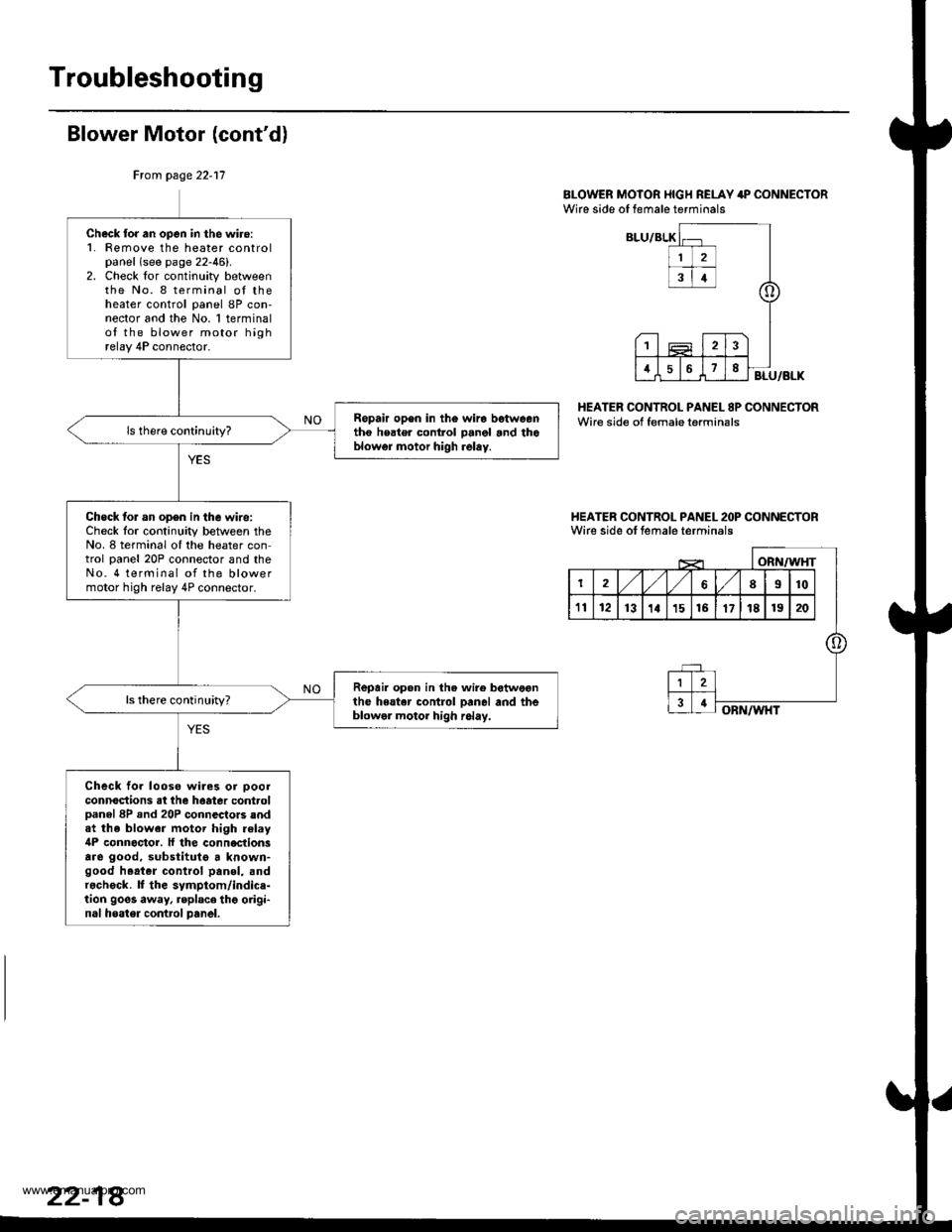
Blower Motor (cont'd)
BI-OWER MOTOR I{IGH RELAY 4P CONNECTORWire side of female terminals
HEATER CONTROL PANEL 8P CONNECTORWire side of female terminsls
I{EATER CONTROL PANEL 2OP CONNECTORWirc side ot female terminals
Ftom page 22-17
Check for an open in the wiro:1. Femove the heater controlpanel (see page 22-46).2. Check lor continuity betweenthe No. 8 terminal oI theheater control panel 8P con-nector and the No. 1 terminalof the blower motor highrelay 4P connector.
Ropair op6n in th€ wira betweentho heater control panol and thoblowgr motor high relay.
Check lor an op6n in the wire:Check lor continuity between theNo. 8 terminal oI the heater control panel 20P connector and theNo. 4 terminal of the blowermotor high relay 4P connector.
Repair open in the wire botweonthe heater control Danel and theblowel motor high r6lay.
ls there continuhy?
Check fo. looso wiles or ooolconnoctions at the haatea controlDanel 8P .nd 20P connectors andat the blower motor high relay4P connoctor. ll the conn€ctionsare good, substitutg a known-good h.at.r control panol, andr.check. lf the symptom/indice-tion goes away, replace thg origi-nal heater contrcl panel.
www.emanualpro.com
Page 1109 of 1395
Rcpbcc tho blower motor rolay.
Ch.ck th. under-hood tu.o/rolaybox:Measur6 the voltage between theNo. 3 terminal ofthe blower motorrelay 4P socket and body ground.
Chack tor an open in the wilo:1. Turn the ignition switch ON (ll).
2. Measure the voltage betweenthe No. 4 terminal of theblower motor relav ,[P socketand body ground.
Ropair opon in the wirs botwoonth. No. 17 fu3o and th. blow6rmotol lolay.ls thore battery voltage?
Chack tor an opon in tho wilo:1. Turn the ignition switch OFF.2. Check for continuity betweenthe No. 2 terminal ot theblower motor relay 4P socketand body ground.
Chock tor !n opan in the wilebstween tha blowar motor ralaY.nd body ground. It tho wilc isOK, chock fol poor ground atG/Ol and G402.
Ropair opon in th. BLU/WHTwira batwaan lho blowor motolrohy and tho blowe. motor.
Frcm page 22-16
BLOWER MOTOR RELAY 4P SOCKET
922-1
www.emanualpro.com
Page 1110 of 1395
Troubleshooting
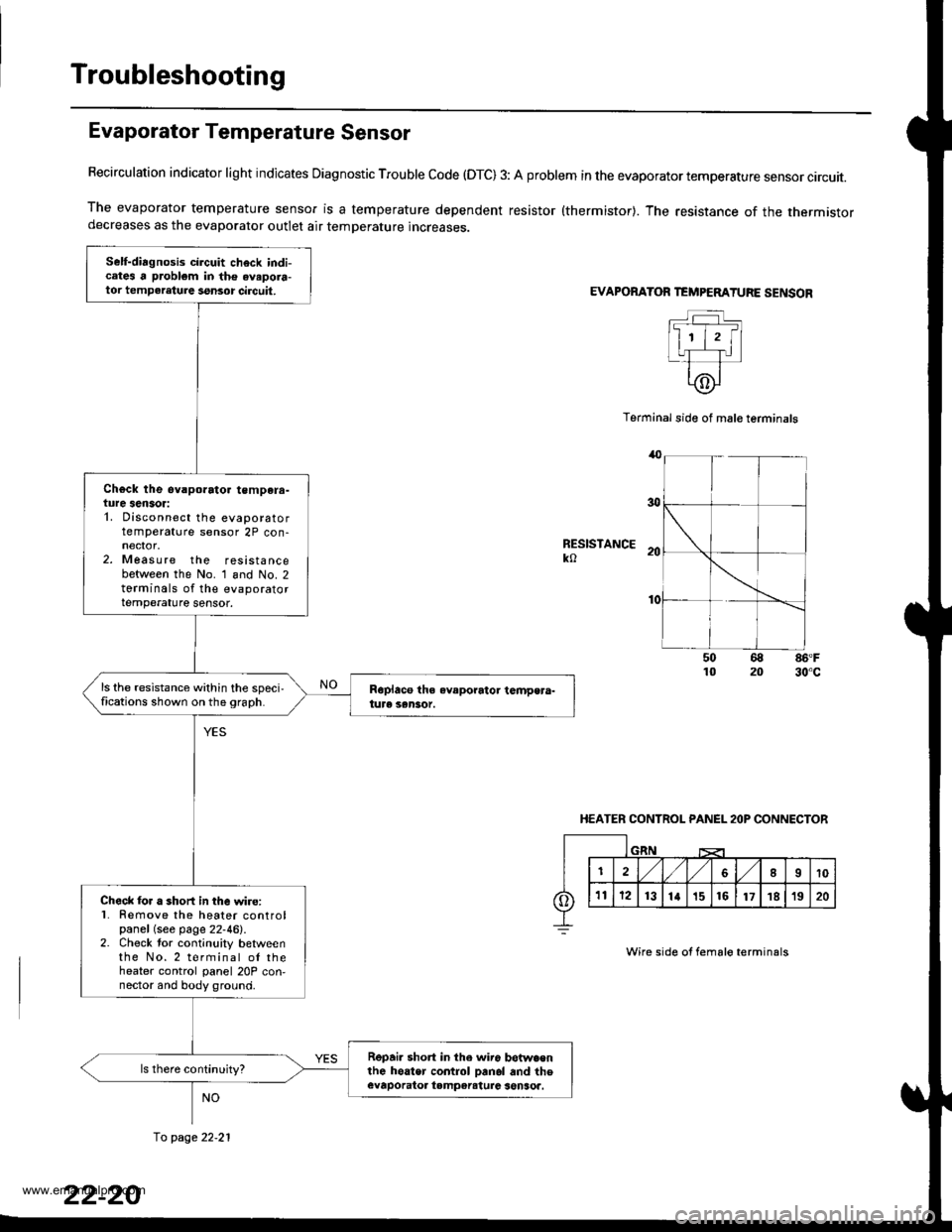
Evaporator Temperature Sensor
Recirculation indicator light indicates Diagnostic Trouble code (OTC) 3: A problem in the evaporator temperature sensor circuit.
The evaporator temperature sensor is a temperature dependent resistor {thermistor}. The resistance of the thermistordecreases as the evaporator outlet air temperature increases.
EVAPORATOR TEMPEMTURE SENSOR
Terminal side of mal€ terminals
RESISTANCEko
86'F30"c
HEATER CONTROL PANEL 2OP CONNECTOR
Wire side of fema16 terminals
Self-diagnosis circuit check indicates a problem in the avapora-tor tempeleture ssnsor circuit,
Ch€ck the ev.porato. tempera-ture sensor:1. Disconnect the evaporatortemperature sensor 2P con-
2. Measure the resistancebetween the No. 1 and No. 2torminals of the evaporatortemperature sensor.
ls the resistance within the speci,fications shown on the 9raph.
Check lor a short in the wire:l� Remove the heater controlpanel (see page 22-46).2. Check tor continuity betweenthe No.2 terminal ol theheater control panel 20P con,nector and body ground.
Repai. short in the wir6 betwa€nlhe hoater control Danol and theevaporatoa tampereturc senSoa.
fo page 22.21
www.emanualpro.com
Page 1111 of 1395
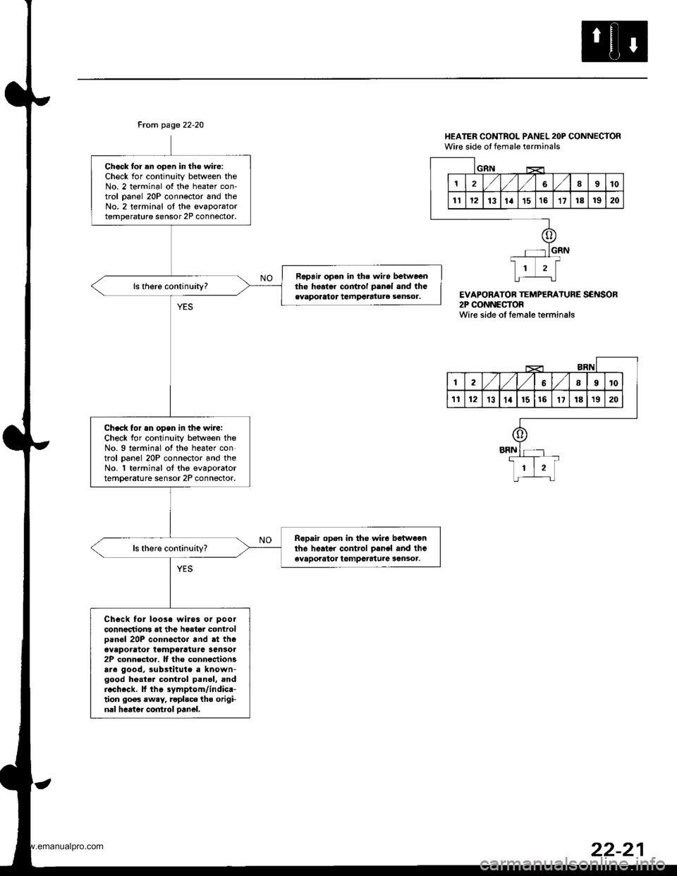
From page 22-20
Chock tor an oDen in th€ wire:Check for continuity betlveen theNo. 2 terminal of the heater con-trol oanel 20P connector and theNo.2 terminal oI the evaporatortemperature sensor 2P connoctor.
Fopair open in the wiro betweentho heato. control penel and theevaporator tempetatule sensor.
Check for rn opsn in tha wiJe:Check for continuity between theNo. 9 terminal of the heater control oanel 20P connector and theNo. 'l terminal ot the evaporatortemperature sensor 2P connector,
Ropair open in tho wire betwegnthe heater control oanel and theevaporator tgmpcrature sen3or.
Chgck fol loose wiros or pool
connectrons at the hoator controloan6l 20P connector and at theeveporator temperatura Sensol2P connector. It the connectionsare good, substitute a known-good he.tel contlol panel, andrech€ck. ll thg symptom/indica-tion 90o3 rwey, roplsce the origi-nal heater control oanel.
HEATER CONTROL PANEL 2OP CONNECTORWire side ol female terminals
EVAPORATOB TEMPERATURE SENSOR2P CONNECTORWire side oI temale terminals
1810
1112131a1516't7181920
GIIN
12,/ l,/689t0
'tl1213lat1516'1718't920
o
+
li-L:t
www.emanualpro.com
Page 1112 of 1395
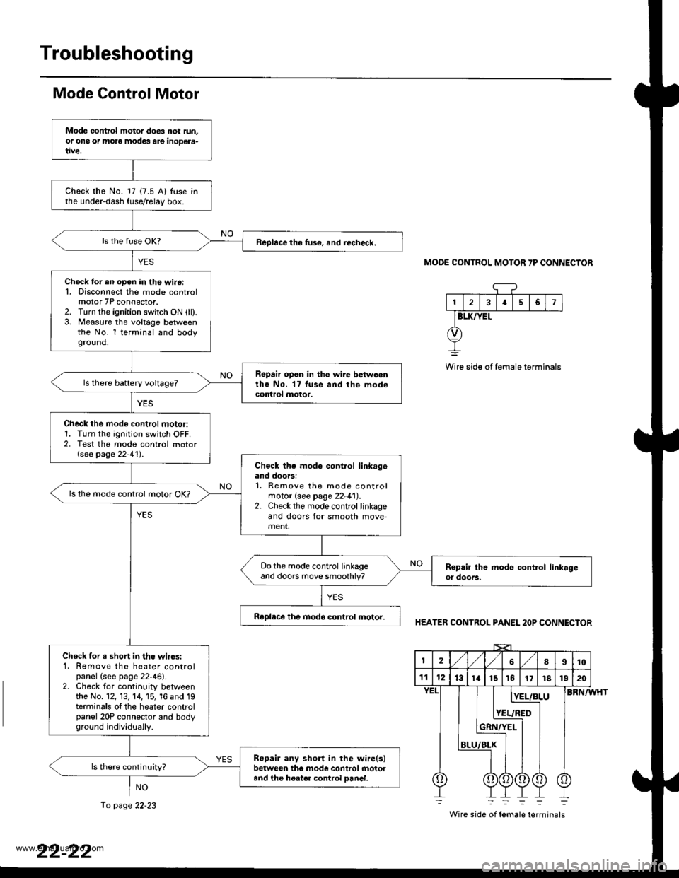
Troubleshooting
Mode Control Motor
NO
MODE CONTROL MOTOR 7P CONNECTOR
13I5
BLK/YEL
Wire side of female terminals
HEATER CONTROL PANEL 2OP CONNECTOR
BRN/WHT
Wire side of female terminals
Mode control motol does not run.or ono or more modes are inoD€aa-
Check the No. 17 {7.5 A) Iuse inthe under-dash fuse/relay box.
Replace the tus€, snd iecheck.
Chock tor an open in th€ wi.6:1. Disconnect the mode controlmotor 7P connector.2. Turn the ignition switch ON (ll).3. Measure the voltage betweenthe No. l terminal and bodyground.
Repair opon in the wire betwoontho No. 17 luse and tho modecontrol motor.
Check the mode control motor:1. Turn the ignition switch OFF.2. Test the mode control motorGee page 22 41') .
Chock th€ mode cont.ol link.geand doors:1. Remove the mode controlmotor (see page 22-41).2. Check the mode control linkageand doors for smooth move-ment,
ls lhe mode control motor OK?
Do the mode control linkageand doors move smoothly?
Replece the inod6 control motor.
Chock for s shon in the wir€s:1. Remove the heater controlpanel (see page 22'46).2. Check for continuity betweenthe No. 12, 13, 14, 15, 16 and 19terminals ol the heater controlpanel 20P connector and bodyground individuaily.
Repair any short in the wire(slbetween the mode control rnotoaand the h6ater control Danel.
ls there continuity?
2l,/1,/8I10
111213ta151617r81320
BLU
[E!r!
YEL/RED
Ii
To page 22-23
www.emanualpro.com
Page 1113 of 1395
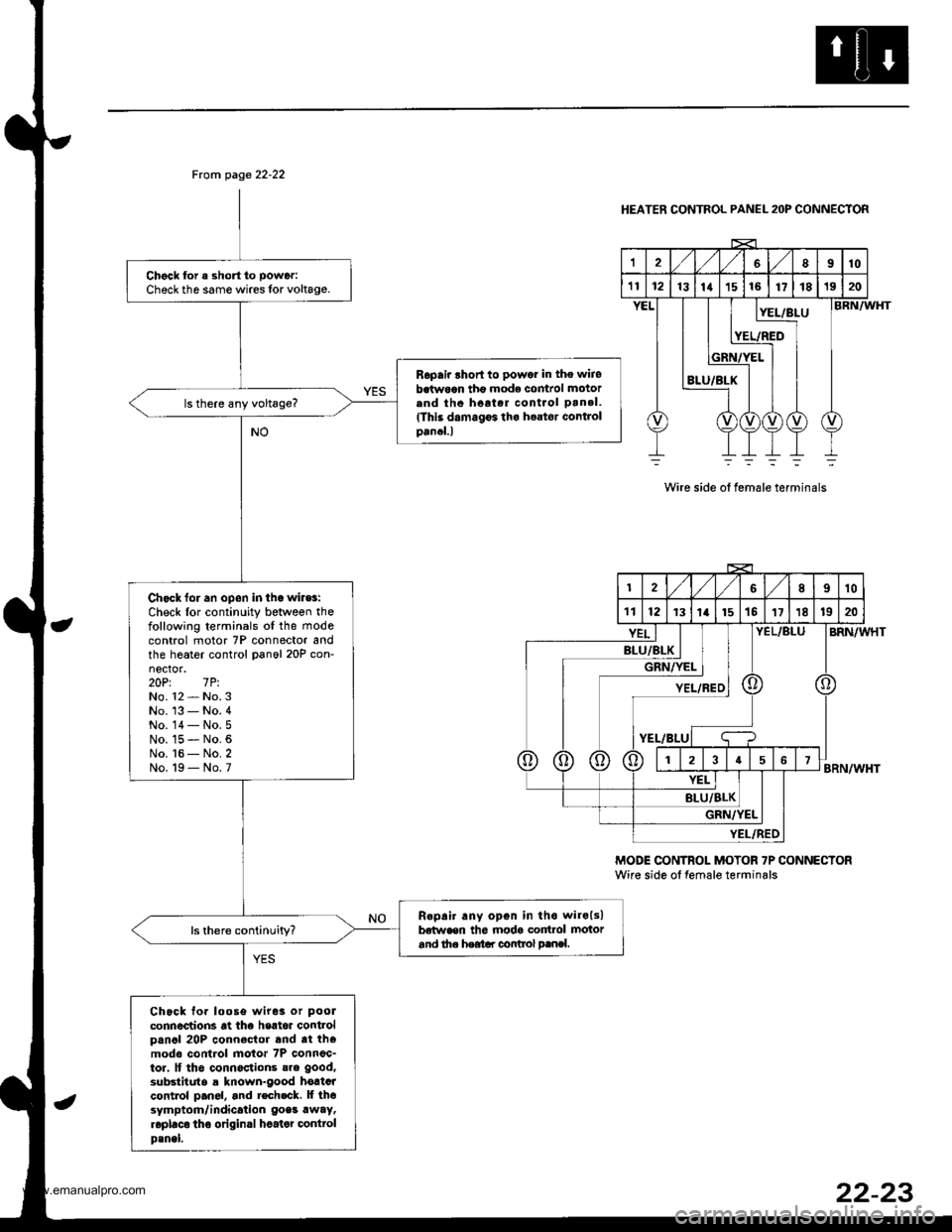
From page 22-22
Chgck for a short to power:
Check th6 same wires lor voltage.
Ropair lhort to powor in the wiiobetw6an tho mode comrol motorend thc hoat.r cont.ol pan.l.(This damagF tha h€ator Gontrolpancl.l
Chack for an opon in tha wiles:Check lor continuity between thefollowing terminals oI the mode
control motor 7P connector andthe heater control panol 20P con-nector.20Pt 7P.No. 12 - No. 3No. '13 - No. 4No. 14- No.5No. 15 - No. 6No. t6 - No. 2No. 19 - No. 7
R.pair any opon in tho wilols)betwaen th6 modg cortrol motorand th. heatar control p.nsl.
Chock fo. loose wiret or pool
connections at the heat6r controlpancl 20P connector and tt themodo control motor 7P connoc-tor. lf tho connactions sre good,
substitute a known-good hortcrcontrol pan6l, and tech.ck. lf thesymptom/indication goes awaytroplaco tho original hcater @nttolp3nel.
HEATER CONTROL PANEL 2OP CONNECTOR
12'VVLgl8910
't112rslrrlrslre17181920
8LU/BLX
:L/BLUBRN/WHT
BRN/WHT
BRN/WHT
Wire side ot female terminals
MODE CONTROI- MOTOR 7P CONNECTORWire side ol temale terminals
2,/1,/l/II10
111213t14t151511181920
BLU/BL
GRi
YEL/
Kt I I|/YEL I IIYEL/REDI
t-BLUI q
;f;T;T;
YEL/BLU
YEL
BLU/BLK
GRN/ItEL
YI:L/FED
22-23
www.emanualpro.com
Page 1114 of 1395
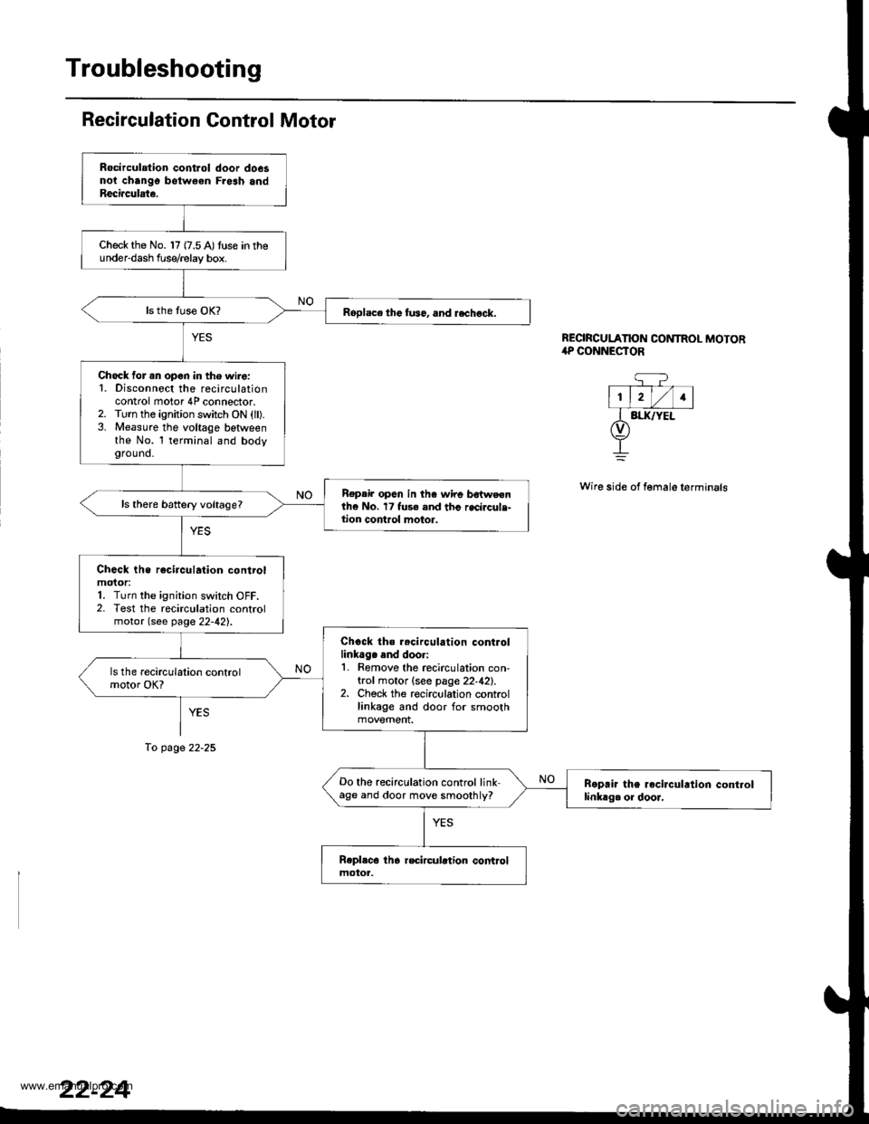
Troubleshooting
Recirculation Gontrol Motor
YES
To page 22-25
REORCULATION CONTROL MOTOR,rP CONNESTOR
q?- T--- V-l
l1, lrl/l1lI BI.IUYEL(v)
+
Wire side of female terminals
Rocirculation control door do6snoi chango botw€en Fresh andReci.culate.
Check the No. 17 {7.5 A)tuse in theunder-dash f use/relay box.
Roplace the fu36, and rechock.
Check for .n open in the wire:1. Disconnect the recirculationcontrol motor 4P connector.2. Turn the ignition switch ON (ll).3. Measure the voltage betlveenthe No. l terminal and bodyground.
Repair op6n in the wire bdtweenthe No. 17 fuse and thc recircule-tion control motor.
Check the rocirculation controlmoior:1. Turn the ignition switch OFF.2. Test the recirculation controlmotor (see page 22-42).
Chock ths r.circulation controllinkag. end doori1. Remove the recirculation con-trol motor (see page 22,42).2. Check the recirculation controllinkage and door for smooth
Do the recirculation control linkage and door move smoothly?Boprir the recirculrtion controllinkag. or dooJ,
www.emanualpro.com