1999 HONDA CR-V Replace battery
[x] Cancel search: Replace batteryPage 1210 of 1395
Battery
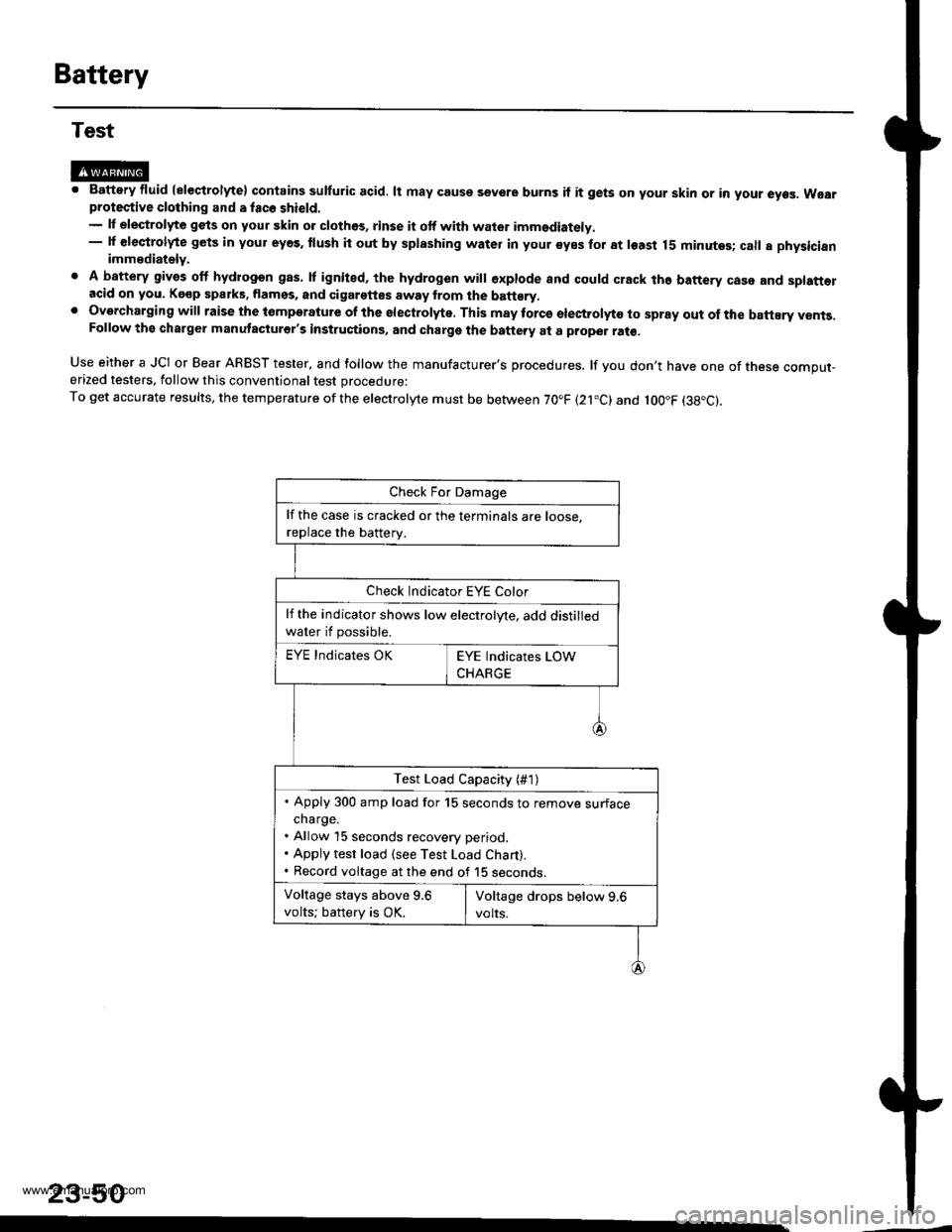
Test
@M. Battery fluid (eleqtrolyte) contains sulturic acid. lt may couse sevore burns if it gets on your skin or in your eyes. Wearprotective clothing and a fac6 shield.- lf elestrolyte gets on your skin o. clothos, rinse it otf with wator imm€diately.- lf €leqtrolyte gets in your eyes. tlush it out by splashing water in your syes for at least 15 minutes; call a physicianimmediately.
. A battery gives off hydrogon gas. lf ignited, the hydrogen will €xplode and could crack the battery case and splatt€racid on you. Kgop sparks. flamss, and cigarettes away from the batt€ry,. Overcharging will raise the tomperatute of the electrolyte. This may torcs electrolyto to spray out of the battEry vents,Follow the charger manutacturer's instructions, and charge the battery at a proper ral€,
Use either a JCI or Bear ARBST tester, and follow the manufacturer's procedures. lf you don't have one of tnese comput-erized testers, follow this conventional test procedure:
To get accurate results, the temperature ofthe electrolyte must be between 70.F (21.c) and loo"F (38"c).
23-50
lf the case is cracked or the terminals are roose.
replace the batterv.
Check Indicator EYE Color
lf the indicator shows low electrolyte, add distilled
water if possible.
EYE Indicates OK
Test Load Capacity (#1)
. Apply 300 amp load for 15 seconds to remove surfacecharge.. Allow 15 seconds recovery period.. Apply test load (see Test Load Chart).. Record voltage at the end of 15 seconos.
Voltage stays above 9.6
volts; battery is OK.
www.emanualpro.com
Page 1211 of 1395
(},
J-
BATTERY CODE
i
5582{LtS)-MF
J
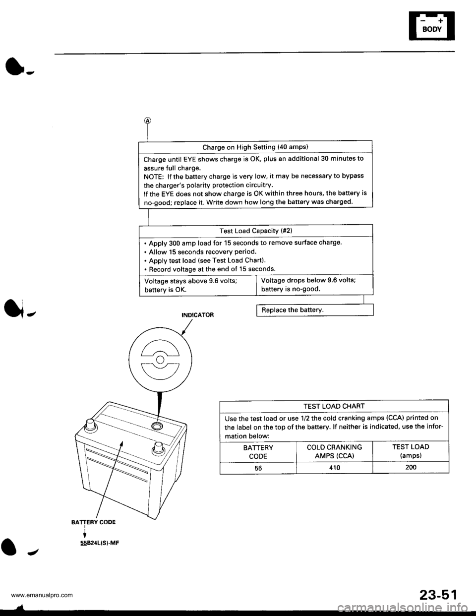
Charge on High Setting (40 amps)
Charge until EYE shows charge is OK, plus an additional 30 minutes to
assure Jull charge.
NOTE: lf the battery charge is very low, it may be necessary to bypass
the charger's polarity protection circuitry.
lf the EYE does not show charge is OK within three hours, the battery is
no-good; replace it. Write down how long the battery was charged.
Test Load Capacity (#2)
. Apply 300 amp load for 15 seconds to remove surface charge.
. Allow 15 Seconds recovery period,
. Apply test load (see Test Load Chart).
. Record voltage at the end ot 15 seconds.
Voltage drops below 9.6 volts;
battery is no-good,Voltage stays above 9.6 volts;
battery is OK.
TEST LOAD CHART
Use the test load or use 1/2 the cold cranking amps (CCA) printed on
the label on the top of the battery. lf neither is indicated. use the infor-
mation below:
BATTERY
CODE
COLD CRANKING
AMPS (CCA)
TEST LOAD
{amps)
55410200
J
23-51
www.emanualpro.com
Page 1214 of 1395
lgnition Switch
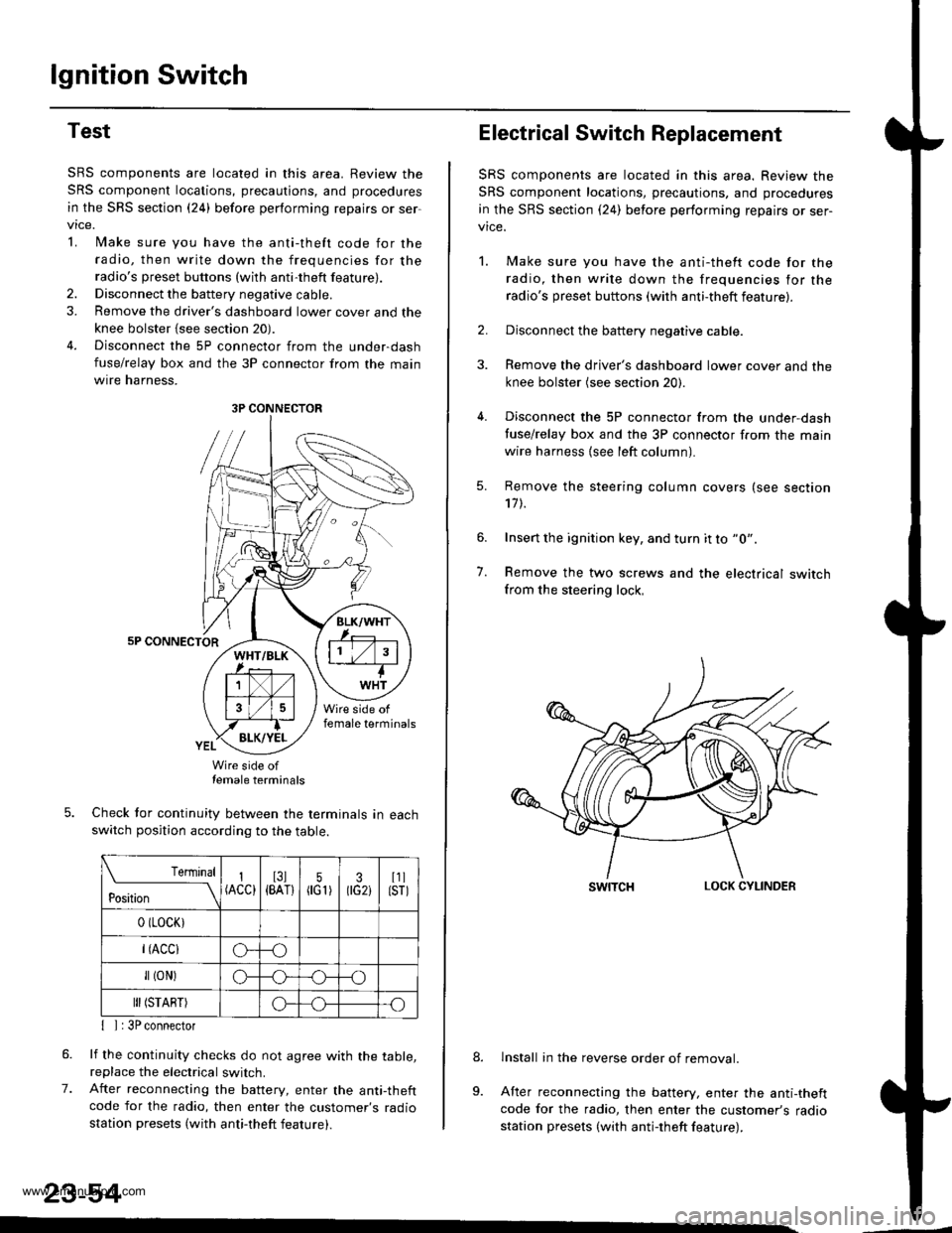
Test
SRS components are located in this area. Review the
SRS component locations, precautions, and procedures
in the SRS section {24} before performing repairs or ser
vtce.
L lMake sure you have the anti-theft code for the
radio, then write down the frequencies for theradio's preset buttons (wilh anti-theft feature).
2. Disconnect the battery negative cable.
3. Remove the driver's dashboard lower cover and the
knee bolster {see section 20).
4. Disconnect the 5P connector from the under-dash
fuse/relay box and the 3P connector from the main
wtre narness,
5P CONNECTOR
Wire side oftemale terminals
Check tor continuity between the terminals in eachswitch position according to the table.
rernrnal
ros[ron \
I(ACC)I3l{BAT}5flG1)30G2iI1llsrl
0 (LocK)
r(Acclo--o
fl (oN)G_o
III (START)o--.o
7.
{ I | 3P connector
lf the continuity checks do not agree with the table,replace the electrical switch.
After reconnecting the battery, enter the anti-theftcode for the radio, then enter the customer's radio
station presets (with anti-theft feature).
23-54
3P CONNECTOR
Electrical Switch Replacement
SRS components are located in this area. Review the
SRS component locations, precautions, and procedures
in the SRS section {24) before performing repairs or ser-vice.
1. Make sure you have the anti-thett code for the
radio, then write down the frequencies for the
radio's preset buttons (with anti-theft feature).
2. Disconnect the battery negative cable.
3. Remove the driver's dashboard lower cover and the
knee bolster (see section 20).
4. Disconnect the 5P connector from the under,dash
tuse/relay box and the 3P connector f.om the main
wire harness {see left column).
7.
Remove the steering column covers (see section'17 t.
Insert the ignition key, and turn it to "0".
Remove the two screws and the electrical switchfrom the steering lock,
swrTcHLOCK CYLINDER
lnstall in the reverse order of removal.
After reconnecting the battery, enter the anti-theftcode for the radio, then enter the customer's radiostation presets (with antj-theft feature).
9.
www.emanualpro.com
Page 1239 of 1395
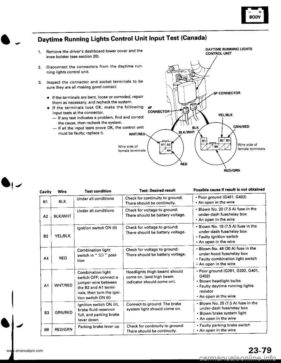
Daytime Running Lights Control Unit Input Test (Canadal
1.Remove the driver's dashboard lower cover and the
knee bolstet (see section 20).
Disconnect the connectors from the daytime run-
ning lights control unit.
Inspect the connector and socket terminals to be
sure they are all making good contact.
lf the terminals are bent, loose or corroded, repair
them as necessary, and recheck the system.
lf the terminals look OK, make the tollowing
inout tests at the connector'
- lf anv test indicates a problem, find and correct
the cause, then recheck the system.
- lf all the input tests prove OK, the control unrt
IPCONNECTOR
must be faulty; replace it.
T€st condition
DAYTIME RUNNING LIGHTS
CONTBOL UNIT
Tost: Desired result
8P CONNECTOR
YEL/BLK
GRN/RED
Possible cause ii r$uh is not obtained
BLK/WHT
Cavity
RED/GRN
B1BLKUnder all conditionsCheck for continuity to ground:
There should be continuity.
. Poor ground (G401, G402)
. An open in the wire
A2BLK,4iVHT
Under all conditionsCheck tor voltage to ground:
There should be battery voltage.
Blown No. 20 (7.5 A) luse in the
under-dash fuse/relay box
An open in the wire
82YEUBLK
lgnition switch oN (ll)Check for voltage to ground:
There should be battery voltage.
Blown No. 18 (7.5 A) fuse in the
under-dash tuse/relay box
Faulty ignition switch
An open in the wire
A4RED
Combination light
switch in " =D " Posi-
uon
Check for voltage to ground:
There should be battery voltage.
Blown No.,tg (30 A) fuse in the
under-hood fuse/relay box
Faulty combination light switch
An open in the wire
A1WHT/RED
Combination light
switch OFF; connect a
jumper wire between
the 82 and 41 termi-
nals, then turn the igni-
tion switch ON (ll)
Headlights (high beam) should
come on, (and high beam
indicator should come on).
Poor ground (G201. G202, G401,
G402)
Blown headlight bulbs
Faulty daytime running lights
resrslor
An open in the wire
R'IGRN/RED
lgnition switch ON (ll),
brake fluid reservoir
full. and parking brake
lever down
Connect to ground: The brake
system light should come on.
Blown No. 25 (7.5 A) fuse in the
under-dash fuse/relaY box
Blown brake system light
An open in the wire
B68EDlGRNParking brake lever upCheck for continuity to ground:
There should be continuity
. Faulty parking brake switch
. An open in the wire
www.emanualpro.com
Page 1246 of 1395
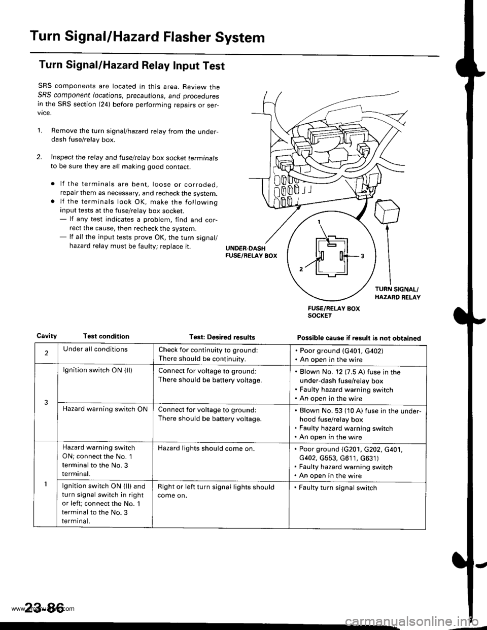
Turn SignallHazard Flasher System
Turn Signal/Hazard Relay Input Test
SRS components are located in this area. Review theSRS component /ocations, precautions, ano proceoures
in the SRS section (24) before performing repairs or ser-vice.
1.Remove the turn signal/hazard relay from the under-dash fuse/relay box.
Inspect the relay and luselrelay box socket terminals
to be sure they are all making good contact.
lf the terminals are bent, loose or corroded,reparr them as necessary, and recheck the system.lf the terminals look OK, make the following
input tests at the fuse/relay box socket.- lf any test indicates a problem, find and cor-
rect the cause, then recheck the system.- lf all the input tests prove OK, the turn signal/
hazard relay must be faulty; replace it.
CavityTest conditionTesl: Desired results
FUSE/RCLAY BOXSOCKET
Possible cause if result is not obtained
'1
IF\_-'l -]l
$ o{+-/ll ll
2Under all conditionsCheck for continuity to ground:
There should be continuity.
. Poor ground (G401, G402). An open in the wjre
3
lgnition switch ON (lllConnect for voltage to ground:
There should be battery voltage.
Blown No. 12 (7.5 A) fuse in the
under-dash fuse/relay box
Faulty hazard warning switch
An open in the wire
Hazard warning switch ONConnect for voltage to ground:
There should be battery voltage.
Blown No. 53 (10 A) fuse in the under-
hood fuse/relay box
Faulty hazard warning switch
An open in the wire
1
Hazard warning switch
ON; connect the No. 1
terminal to the No. 3
terminal.
Hazard lights should come on.Poor ground (G201. c202, c401,
G402, G553, G611, c631)
Faulty hazard warning switch
An open in the wire
lgnition switch ON (ll) and
turn signal switch in right
or left; connect the No. 'l
terminal to the No.3
terminal.
Right or left turn signal lights should
come on.
. Faulty turn signal switch
23-86
www.emanualpro.com
Page 1249 of 1395
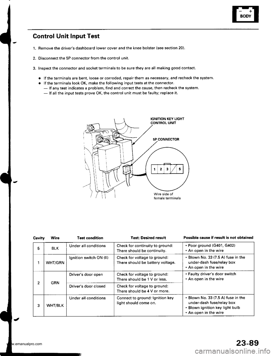
Control Unit Input Test
l. Bemove the driver's dashboard lower cover and the knee bolster (see section 20).
2, Disconnect the 5P connector from the control unit.
3. Inspect the connector and socket terminals to be sure they are all making good contact.
. lf the terminals are bent, loose orcorroded, repairthem as necessary, and recheck the system.
. lf the terminals look OK, make the following input tests at the connector.- lf any test indicates a problem, find and correct the cause. then recheck the system.
- lf all the input tests prove OK, the control unit must be faulty; replace it.
IGNITION KEY LIGHTCONTROL UNIT
5P CONNECTOR
\
))
Test conditionCavityWireTest: Desired resultPossible cause if r€sult is not obtained
BLKUnder all conditionsCheck for continuity to ground:
There should be continuity.
. Poor ground {G401, G402}. An open in the wire
'IWHT/GRN
lgnition switch ON (ll)Check for voltage to ground:
There should be battery voltage.
. Blown No. 33 (7.5 A) fuse in the
under-dash fuse/relay box. An open in the wire
GRN
Driver's door openCheck for voltage to ground:
There should be 1 V or less.
. Faulty driver's door switch. An open in the wire
Driver's door closedCheck for voltage to ground:
There should be 4 V or more.
WHT/BLK
Under all conditionsConnect to ground: lgnition key
light should come on.
Blown No. 33 (7.5 A) fuse in the
under-dash fuse/relay box
Blown ignition key light bulb
An open in the wire
23-89
www.emanualpro.com
Page 1251 of 1395
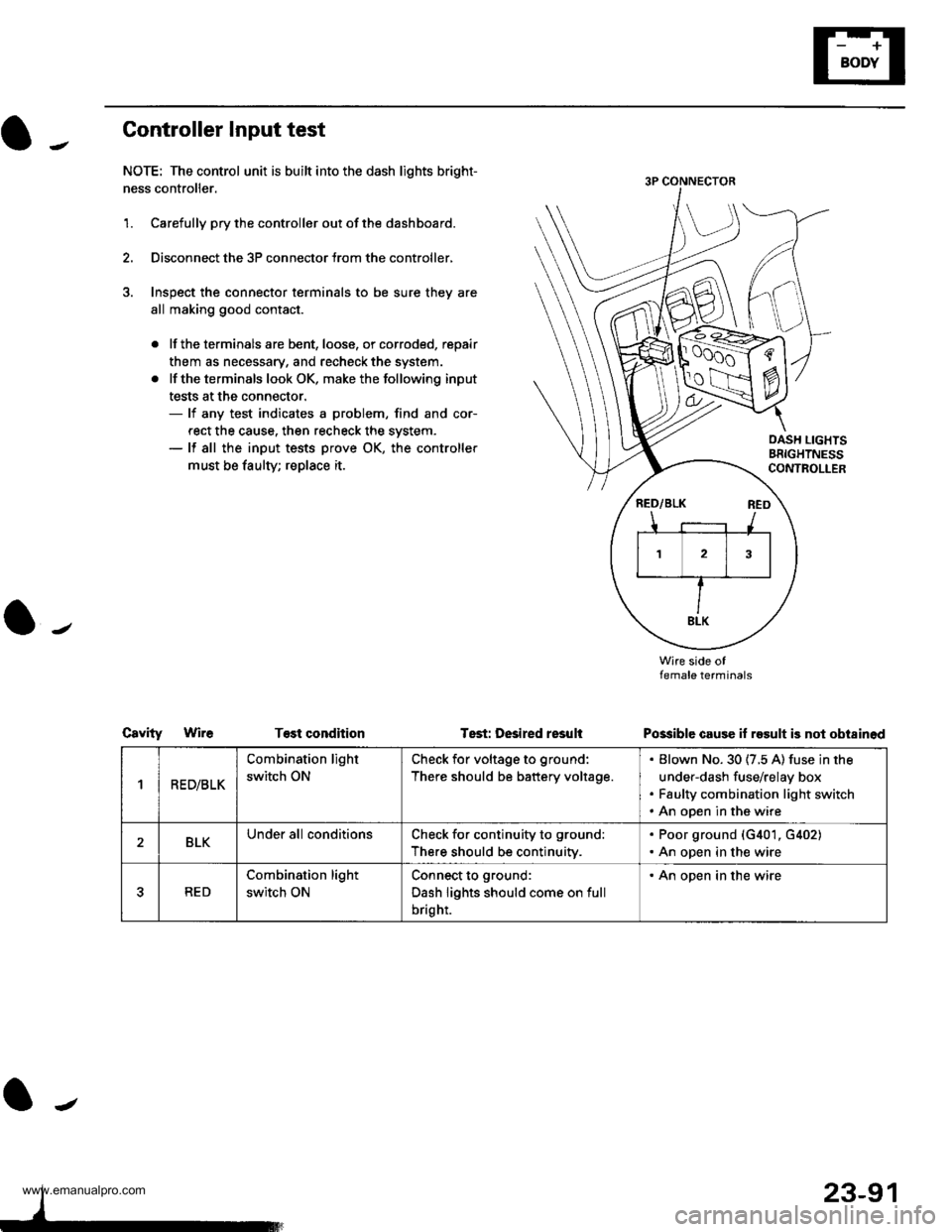
Controller Input test
NOTE: The control unit is built into the dash lights bright-
ness controller.
1.Carefully pry the controller out of the dashboard.
Disconnect the 3P connector trom the controller,
Inspect the connector terminals to be sure they are
all making good contact.
. lf the terminals are bent, loose, or corroded, repair
them as necessary, and recheck the system.
. lf the terminals look OK, make the following input
tests at the connector.- lf any test indicates a problem, find and cor-
rect the cause. then recheck the system.- lf all the input tests prove OK, the controller
must be taulty; replace it.
CsvityWireT€st condhion
Wire side oflemale terminals
Possible cause if result is not obi8inod
OASH LIGHTSBRIGHTNESSCONTROLLER
Tsst: Desired resuli
1R ED/BLK
Combination light
switch ON
Check for voltage to ground:
There should be battery voltage.
Blown No. 30 (7.5 A) fuse in the
under-dash fuse/relay box
Faulty combination light switch
An open in the wire
2BLKUnder all conditionsCheck for continuity to ground:
There should be continuitv.
. Poor ground (G401, G402). An open in the wire
5RED
Combination light
switch ON
Connect to ground:
Dash lights should come on full
bright.
. An open in the wire
23-91
www.emanualpro.com
Page 1256 of 1395
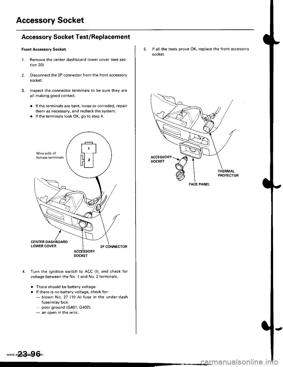
Accessory Socket
Accessory Socket Test/Replacement
Front Accessory Socket:
1. Remove the center dashboard lower cover (see sec-
tion 20).
Disconnect the 2P connector from the front accessory
socket.
Inspect the connector terminals to be sure they are
all making good contact.
2.
lf the terminals are bent, loose or corroded, repair
them as necessary, and recheck the system.
lf the terminals look OK, go to step 4.
ACCESSORYSOCKET
Turn the ignition switch to ACC (l), and check for
voltage between the No. 1 and No. 2 terminals.
. There should be battery voltage.
. lf there is no battery voltage, check for:- blown No.27 (10 A) fuse in the under-dash
fuse/relay box.- poor ground (G401, G402).- an open in the wire.
23-96
5. If all the tests prove OK, replace the front accessory
socket.
PBOTECTOB
FACE PANEL
www.emanualpro.com