Page 925 of 1395

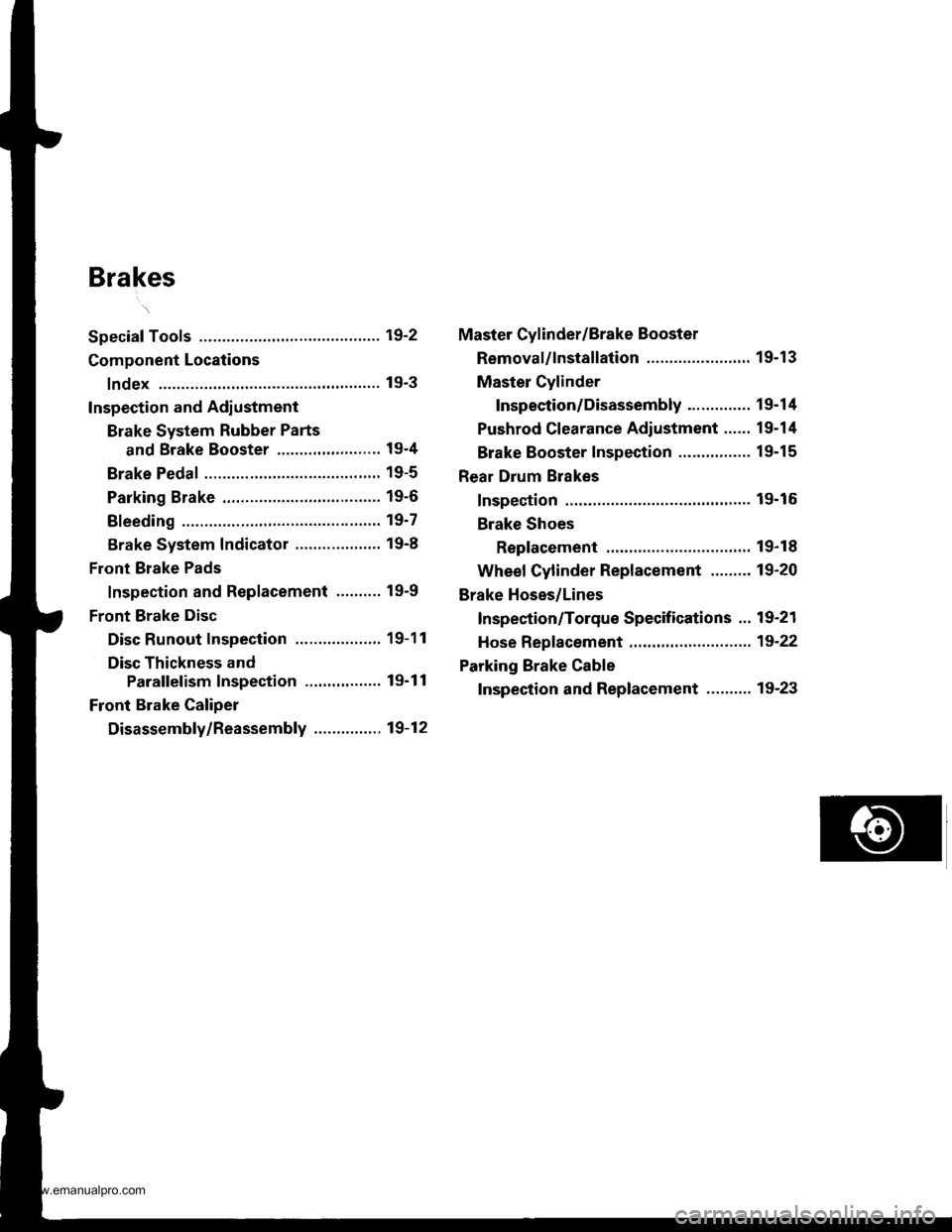
Brakes
Special Tools ............. 19-2
Component Locations
lndex ................ ...... 19-3
Inspection and Adlustment
Brake System Rubber Parts
and Brake Booster ..........,,,.......... 19-4
Brake Pedal ............ 19-5
Parking Brake ........ 19-6
Bleeding ................. 19'7
Brake System Indicator ................... 19-8
Front Brake Pads
Inspection and Replacement .......... 19-9
Front Brake Disc
Disc Runout Inspection ................... 19-11
Disc Thickness and
Parallelism Inspection ........,........ 19-1 1
Front Brake Caliper
Disassembly/Reassembly ............... 19-12
Master Cylinder/Brake Booster
Removal/lnstallation ....................... 19-13
Master Cylinder
Inspection/Disassembly .............. 19-14
Pushrod Clearance Adiustment ...... 19-14
Brake Booster Inspection ...,.,,,,....... 1 9-1 5
Rear Drum Brakes
Inspection .............. 19-15
Brake Shoes
Replacement ..... 19-r 8
Wheel Cylinder Replacement ......... 19-20
Brake Hoses/Lines
Inspection/Torque Specifications ... 19-21
Hose Replacement ....,...,............. ..,,, 19-22
Parking Brake Cable
Inspection and Replacement .......... 19-23
www.emanualpro.com
Page 927 of 1395
Gomponent Locations
lndex
ERAKE SYSTEM INOICATORCircuit Diagram, page't9-8
PARKING BRAKEAdjustment, page 19-6Parking Brake Switch Test, page '19-8
PARKING BRAKE CABI..EInspection and Replacement,page 19-23
BRAKE BOOSTERBrake Booster Inspection, page 19-15
Removal/lnstallation, page 19 13
MASTER CYLINDER
Inspection, pago 19-16Brake Shoes Replacement,page 19-18Wheel CylinderReplacement, page 19-20
REAR DRUM BRAKE
Removal/lnstallation, page 19-13lnspection/Disassembly.page 19-14Pushrod Clearance Adjustment,page 19 ldBrake Fluid LevelSwitch Test,page 19-8
Inspection/Torque Specification, pag€'19-21
Hose Replacement, Page 19-22
Front Brake Pads, page 19-9Front Brake Disc. page 19-11Front Brake Caliper, page 19-12
)i't ' -"''
/'"''t,'..,1 ...,. , \,,,.
i ,.'
'a.,
I
.) ..)
t ^fl)
19-3
www.emanualpro.com
Page 981 of 1395
Pulsers/Wheel Sensors
Wheel Sensor Replacement
NOTE;
. Be carefulwhen installing the sensors to avoid twisting the wires.
. The torque value of the bolts is 9.8 N.m ( 1.0 kgf.m, 7 Ibf.ft).
Front
6 mm BOLT9.8 N.m {1.0 kgtm. ?.2lbf'ft)
WHEEL SENSOR
Rgar
1. Remove the hub bearing unit (see section 18).
2. Remove the tour backing plate bolts.
3, Pull the backing plate away from the trailing arm, then remove the wheel sensor. lt is not necessary to disconnect the
brake line.
NOTE: This illustration shows the '97 - 98 models, The '99 - 00 models are similar.
6 mm BOLT9,8 N.m 11.0 kgf.m, 7.2lbf.ft)
\all
19-58
WHEEL SENSOR
www.emanualpro.com
Page 1391 of 1395

Cable Reel
16.
Replacement (cont'dl
11.
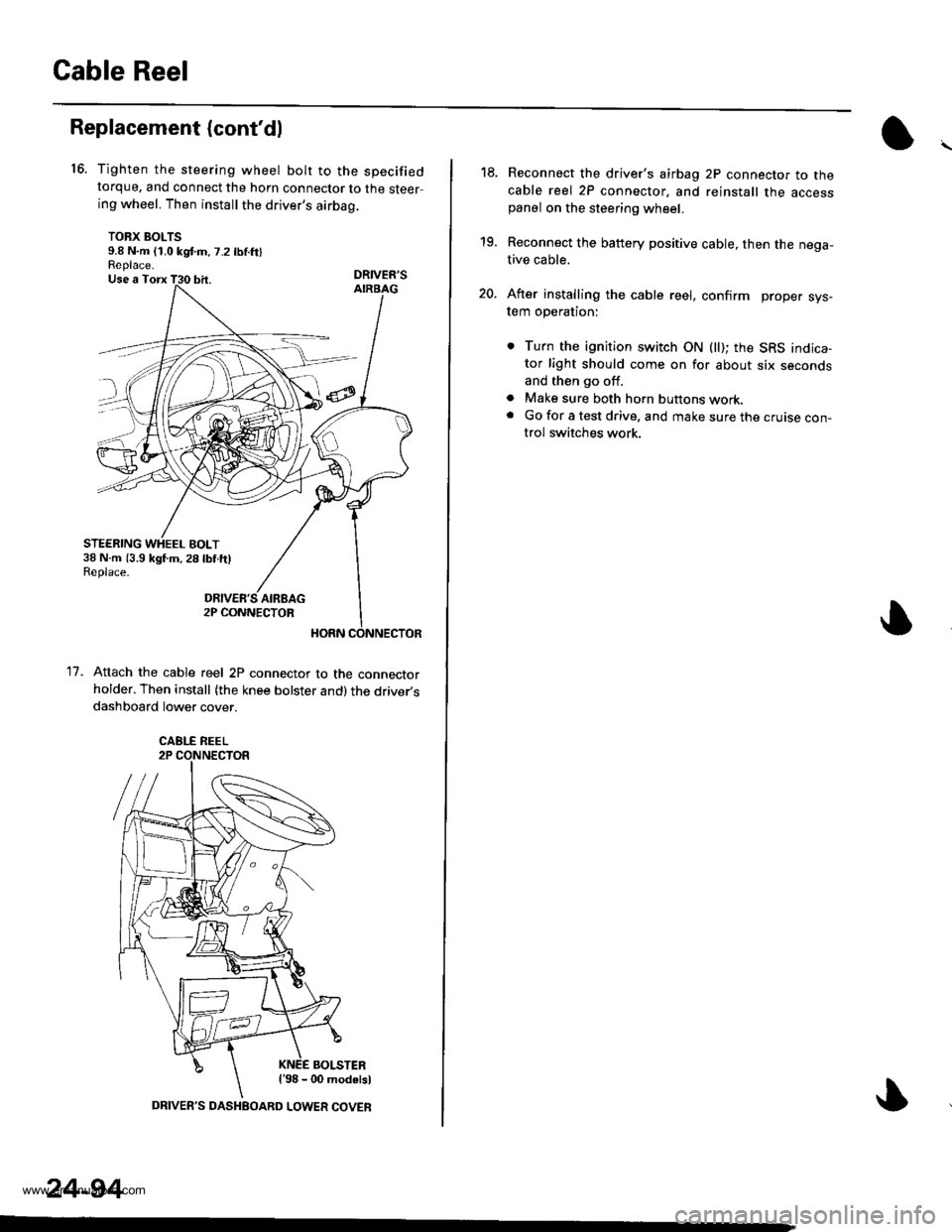
Tighten the steering wheel bolt to the specifiedtorque, and connect the horn connector to the steering wheel. Then install the driver's airbag.
TORX BOLTS9.8 N.m (1.0 kgd.m,7.2 lbnftlReplace.DRIVER'S
Attach the cable reel 2P connector to the connectorholder. Then install (the knee bolster and)the driver,sdashboard lower cover.
BOLSTERl'98 - 00 modalsl
STEERING WHEEL BOLT38 N.m (3.9 kgl.m,28lbf.ftlReplace.
CABLE REEL
24-94
DRIVER'S DASHEOARD LOWER COVER
19.
20.
Reconnect the driver's airbag 2P connector to thecable reel 2P connector, and reinstall the accesspanel on the steering wheel.
Reconnect the battery positive cable, then the nega-tive cable.
After installing the cable reel, confirm proper sys-tem operation:
. Turn the ignition switch ON (ll); the SRS indica-tor light should come on for about six secondsand then go off.
a Make sure both horn buttons work.. Go for a test drive. and make sure the cruise con-trol switches work.
www.emanualpro.com