Page 827 of 1395
Front Driveshafts
Reassembly (cont'd)
16. Unwind the boot band tool. and cut off the excess
free end of the band to leave a 5 - 10 mm (0.2 - 0.4
in) tail protruding from the clip.
5- 10 mm
10.2 - 0.4 in,
Bend the band end by tapping it down with a ham-
mer,
NOTE;
. Make sure the band does not move,
. Remove any grease remaining on the surround-
ing surfaces.
18, Install the new set ring.
17.
16-12
Outbosrd Joint Sids:
1. Wrap the splines with vinyl tape to prevent damage
to the boot.
OUTBOARD BOOT
2, Install the boot band and outboard boot, then
remove the vinyl tape. Take care not to damage the
boot.
3. Install the stop ring into the driveshaft groove.
VINYL TAPE
DRIVESHAFT
www.emanualpro.com
Page 829 of 1395
Front Driveshafts
8. Fit the boot ends onto the driveshaft and outboard
lornt.
OUTBOARD BOOT fiPE)
OUTBOARD BOOT
OUTBOARD BOOT
Reassembly (cont'd)
Install the boot bands,
. For all '97 models and'98
step 13.
. For'98 Canada models andgo to step 10.
OUTBOARD JOINT
USA models, go to
all '99 - 00 models,
10. Set the ear clamp band by threading the tab into theholes of the band.
16-14
11. Close the ear portion of the band with a commercially
available boot band pincers KENT-MOORE J-35910 or
equivalent.
BOOT BAND PINCERSKENT.MOORE J-35910or equivalent
12.Check the clearance between the closed ear Dortionof the band, lf the clearance is not within the stan-dard, close the ear portion of the band further.
6.0 mm 10.24 in) MAX
3.0 mm {0.12 in} MAX
EAR PORTION
www.emanualpro.com
Page 831 of 1395
Front Driveshafts
Reassembly (cont'dl
18.
19.
Place a wrench on the winding mandrel of the boot
band tool, and tighten the band until the marked
spot on the band meets the edge of the clip.
Lift up the boot band tool to bend the free end of
the band 90" to the clip. Center-punch the clip, then
fold over the remaining tail onto the clip.
Unwind the boot band tool. and cut off the excess
free end of the band to leave a 5 - 10 mm (0.2 - 0.4
in) tail protruding from the clip.
20.
CLIP
16-16
21, Bend the band by tapping it down with a hammer.
NOTE: Make sure the band and the clip does not
interfere with anything, and the band does not
move, Remove any grease remaining on the sur-
rounding surfaces.
BAND END
www.emanualpro.com
Page 832 of 1395

Front Driveshafts
lnstallation
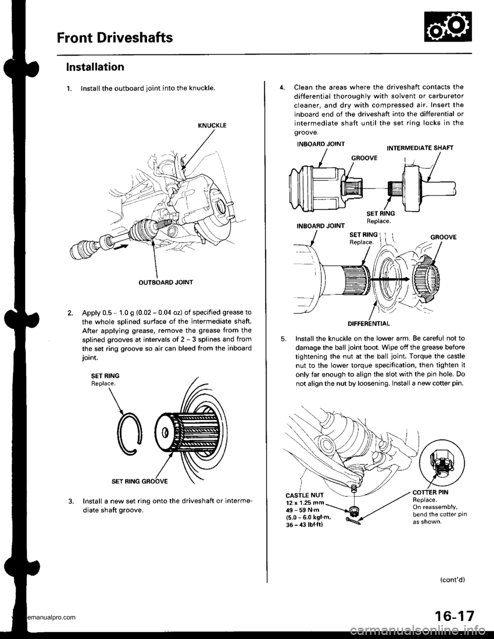
1. Install the outboard ioint into the knuckle.
KNUCKLE
OUTBOARD JOINT
Apply 0.5 - 1.0 g (0,02 - 0.04 oz) of specified grease to
the whole sDlined surface of the intermediate shaft.
After applying grease. remove the grease from the
splined grooves at intervals of 2 - 3 splines and from
the set ring groove so air can bleed from the inboard
ioint.
SET RINGReplace.
SET RING
Install a new set ring onto the driveshaft or interme-
diate shaft groove.
4. Clean the areas where the driveshaft contacts the
differential thoroughly with solvent or carburetor
cleaner, and dry with compressed air. Insert the
inboard end of the driveshaft into the differential or
intermediate shaft until the set ring locks in the
groove.
INBOARD JOINT
INBOARD JOINT
lnstall the knuckle on the lower arm. Be careful not to
damage the ball joint boot. Wipe off the grease before
tightening the nut at the ball joint. Torque the castle
nut to the lower torque specification. then tighten it
only far enough to align the slot with the pin hole. Do
not align the nut by loosening. lnstall a new cotter pin.
5.
CASTLE NUT12 x 1 .25 mm49-59Nm(5.0 - 6.0 kgl'm,36 - 4:l lbl.ft)
COTTER PINReplace.On reassembly,bend the cotter pin
(cont'd)
16-17
Replace.
www.emanualpro.com
Page 833 of 1395

Front DriveshaftsIntermediate Shaft
Installation {cont'd}
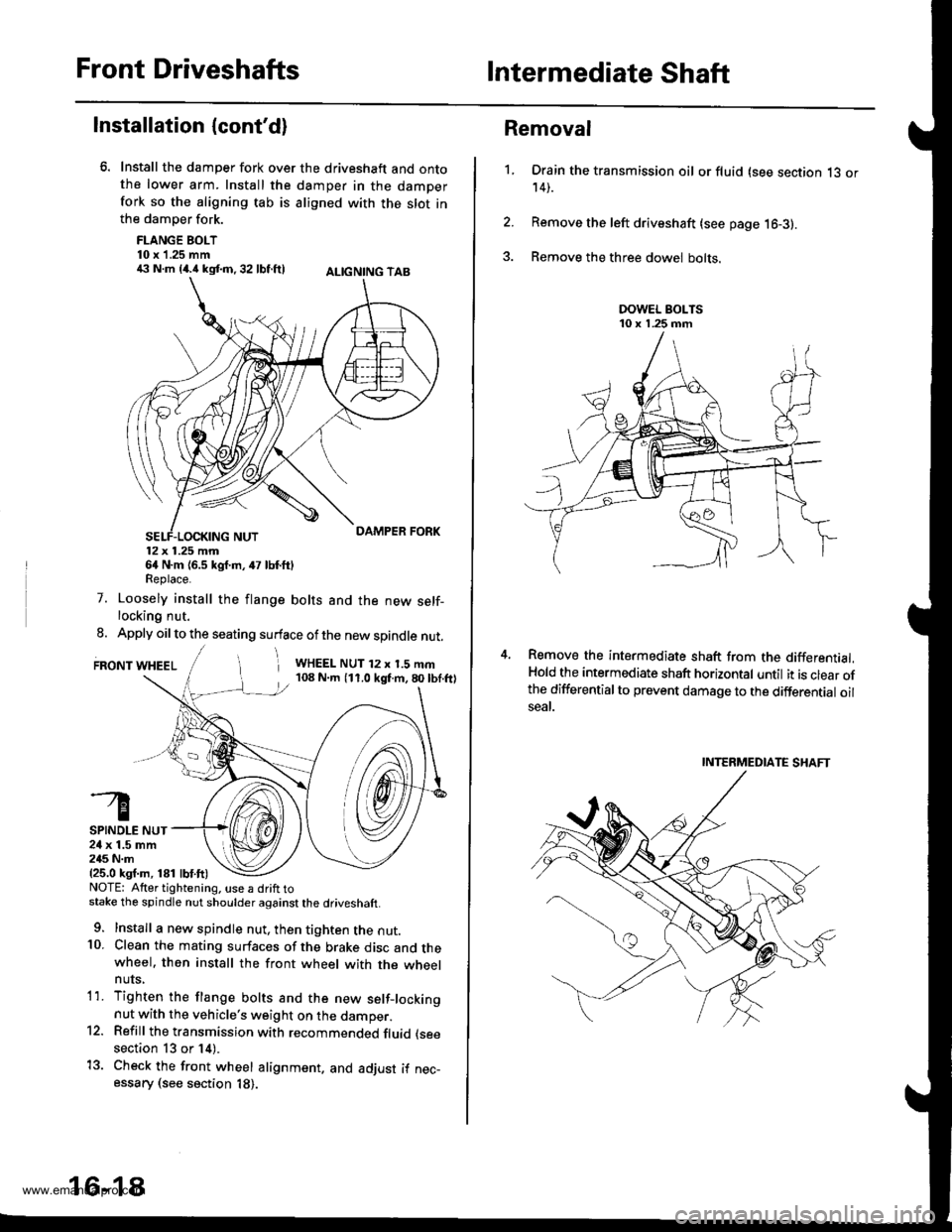
Install the damper fork over the driveshaft and ontothe lower arm. Install the damper in the damperfork so the aligning tab is aligned with the slot inthe damper fork.
FLANGE BOLT10 x 1.25 mm€ N.m {4.i1kst.n,32 lbf.ftl ALtcNtNG TAB
12x 1.25 mm64 N.m {6.5 kgf.m, 47 lbf.ftlReplace.
7. Loosely install the flange bolts and the new self-locking nut.
8. Apply oil to the seating surface of the new spindle nut.
FRONT WHEELi WHEEL NUT 12 x 1.5 mm108 N.m (11.0 kgf.m,80lbf.ftl
SPINDLE NUT24 x 1.5 mm245 N.m{25.0 ksf.m, 181 lbf.ft)NOTE: Atter tightening. use a drift tostake the spindle nut shoulder against the driveshaft.
9. Install a new spindle nut, then tighten the nut.10. Clean the mating surfaces of the brake disc and thewheel. then install the front wheel with the wheelnuts,
1'1. Tighten the flange bolts and the new setf-lockingnut with the vehicle's weight on the damper.12. Refill the transmission with recommended fluid (see
section 13 or 14).
13. Check the front wheel alignment. and adjust if nec-essary (see section 18).
16-18
1.
Removal
Drain the transmission oil or fluid (see section 13 or14).
Remove the left driveshaft (see page 16-3).
Remove the three dowel bolts.
Remove the intermediate shaft from the differential.Hold the intermediate shaft horizontal until it is clear ofthe differentialto prevent damage to the differential oilseal.
INTERMEDIATE SHAFT
www.emanualpro.com
Page 841 of 1395
Rear Driveshafts
Reassembly (cont'd)
8. Install the joint by holdjng the driveshaft straight upand aligning the marks on the joint with the marks
on the rollers,
9.Adjust the position of the joints to the specificationsshown. then adjust the boots halfway between fullcompression and full extension. Make sure the endsof the boots are seated in the grooves in the joints.
Inboard ioint l€ngth:
153 - 157 mm {6.02 - 6.18 inl
Outboard ioint l6ngth:
l/l:' - 147 mm {5.63 - 5.37 in}
16-26
10. Set the double loop band onto the boot with theband end toward the front of the vehicle,
Pull up the slack in the band by hand.
Make a mark on the band 10 - 14 mm (0.4 - 0.6 in)from the clip.
11.
12.
CLIP
www.emanualpro.com
Page 846 of 1395

Steering
Special Toofs ............. 17-2
Component Locations
Index ................ ....... 17-3
Troubleshooting
General Troubleshooting ................ 1 7-4
Noise and Vibration ......................... 17-8
Fluid Leaks ............. 17-10
Inspection and Adiustment
Steering Operation .......................... 17-12
Power Assist Check
With Vehicle Parked ....................
Steering Linkage and Gearbox .......
Pump Belt
Rack Guide Adjustment ...................
Fluid Rep|acement ...................,,.,....
Pump Pressure Check .................,,...
*Steering Wheel
Removal ................. 17-18
*Steering Column
Removal/lnstallation ................ ....... 17 -2O
lnspection .............. 17-21
Steering Lock Replacement ............ 17 -22
Power Steering Hoses, Lines
Ffuid Leakage Inspection ................. 17 -23
Repfacement .......... 17-23
Power Steering Pump
Repfacement .......... 17-24
Disassembly ...........17-25
fnspection .............. 17-26
Reassembly ............ 17-28
Power Steering Gearbox
Removal ................. 17-31
Disassembly ........... 17-34
Reassembly ............ 17-40
Ball Joint Boot Replacement .......... 17-50
Installation ............. 17-51
17-12
17-13
17-14
l7-15
17-15
17-16
Disassembly/Reassembly............... 17-18
4'%/b.......... -r'-7--a/
SUPPLEN\EN AL RES\RA(N SYSTES{ (SRS\
This model has an SRS which includes a driver's airbag in the steering wheel hub. a passenger's airbag in the dashboardabove the glove box ('97 - 00 models), and seat belt tensioners in the seat belt retractors ('98 - 00 models). Informationnecessary to safely service the SRS is included in this Service Manual. ltems marked with an asterisk (*) on the contentspage include, or are located near, SBS components. Servicing. disassembling or replacing these items will require specialprecautions and tools, and should only be done by an authorized Honda oearer.
To avoid rendering the SRS inoperative, which could lead to peFonal iniury or death in the event of a sevore trontalcollision. allSRS service work must be performod by an authorized Honda dealer.lmproper service procedurgs, including incorrect removal and installalion of the SRS, could lead to personal iniurycaused by unintontional deployment of th€ airbags {'97 - 00 models), and seat belt tensioners ('98 - 00 modelsl.Do not bump the SRS unit. Otherwise, the system may lail in case ot a collision, or the airbags may deploy when theignition switch is ON (lll.
SRS electrical wiring harnesses are identitied by yellow colof coding. Ralated components are located in the steeringcolumn, front console, dashboard, dashboard lower panel, and in the dashboard above the glove box. Do not use elec-trical test equipment on these cilcuits,
www.emanualpro.com
Page 876 of 1395

Power Steering Gearbox
Removal
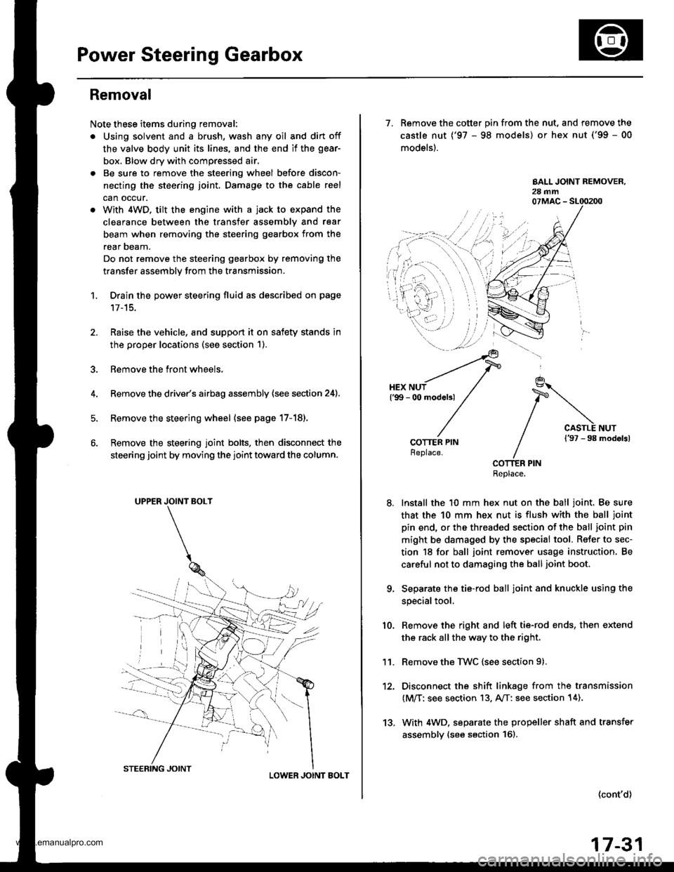
Note these items during removal:
. Using solvent and a brush, wash any oil and dirt off
the valve body unit its lines, and the end if the gear-
box. Blow dry with compressed air.
. Be sure to remove the steering wheel before discon-
necting the steering joint. Damage to the cable reel
can occur.
. With 4WD. tilt the engine with a jack to expand the
clearance between the transfer assembly and rear
beam when removing the steering gearbox from the
rear oeam.
Do not remove the steering gearbox by removing the
transfer assembly from the transmission.
1. Drain the power steering fluid as described on page'17-15.
Raise the vehicle, and suppon it on safety stands in
the proper locations (see section 1).
Remove the front wheels,
Remove the drive/s airbag assembly {see section 24).
Remove the steering wheel {see page 17-18).
Remove the steering joint bolts, then disconnect the
steering joint by moving the joint toward the column.
UPPER JOINT BOLT
LOWER JOINT BOLT
13.
7. Remove the cotter pin from the nut, and remove the
castle nut {'97 - 98 models) or hex nut ('99 - 00
models).
COTTER PINReplace.
Install the 10 mm hex nut on the ball joint. Be sure
that the 10 mm hex nut is flush with the ball joint
pin end, or the threaded section of the ball joint pin
might be damaged by the special tool. Refer to sec-
tion 18 for ball joint remover usage instruction, Be
careful not to damaging the ball joint boot.
Separate the tie-rod ball joint and knuckle using the
special tool.
Remove the right and left tie-rod ends, then extend
the rack all the way to the right.
Remove the TWC (see section 9).
Disconnect the shift linkage from the transmission
(M/T: see section 13, A/T: see section 14).
With 4WD. separate the propeller shaft and transfer
assembly (see section 161.
10.
11.
(cont'd)
17-31
www.emanualpro.com