1999 HONDA CR-V alignment
[x] Cancel search: alignmentPage 913 of 1395
'1.
Lower Ball Joint Replacement
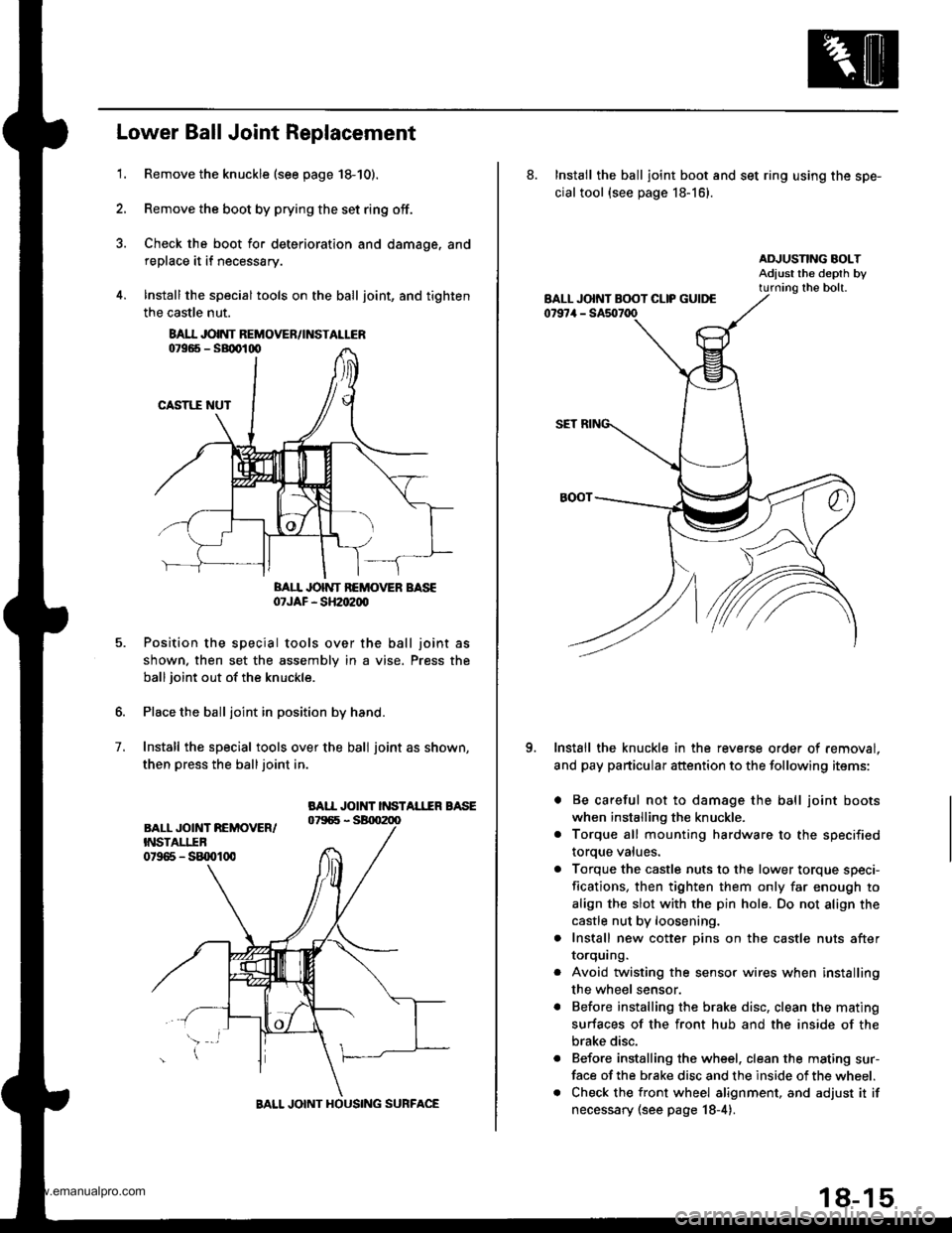
Remove the knuckle (see page 18-10).
Remove the boot by prying the set ring off.
Check the boot for deterioration and damage. and
replace it if necessary.
lnstall the special tools on the ball joint, and tighten
the castle nut.
BAII JOINT BEMOVER BASE07JAF - SH2oe00
Position the special tools over the ball joint as
shown. then set the assembly in a vise. Press the
ball joint out of the knuckle.
Place the ball joint in position by hand.
Install the special tools over the ball joint as shown,
then press the balljoint in.
BAII JOINT INSTAL1IR BASE
7.
8AI.I JOINT REMOVEN/INSTALLER
BALL JOINT HOUSING SURFACE
18-15
8. Install the ball joint boot and set ring using the spe-
cial tool {see page 18-16}.
Install the knuckle in the reverse order of removal.
and pay particular attention to the following items:
. Be careful not to damage the ball joint boots
when installing the knuckle.
. Torque all mounting hardware to the specified
toroue values.
a Torque the castle nuts to the lower torque speci-
fications, then tighten them only far enough to
align the slot with the pin hole. Do not align the
castle nut by loosening.
. Install new cotter pins on the castle nuts after
IOrqurng.
Avoid twisting the sensor wires when installing
the wheel sensor.
Before installing the brake disc, clean the mating
surfaces of the front hub and the inside of the
brake disc.
Before installing the wheel. clean the mating sur-
face of the brake disc and the inside of the wheel.
Check the front wheel alignment, and adjust it if
necessary (see page 18-4).
o
www.emanualpro.com
Page 920 of 1395
Rear Suspension
Hub Bearing Unit Replacement (cont'd)
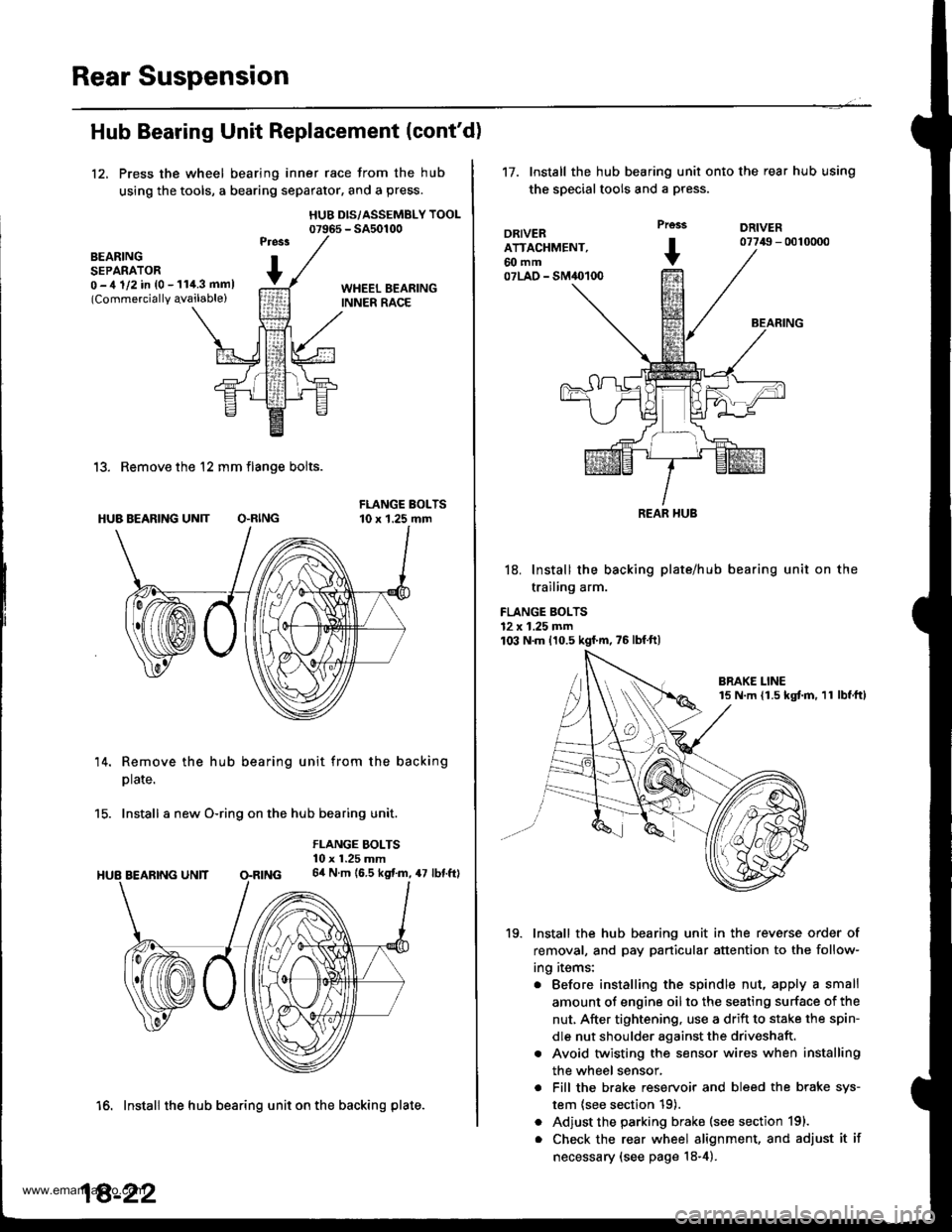
12, Press the wheel bearing inner race from the hub
using the tools, a bearing separator, and a press.
HUB DIS/ASSEMBLY TOOL07965 - SA50100
BEARINGSEPARATOR0 -,t 1/2 in {0 - 11i1.3 mml(Commercially qvailable)
13. Remove the 12 mm flange bolts.
HUB BEARING UN]T O.RING
14. Remove the hub bearing unit from the backing
plate.
15. Install a new O-ring on the hub bearing unit.
FLANGE BOLTS10 x 1.25 mm64 N.m (6.5 kgf.m, 47 lbf.ftl
16. Install the hub bearing unit on the backing plate.
18-22
't7.Install the hub bearing unit onto the rear hub using
the special tools and a press.
DRIVERATTACHMENT,60 mm07LAO - SM40100
Prcss
+
DRIVER07749 - 0010000
BEARING
18. Install the backing plate/hub
trailing arm.
FLANGE BOLTS12 x 1.25 mm103 N.m 110.5 kgf'm,75lbfft)
bearing unit on the
19. Install the hub bearing unit in the reverse order of
removal, and pay particular attention to the follow-
ing items:
. Before installing the spindle nut, apply a small
amount of engine oil to the seating surface of the
nut, After tightening, use a drift to stake the spin-
dle nut shoulder against the driveshaft.
. Avoid twisting the sensor wires when installing
the wheel sensor,
. Fill the brake reservoir and bleed the brake sys-
tem {see section 19).
. Adjust the parking brake (see section 191.
. Check the rear wheel alignment, and adjust it if
necessary (see page 18-4).
REAR HUB
www.emanualpro.com
Page 923 of 1395
Reassembly
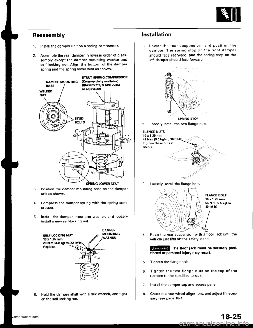
1.Install the damper unit on a spring compressor,
Assemble the rear damper in reverse order of disas-
sembly except the damper mounting washer and
self-locking nut. Align the bottom of the damper
spring and the spring lower seat as shown.
2.
DAMPER MOUNNNG
STRUT SPBING COMPRESSOR:(Commorcislly !v.ilablelBRANICKC T/N MST.s8OA
3.Position the damper mounting base on the damper
unit as shown.
Compress the damper spring with the spring com-
pressor.
Install the damper mounting washer, and loosely
install a new self-locking nut.
SELF.LOCKING NUT10 x 1.25 mm29 N.m (3.0
Replace.
Hold the damper shaft with a hex wrench, and tight-
en the self-locking nut.
1.
lnstallation
Lower the rear suspenston,
damper. The spring stop on
should face rearward, and the
left damper should face forward.
and position the
the right damper
sprang stop on the
SPRING STOP
2. Loosely install the two flange nuts.
FLANGE NUTS10 x 1.25 mm . .:{9 N.m 15.0 kgf.m, 36 lbtft}- :',,-rigf't"n if'"""_nrr. in ----.-*
qla^ 7Step 7.
3. Loosely install the flange bolt.
FLANGE EOLT10 x 1.25 mm54 N.m 15.5 kgt.m,40 tbI.ft)
6.
7.
8.
Raise the rear suspension with a floor jack until the
vehicle just lifts off the safety stand.
@ The floor iack must be securely posi-
iioned or personal iniury may result.
Tighten the flange bolt.
Tighten the two flange nuts on the top of the
damper to the specified torque.
Install the damper cap and access panel.
Check the rear wheel alignment. and adjust if neces-
sary (see page 18-4).
18-25
www.emanualpro.com
Page 1012 of 1395
7.
8.
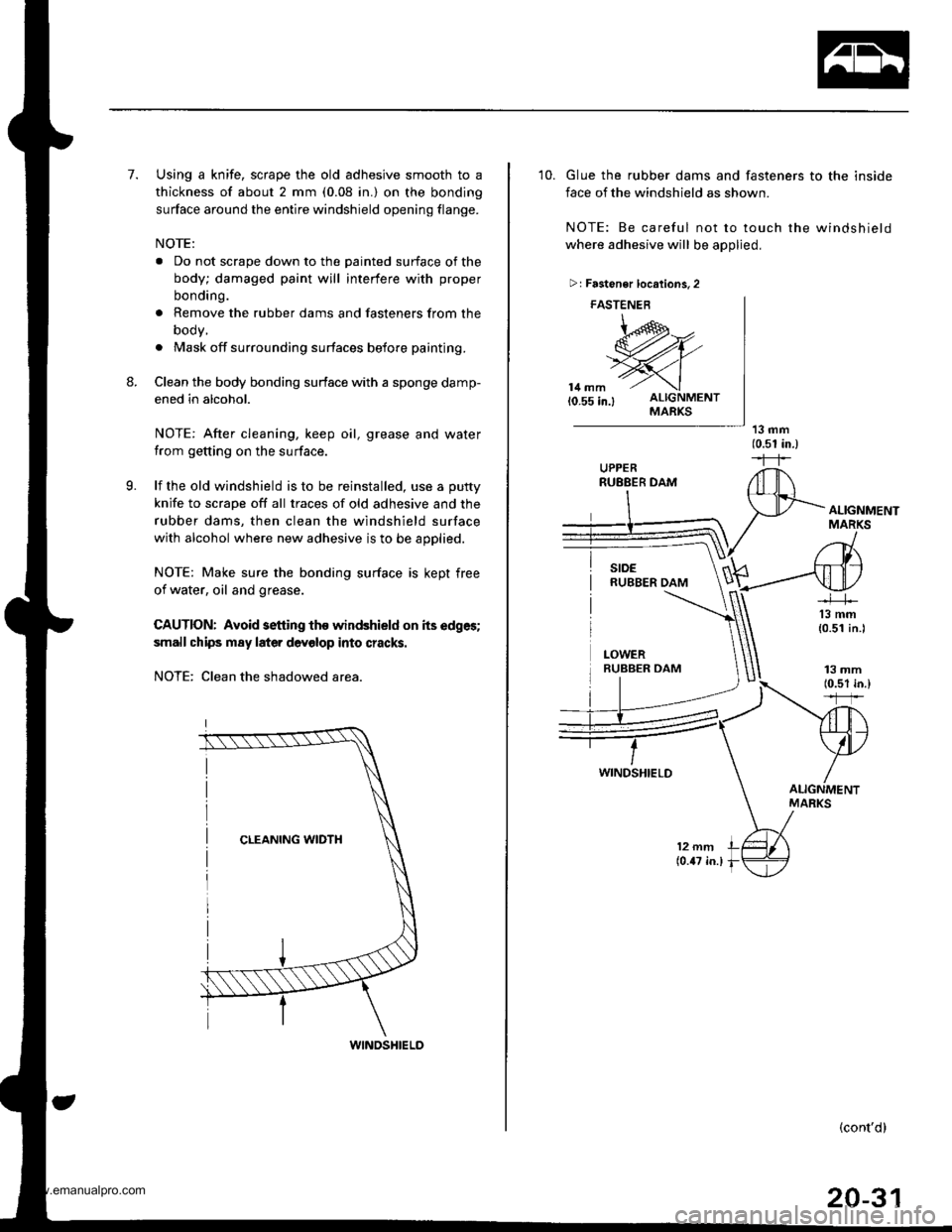
Using a knife, scrape the old adhesive smooth to a
thickness of about 2 mm (0.08 in.) on the bonding
surface around the entire windshield opening flange.
NOTE:
a Do not scrape down to the painted surface of the
body; damaged paint will interfere with proper
bonding.
. Remove the rubber dams and fasteners from the
oooy,
. Mask off surrounding surfaces before painting.
Clean the body bonding surface with a sponge damp-
ened in alcohol.
NOTE: After cleaning, keep oil, grease and water
from getting on the surface.
lf the old windshield is to be reinstalled, use a putty
knjfe to scrape off all traces of old adhesive and the
rubber dams, then clean the windshield surface
with alcohol where new adhesive is to be applied.
NOTE: Make sure the bonding surface is kept free
of water, oil and grease.
CAUTION: Avoid setting tho windshield on its edges;
small chips m8y later devolop into cracks.
NOTE: Clean the shadowed area.
9.
WINDSHIELD
10. Glue the rubber dams and fasteners to the inside
face of the windshield as shown
NOTE: Be careful not to touch the windshield
where adhesive will be applied,
13 mm(0.51 in.)--r-r
>r Fastener locrtions. 2
FASTENEB
\,@,--
w,{,.'>Yl
14 mm -'- \l0.55 in.l ALIGNMENTMARKS
ALIGNMENTMARKS
13 mm(0.51 in.l
13 mm10.51 in.)*ffi
ALIGNMENTMARKS
12 mm(0.47 in.l
(cont'd)
20-31
www.emanualpro.com
Page 1013 of 1395
Glass
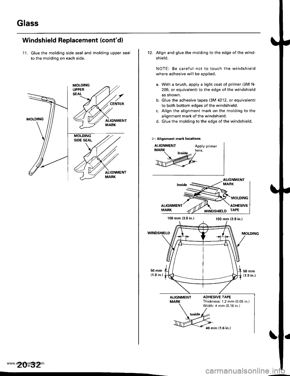
Windshield Replacement (cont'dl
11. Glue the molding side seal and molding upper seal
to the molding on each side.
20-32
12. Align and glue the molding to the edge of the wind-
shield.
NOTE: Be careful not to touch the windshield
where adhesive will be applied.
a. With a brush, apply a light coat of primer (3lvl N-
200, or equivalent) to the edge ot the windshield
as shown,
b. Glue the adhesive tapes l3M 4212, or equivalent)
to both bottom edges of the windshield.
c. Align the alignment mark on the molding to the
alignment mark of the windshield.
d. Glue the molding to the edge of the windshield.
>: Alignment mark locations
ALIGNMENTApply primerMARK here. ln3ide , /
@
100 mm {3.9 in.l100 mm {3.9 in.}
ADHESIVE TAPEThic*ness: 1.2 mm (0.05 in.)Widthr 4 mm (0.16 in.)
r0 mm (1.6 in.l
www.emanualpro.com
Page 1014 of 1395
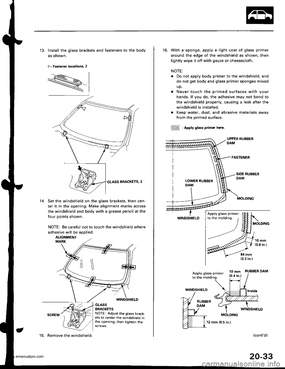
'13. Install the glass brackets and fasteners to the body
as shown.
>: Fastener locations, 2
R-
14. Set the windshield on the glass brackets. then cen
ter it in the opening. Make alignment marks across
the windshield and body with a grease pencil at the
four points shown.
NOTE| Be careful not to touch the windshield where
adhesive will be applied.
ALIGNMENTMABK
WINDSHIELD
GLASSBRACKETSNOTE: Adjust the glass brack-ets to center the windshield inthe opening, then tighten the
15. Remove the windshield.
12 mm 10.5 in.)
16. With a sponge, apply a light coat of glass primer
around the edge of the windshield as shown, then
lightly wipe it off with gauze or cheesecloth.
NOTE:
Do not apply body primer to the windshield, and
do not get body and glass primer sponges mixed
up.
Never touch the primed surfaces with your
hands. lf you do, the adhesive may not bond to
the windshield properly, causing a leak after the
windshield is installed.
. Keep water, dust, and abrasive materials away
from the primed surface.
//fu : Apply glass ptimar hea.
WINDSHIELD
10 mm{0.4 in.}RUBBER DAMApply glass primerto the molding.
(cont'd)
20-33
Apply glass primer
WINDSHIELD
MOLDING
www.emanualpro.com
Page 1016 of 1395
22.
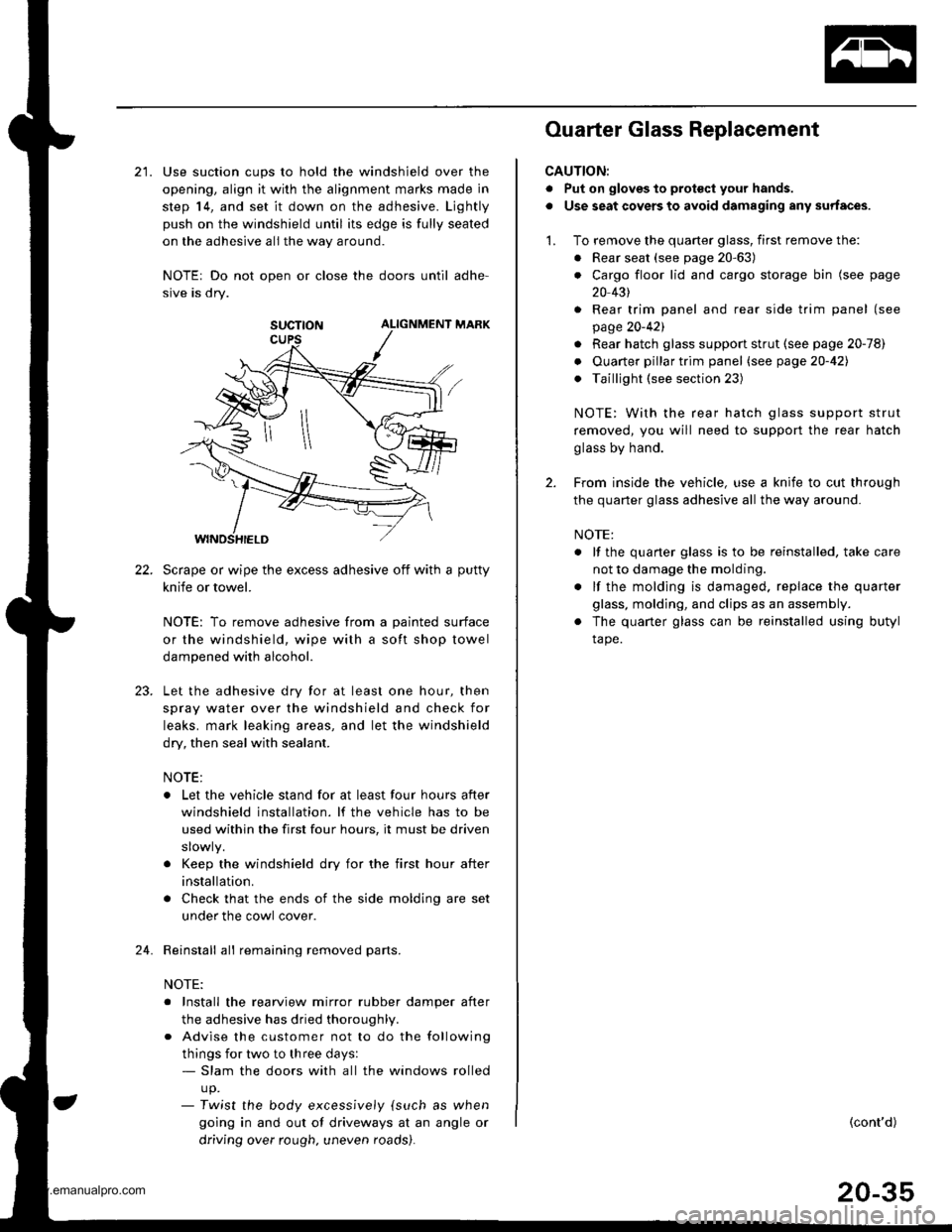
21. Use suction cups to hold the windshield over the
opening, align it with the alignment marks made in
step 14, and set it down on the adhesive. Ljghtly
push on the windshield until its edge is fully seated
on the adhesive all the way around.
NOTEr Do not open or close the doors until adhe-
sive is dry.
SUCTTON ALIGNMENT MARK
Scrape or wipe the excess adhesive off with a putty
knife or towel.
NOTE: To remove adhesive from a painted surface
or the windshield, wipe with a soft shop towel
dampened with alcohol.
Let the adhesive dry for at least one hour, then
spray water over the windshield and check for
leaks. mark leaking areas, and let the windshield
dry, then seal with sealant.
NOTE:
. Let the vehicle stand for at least four hours after
windshield installation. lf the vehicle has to be
used within the first four hours, it must be driven
. Keep the windshield dry for the first hour after
installation.
. Check that the ends of the side molding are set
under the cowl cover.
Reinstall all remaining removed parts.
NOTE:
. Install the rearview mirror rubber damper after
the adhesive has dried thoroughl,.
. Advise the customer not to do the following
things for two to three days:- Slam the doors with all the windows rolled
up.- Twist the body excess,vely {such as when
going in and out of driveways at an angle or
driving over rough. uneven roads).
24.
Ouarter Glass Replacement
CAUTION:
. Put on gloves to prot€ct your hands.
. Use seat covers to avoid damaging any surfaces.
1. To remove the quarter glass, first remove the:
. Rear seat (see page 20-63)
. Cargo floor lid and cargo storage bin (see page
20 431
. Rear trim panel and rear side trim panel (see
page 20-421
. Rear hatch glass support strut (see page 20-78)
. Ouarter pillar trim panel (see page20-421
. Taillight (see section 23)
NOTE: With the rear hatch glass support strut
removed, you will need to support the rear hatch
glass by hand.
2. From inside the vehicle, use a knife to cut through
the quarter glass adhesive all the way around.
NOTE:
. lf the quaner glass is to be reinstalled, take care
not to damage the molding.
. lf the molding is damaged. replace the quarter
glass, molding, and clips as an assembly.
. The quarter glass can be reinstalled using butyl
tape.
(cont'd)
20-35
www.emanualpro.com
Page 1018 of 1395
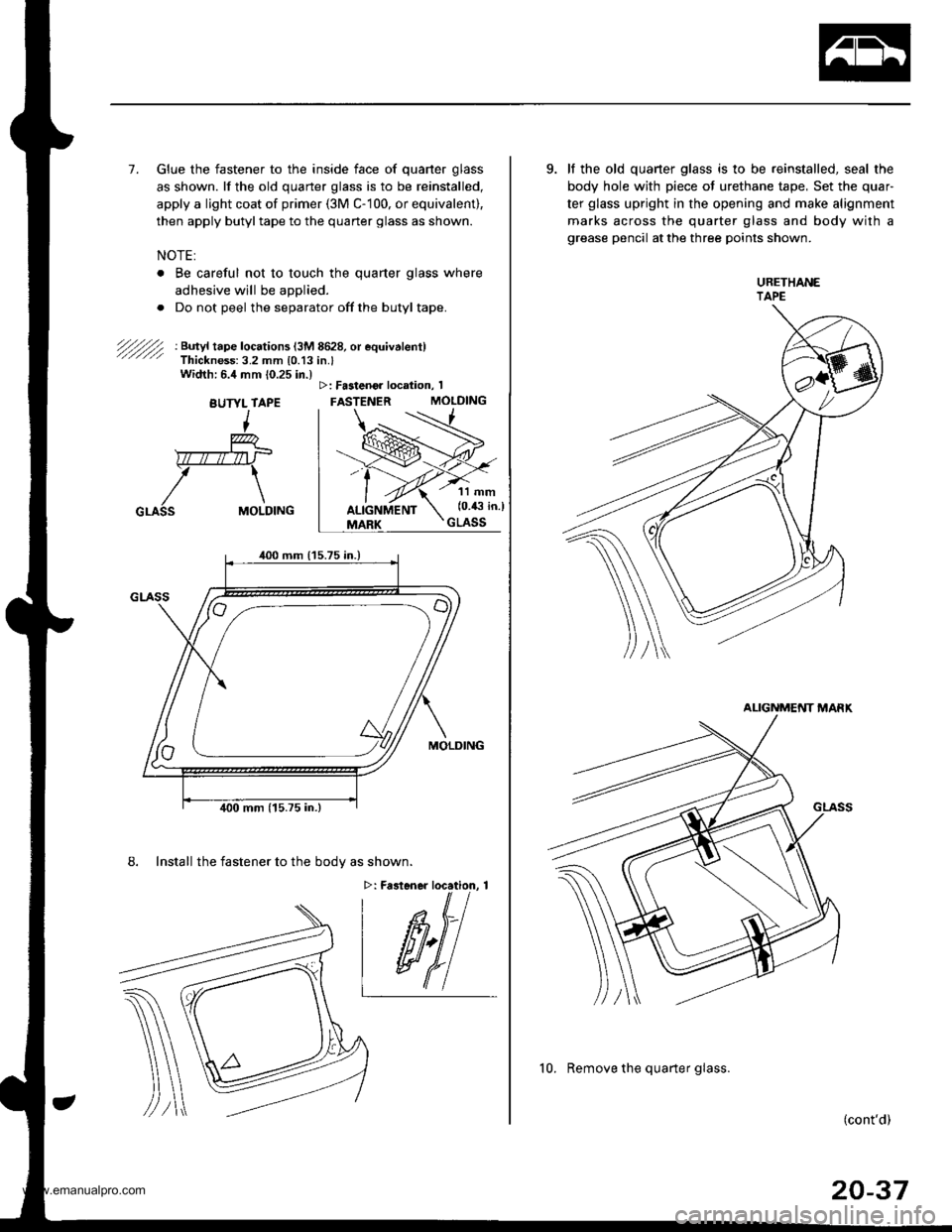
7. Glue the fastener to the inside face of quarter glass
as shown. lf the old quarter glass is to be reinstalled,
apply a light coat of primer (3M C- 100, or equivalent),
then apply butyltape to the quaner glass as shown.
NOTE:
. Be careful not to touch the quarter glass where
adhesive will be aDplied.
. Do not peel the separator off the butyl tape.
Width: 5.4 mm 10.25 in.)
BUTYL TAPE
I
w-mr
>t\
/\SS MOLDING
/'/.//// | Bttryl taee locations l3M 8628, or equivalent)Thickness:3.2 mm 10.13 in.l
>: Fastenoa location, I
FASTENER MOLDING
GLA
8. lnstall the fastener to the bodv as shown.
>: Fastener location, 1
1l mm(0.43 in.)
GLASS
400 mm (15.75 in.)
9. lf the old quarter glass is to be reinstalled, seal the
body hole with piece of urethane tape, Set the quar
ter glass upright in the opening and make alignment
marks across the quarter glass and body with a
grease pencil at the three points shown.
(cont'd)
20-37
ALIGNMENT MANK
10. Remove the quarter glass.
www.emanualpro.com