Page 143 of 1395

Cylinder Head
Installation
Installthe cylinder head in the reverse order of removal:
1. Clean the cylinder head and block surfaces.
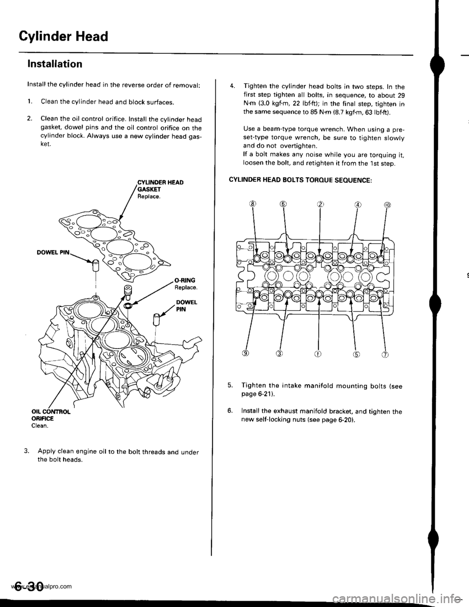
2. Clean the oil control orifice. Install the cylinder headgasket, dowel pins and the oil control orifice on thecylinder block. Always use a new cylinder head gas-ket.
CYLII{DER HEADGASKETR€place.
DOWEL PIN
O.RINGRoplace.
DOWELPIN
OIL CONTBOLORIFICEClean.
Apply clean engine oil to the bolt threads and underthe bolt heads.
4. Tighten the cylinder head bolts in two steps. In thefirst step tighten all bolts, in sequence, to about 29
N.m {3.0 kgf.m,22 lbf.ft); in the finat step, tighten inthe same sequence to 85 N.m (8.7 kgf.m,63 lbf.ft).
Use a beam-type torque wrench. When using a pre-
set-type torque wrench, be sure to tighten slowly
and do not overtighten.
lf a bolt makes any noise while you are torquing it,loosen the bolt, and retighten it from the 1st step.
CYLINDER HEAD BOLTS TOROUE SEOUENCE:
Tighten the intake manifold mounting bolts (see
page 6-21).
Install the exhaust manifold bracket. and tighten thenew self-locking nuts (see page 6-20).
6-30
www.emanualpro.com
Page 149 of 1395

lllustrated lndex
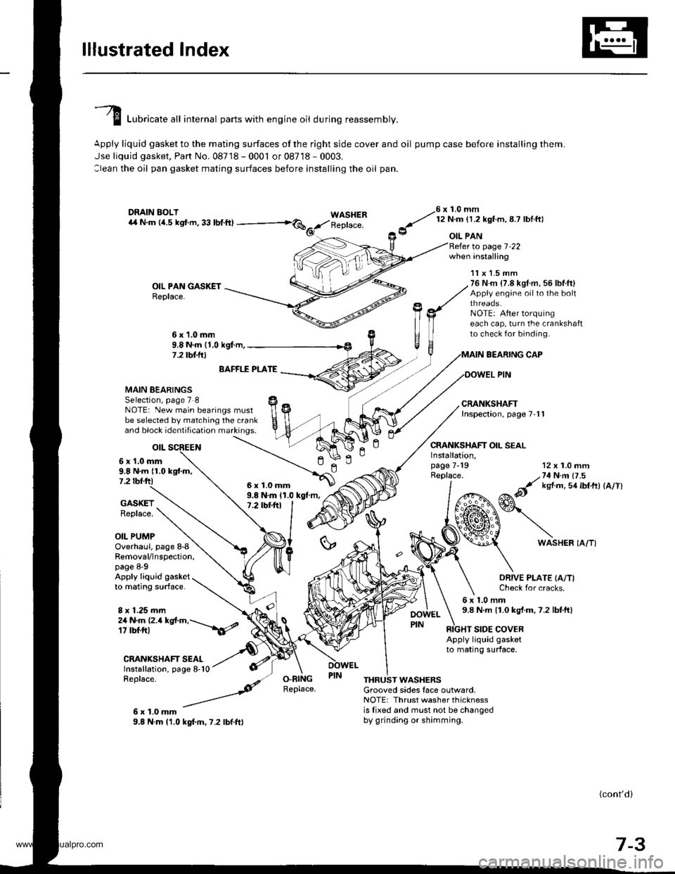
I Luori""t" "tl internal parts with engine oil during reassembly.
Apply liquid gasket to the mating surfaces of the right side cover and oil pump case before installing them.
Jse liquid gasket, Part No. 08718 - 0001 or 08718 - 0003.
:lean the oil pan gasket mating surfaces before installing the oil pan.
WASHERReplace.
76 x 1.0 mm
y' t:n- l.zxstm, 8.7 lbl ftl
9 oIL PAN
OIL PAN GASKETReplace.
to page 1-22when installing
BEARING CAP
OOWEL PIN
CRANKSHAFT OIL SEAL
11x 1.5 mm76 N.m {7.8 kgl.m, 56 lbf.ft}Appiy engine oilto the boltthreaos.NOTE: After lorquingeach cap, turn the crankshaftto check for binding.6x1.0mm9,8 N.m (1,0 kgf.m,7 .2 tbt.lrl
n
MAIN BEARINGSSelection, page 7 8NOTE: New main bearings mustbe selected by matching the crankand block identification markings.
otL
6 x'1.0 mm9.8 N.m {1.0 kgtm,7.2 tbf.ftl
BAFFI.f PLATE
9.8 N.m 11.0 kgt m,7.2 tbt+tl
12 x 1.0 mm
/,71N n 17 .5
&it ks{ m 5a lbtft) {a/Tl
GASKETReplace.
OIL PUMP
Installation,page 7-19Replace.
ln
6WASHER IA/T}Overhaul, page 8-8Removal/lnspection,page 8-9Apply liquid gasketto mating surface.
8 x 1.25 mm
ORIVE PLATE IA/T)Check for cracks.
6x1.0mm9.8 N.m 11.0 kgt.m,7.2 lbtft)2a N.m (2.a kgt.m,---\6/
CRANIGHAFT SEALInstallation, page 8-10Replace-
6x1.0mm9.8 N.m l'1.0 kgf.m,7.2 lbf.ft)
RIGHT SIDE COVERApply liquid gasketto mating surface,
O.RINGReplace.THRUST WASHERSGrooved sides face outlvard,NOTE: Thrust washer thicknessis lixed and must not be changedby grinding or shimming.
(cont'd)
7-3
6x1.0mm
www.emanualpro.com
Page 158 of 1395
PistonsI
Inspection
LCheck each piston for distortion or cracks.
Measure the piston diameter at distance A from the
bottom of the skirt.
A: '97 - 98 models 15 mm 10.5 inl'99 - 00 models 20 mm 10.8 inl
Piston Diameter:
Standard (New): 8:1.980 - txl.990 mm(3.3063 - 3.3067 inl
Service Limit: 83.970 mm {3.3059 inl
SKIRT DIAMETER
7-12
3. Calculate the difference between the cylinder bore
diameter (see page 7-13) and the piston diameter.
Piston-to-Cylinder Clearance:
Standard {New): 0.010 - 0.040 mm
{0.0004 - 0.0016 inl
Service Limit: 0.05 mm {0.002 in}
lf the clearance is near or exceeds the service limit,
inspect the piston and cylinder block for excessive
wear.
www.emanualpro.com
Page 160 of 1395

Piston PinsConnecting Rods
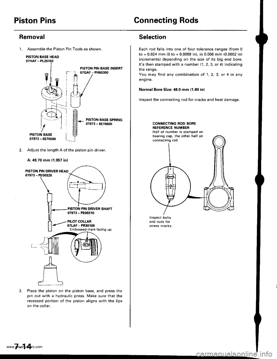
Assemble the Piston Pin Tools as shown.
PISTON BASE HEAO07HAF -PL20102
PISTON BASE07973 - 6570500
Adjust the length A of the piston pin dflver.
A: 49.70 mm 11.957 in)
PIN DRIVER HEAIPE00320
\
RIr1
nT---
u
ffi-"""-
u_ll
3. Place the piston on the piston base, and press the
pin out with a hydraulic press. Make sure that the
recessed portion of the piston aligns with the lips
on the collar.
7-14
Removal
1.
PISTON07973 -
PISTON PIN BASE INSERT07GAF - PH60300
PISTON PIN DRIVER SHAFT07973 - PEt 0310
PILOT COLLAR07LAF - PR30100Embossod mark facing up.
Selection
Each rod falls into one of four tolerance ranges (from 0
to + 0.024 mm {0 to + 0.0009 in). in 0.006 mm (0.0002 in)
increments) depending on the size of its big end bore.
lt's then stamped with a number 1.1.2,3, or 4) indicating
the range.
You may find any combination ot 1,2,3, or 4 in any
engrne.
Normal Bore Size: ,18.0 mm (1.89 in)
Inspect the connecting rod for cracks and heat damage.
CONNECTING ROD BOREREFENENCE NUMBERHalf of number is stamped onbearing cap, the other half onconnectno roo.
www.emanualpro.com
Page 183 of 1395
Intake Manifold
Replacement
NOTE:
. Use new O-rings and gaskets when reassembling.
. Check for folds or scratches on the surface of the gasket.
. Replace with a new gasket if damaged.
'97 - 98 models:
INTAK€ MANIFOLDReplace if cracked orif mating surfaces areoamageo,
INTAKE AIRTEMPERATURE
{IATI SENSOR22 N.n 12.2 kgl.m,16 rbf.ftl
8 x 1.25 mm22 N.m 12.2 kgtm.'t6 tbf ft)
8 x 1.25 mm22 N.m |.2.2 kgl.rn,'16 tbt ftl
I x 1.25 mm24 N m 12.4 kgf m.17 tbf.ft)
INTAKBRAC}
INTAKE MANIFOLOBRACKET B ('98 modell8 x 1.25 mm23 N m (2.3 kgt m,17 tbf.ftlI x 1.25 mm24 N.m 12.4 kgf.m,17 tbf.ft)
8 x 1.25 mm24 N.m (2.4 kgf.m,17 tbf.ft)
9-2
www.emanualpro.com
Page 184 of 1395
'99 - O0 modol3:
6x1.0mm9.8 N.m 11.0 kg{.m,7.2 tbtltl
NESONATOR
6x1.0mm9.8 N.m {1.0 kgf.m,7.2 rbr.ftt
O-RINGReplace.Apply oil to O-RINGbetore installing.
RESONATORCHAMBERBRACKET
GASKETReplace.
IAT SENSOR2:2N.m l2.2kgl.n,16 tbtftl
O.RINGReplace.
l
O.RINGReplace.
8 x 1.25 mm24 N.m 12.4 kgt m,17 tbt frl
INTAKE MANIFOLDReplace it cracked orif mating surfaces areoamageo.
8 x 1.25 mm22 N.m 12.2 kgl.m,16 rbf.ftt
IAC VALVE
8 x 1.25 mm23 N.m (2.3 kgf.m,17 tbf.ft,
INTAKE MANIFOLD
22 N.m 12,2 kgl.m,16 rbfftl
("\"- K\*}Gt
W\qu u
N,1\J 'n\
.a,,-\\J "
G)s
BRACKET
9-3
www.emanualpro.com
Page 185 of 1395
Exhaust Manifold
Replacement
NOTE:
. Use new gaskets and self-locking nuts when reassembling.
. Check for folds or scratches on the surface of the gasket.
. Replace with a new gasket if damaged.
'97 - 98 U.S. models (Calilornia):
8 x 1.25 mm31 N.m (3.2 kgf.m, 23 lbtft)Replace.
I x 1.25 mm24 N.m (2.4 kgl.m,1? tbf.ft)
8 x 1.25 mm24 N.m (2.i1kgt.m,
17 lbf.ftl
EXHAUSTMANIFOLO
10 x 1.25 mm44 N.m 14.5 kgf.m, 33 lbf.ft)
SELF.LOCKING NUT8 x 1.25 mm31 N m 13.2 kgt.m, 23 lbt'ft)Replace.
EXHAUST MANIFOLDBRACKET
10 x 1.25 mm44Nm{4.5kg{.m.33 lbf.ftl
NN
9-4
www.emanualpro.com
Page 186 of 1395
'97 - 98 U.S. models {Except California):'99 - 00 models:
8 x '1.25 mm31 N.m {3.2 kgl.m,23 lbl.ft)Beplace.
8 x 1.25 mm31 N.m {3.2 kgf.m.23 lbf.ft)Replace.
MANIFOLD
6x1.0mm9.8 N m 11.0 kgf.m, 7.2 lbf.ft)
COVER
(v/\
NL-]\ r-------.\\' 'r
\F=
\\/ ,l
BRACKET
44 N.m {4.5 kgf.m, 33 lbtftl
9-5
www.emanualpro.com