Page 1206 of 1395

Ground Distribution
Ground-to-Component(sl Index
GroundWire Color
G2
G3
G 10'l
G201
G202
G351
BLIVRED
BRN
BLK
BLK
BRN/BLK
BLK
BLK
BLK
23-46
Component or Circuits Grounded
Battery
Valve Cover
Transmission housing
A,/T gear position switch
ECM (PG1, PG2) ('98 - 00 models: M/T)
PCM (PG1, PG2l (Avrr)
PGM-FI main relay
Power steering pressure (PSP) switch
Radiator fan switch
VSS
Data link connector
ECM (1G1, LG2) ('98 - 00 models: M/T)
PCM (LGI, LG2) (IVT)
Shielding:
between ECM ('98 - 00 models: M/T) or PCM (Ay'T) and CKF sensorbetween ECM {'98 - 00 modets: M/T} or pCM (Ay'T) and CKp sensorbetween ECM ('98 - 00 models: M/T) or PCM (rVT) and CYP sensorbetween ECM ('98 - 00 models: M/T) or PCM (Ay'T) and TDC sensorbetween ECM {'98 - 00 models: M/T) or PCM (ly'T) and countershaft speed sensor (Ay'T)
between ECM ('98 - 00 models: M/T) or PCM {A,,/T) and mainshaft sp€ed sensor {!VT)between ECM ('98 - 00 models: M/T) or PCM (A,/T) and primary HO2Sbetween ECM ('98 - 00 models: M/T) or PCM (Ay'T) and secondary HO2SHorn (High)
Horn {Low}
Radiator fan motor
Right headlight
Right front parking light
Right front side marker light
Right front turn signal light
Condenser fan motor
Cruise actuator
Left front parking light
Left front side marker light
Left front turn signal light
Left headlight
Rear window washer motor
Windshield washer motor
ABS pump motor
www.emanualpro.com
Page 1207 of 1395

BLKG401
GroundWir€ ColorComponent or Circuits Grounded
ABS indicator circuit
ABS control unit
Ashtray light
A/T gear position indicator dimming circuit
Brake fluid level switch
Clock ('98 - 00 models)
Clutch inrerlock switch (M/T)
Clutch switch (Mff)
Cruise main switch
Cruise indicator circuit
Cruise control unit
Dash lights brightness controller
Data iink connector
Daytime running rights control unit (Canada)
Front accessary socket
Gauge and indicators
Heater control panel
lgnition key light control unit ('97 model)
lgnition key switch
Integrated control unit
Interlock control unit (Ay'T)
Parking pin switch {A,/T)
Power window relay
Rear accessary socket relay
Bear window defogger relay
Rear window wiper control unit ('97 model)
Service check connector
Spotlights
SRS indicator circuit
Turn signal/hazard relay
Windshield wiper motor
Windshield wiper/washer switch- plus everything grounded through G402
ABS control unit
Blower motor relay
Blower motor high relay
ELD unit (USA)
Power transistor- plus everything grounded through G401
BLKG402
{cont'd)
23-47
www.emanualpro.com
Page 1218 of 1395
Gauge Assembly
Circuit Diagram
BATTERY
@*"
UNOER.IIOOD FUSE/RELAY 8OX
No.41 (100A) No.42 (40A)
UNOER_DASHFUSEiNELAY BOX
|
'''
IRED
-I
DASH LIGHTSBRIGHTNESSCONTROLLER
l-8LK
G401G4A2
CRUISECONTROLUNIT
23-58
JALTERNATOR
| 0l
IBLU/RED
-I
ABSCONTROLUNIT
JSRS UNIT
YEL
E5 GAUGE ASSEMSLY
www.emanualpro.com
Page 1244 of 1395
Brake Lights
High Mount Brake Light
Replacement
1. Push the clips, and remove the cover from thehousing.
Disconnect the connectors.
Remove the two nuts and the housing.
2.
HOUSING
Gircuit Diagram
UNDER.HOODFUSE/RELAY BOXBATTENY
/,i | No.s2 {15A) |
\Y*-I=f*-'o*T*'no"l
IV
T:,^-,
HORNSYSTEM
I
i.t53l| *",*"",
GRNA,VHT
GBNMHT -.1
I
I
. ABS CONTFOLUNIT' ECM/PCM. CRUISE CONTROLUNIT
GRNAVHT GRNWH
ll
tl
A[$^Jlr A
Yi,?'il Y
tlBLK BLK
llrl
IBLK
I
I
d
oi,,
RIGHTEFAKELIGHT(21w)
LEFIBFAKELIGHT(2rw)
BLK
G553
23-84
www.emanualpro.com
Page 1312 of 1395
Component/Wiring Locations Index -'97 model
SRS INDICATOR LIGHT (ln the gauge assembly)Troubleshooting, page 24-27Gauge assembly, section 23
DASHBOABD w|RE HARNESS
to SBS INDICATOR LIGHT in
DRIVER'S AIBMGReplacement,page 21-87Disposal, page 24-97
To CRUISE CONTROLSET
To DRIVERS AnBAG
ANBAG2P
sBsitAr[ ] nNEssto FROI|T PASSEiIGEB.S
FRONT PASSEITGER'S AIRBAGReplacement, pago 24{9Disposal, page 24-97
sns ut{fTGROUND
SES MAIN HAR]GSStosns U nItP OOIIITECTOR
MAIN WIRE HABNESSto DASHBOABD wlRE21P
SRS MAIN HABNESSto UNOEB-DASHFUSE/BELAY BOX2P CONNECTOR
GOf$ECrOn PPIlBLr( 8R t
MEMORY ERASE SIGNALIMES) CONNECTOR I2PI[GRY. GRYI or twHT, BLr.l
GAUGE ASSEMBLY5P
HARNESS
SRS MAIN HARNESSto MAINWIRE HARNESS3P OONNECTOR
24-15
www.emanualpro.com
Page 1313 of 1395

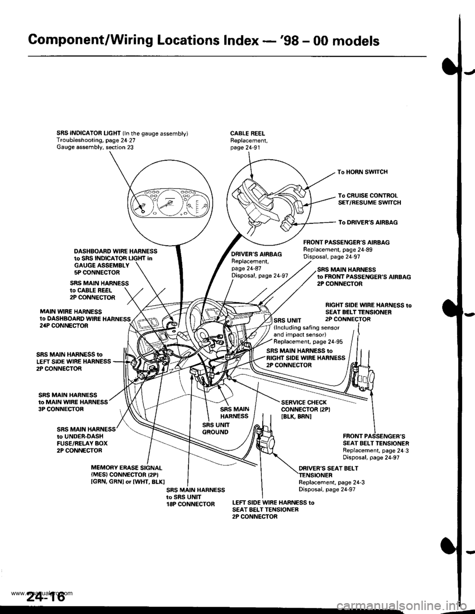
Gomponent/Wiring Locations Index -'98 - 00 models
SRS INDICAIOR LIcHT (ln the gauge assembty)Troubleshooting, page 24 27Gauge assembly. section 23
DASHBOARD WIRE HARNESSto SRS INDICATOR LIGHf inGAUGE ASSEMBLY5P CONNECTOR
FRONT PASSENGER'S AIRBAGReplacement, page 24-89Disposal, page 24 97
CABLE REELReplacement,page 24-91
To HORN SWITCH
To CRUISE CONTROLSET/RESUME SWTCH
To DRIVER'S AIRBAG
ro CABLE REEL2P CONNECTOR
MAIN VYIRE HARNESSto DASHBOARD WIRE HARNESS
SRS MAIN HARNESS
ORIVER'S AIRBAGReplacement,page 24-87Disposal, page 24-97
SRS UNIT
SRS MAIN HARNESSto FROI{T PASSENGER,S AIRBAG2P CONiIECTOR
RIGHT SIDE WIRE HARNESS toSEAI BELTTENSIONER2P CONNECTOR24P CONNECTOR
SRS MAIN
SRS MAIN HARNESS toLEFT SIDE WIRE HARNESS2P CONNECTOR
SRS MAIN HARNESSto MAIN WIRE HARNESS3P CONNECTOB
(lncluding safing sensorand impact sensor)Replacement, page 24-95
SRS MAIN HARNESS toRIGHT SIDE WIRE HARNESS2P CONNECTOR
SERVICE CHECKCONNECTOR I2PIIBLK BRNI
to UNDER-DASHFUSE/RELAY BOX2P CONNECTORSEAT BELT TENSIONERReplacement, page 24 3Disposal, page 24-97
ORIVER'S SEAT BELTMEMORY ERASE SIGNAL(MES) CONNECTOR I2PIIGRN, GRNI or IWHT, BLKIReplacement, page 24-3Disposal, page 24-97
LEFT SIDE WIRE HARNESS toSEAT BELTTENSIONER2P CONNECTOR
24-16
.4
www.emanualpro.com
Page 1316 of 1395

Precautions/Procedures
)General Precautions
Carefully inspect any SRS part before you install it.
Do not install any part that shows signs of being drop-
ped or improperly handled, such as dents, cracks or
deformation:
- Airbags- Cable reel- SRS unit- Seat belt tensioners
N
)-
Use only a digital multimeter to check the system, lf
it's not a Honda multimeter, make sure its output is
10 mA (0,01 A) or less when switched to the smallest
value in the ohmmeter range. A tester with a higher
output could damage the airbag circuit or cause acci-
dental deployment and possible injury.
Do not install used SRS Dans from another vehicle,
When making SRS repairs, use only new pans.
Except when performing electrical inspections,
always disconnect both the negative cable and posi-
tive cable from the batterv. and wait at least three
minutes before beginning work.
Replacement of the combination light and wiper/
washer switches and cruise control switch can be
done without removing the steering wheel:
- Combination light and wiper/washer switch replace-
ment {see section 231.- Cruise control sevresume switch replacement (see
section 41.
Whenever the ignition switch is ON {ll}, or has been
turned OFF for less than three minutes, be careful not
to bump the SRS unit; the airbags could accidentally
deploy and cause damage or injuries.
Whenever the airbag has been activated, replace the
SRS unit.
The original radio has a coded theft protection circuit.
Be sure to get the customer's code number before dis-
connecting the battery cables.
)
Airbag/Seat Belt Tensioner
Handling and Storage
Do not try to disassemble an airbag or a seat belt ten-
sioner. They have no serviceable parts. Once an airbag
or a seat belt tensioner have been deployed. they cannot
be repaired or reused.
For temporary storage of an airbag or a seat belt ten-
sioner during service, please observe the following pre-
cautons:
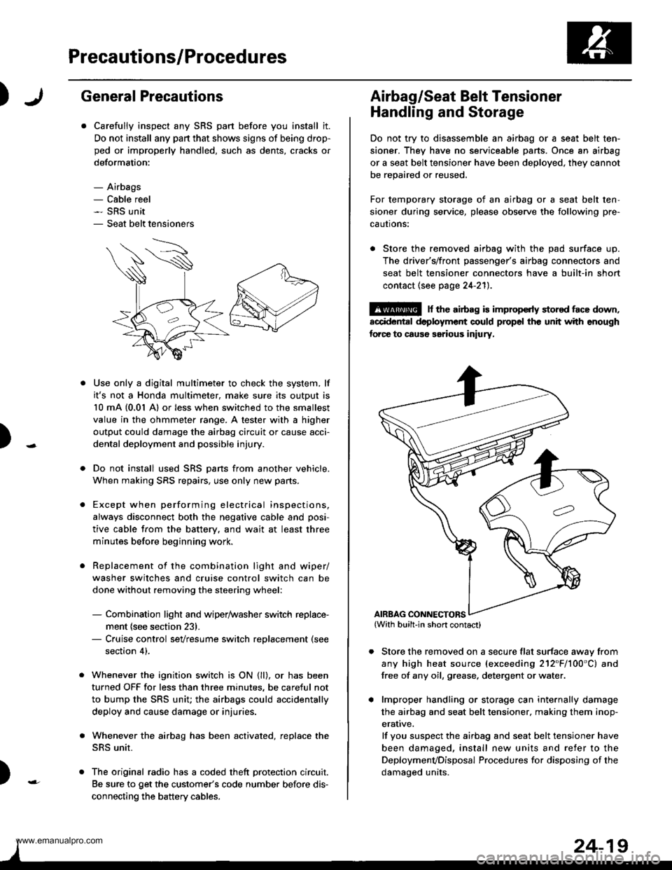
. Store the removed airbag with the pad surface up.
The driver's/front passenger's airbag connectors and
seat belt tensioner connectors have a built-in short
contact (see page 24-211.
@ r th€ airb.g is impropcrty stor€d face down,
accidental deployment could propel the unit with enough
forc€ to caus6 serious iniury,
Store the removed on a secure flat surface awav from
any high heat source (exceeding 212"F/100'C) and
free of any oil, grease. detergent or water.
lmproper handling or storage can internally damage
the airbag and seat belt tensioner. making them inop-
erative.
lf you suspect the airbag and seat belt tensioner have
been damaged, install new units and refer to the
Deploymenvoisposal Procedures for disposing of the
damaoed units.
AIRBAG CONNECTORS
www.emanualpro.com
Page 1385 of 1395
Driver's Airbag
Replacement lcont'd)
CAUTION: 8. sure to instattthe SRS wiring so that it isnot plnched or inlerfsring with other parts.
4. Place the new driver's airbag into the steeringwheel, and secure it with new Torx bolts.
TORX EOLTS9.8 N,m 11.0 kgl.m, 7.2 tbf,ftlFeplace.
24-88,
5. Connect the driver's airbsg 2p connector to thecable reel 2P connector, then install the accesspanel on the steering wheel.
Connect the battery positive cable. then connect thenegative cable.
After installing the airbag assembly, confirm proper
system operation:
. Turn the ignition switch ON llt); the SRS indica-tor light should come on for about six secondsand then go off.. Mske sure both horn buttons work.o Take a test-drive, and make sure the cruise con-trol switches work.
7.
2P CONNECTOR
www.emanualpro.com